Page is loading ...

OPERATING INSTRUCTIONS
LTFE 110/210/310/410/510

2
INDEX PAGE
Low Temperature Freezer . . .................................. . . ........................
Placing the freezer ... . ........ . . .......................... . . .........................
Electrical supply. . ......... . . ........................................................
Starting Up . ............. . . ..... . . .................................................
Temperature adjustment . . .... . . ......................................................
Before commissioning ......... . . ....................................................
Operating the freezer . . ..... . . ........................................................
Defrosting ............ . . ....... . . ...................... . . ..........................
Cleaning .......... . ..... . . ..... . . .................................................
Storage . . ...................... . . ...................... . . .........................
Control panel ......................................................................
Trouble shooting .............. . . ....................................................
Disposal ........... . . . . ... . . ......................................................
Service . . ........... . . . .... . . .....................................................
Wiring diagram ............................................. . . ...............
Standard Setting of EVCO Controller
EVK 012 Controller
.................................................
...............................................................
....
10-11
3
3
3
3
3
3
4
4
4
4
5
6
6
6
7
8 - 9
..

Low Temperature Freezer
In order to get the maximum advantage from your freezer it is important that it is placed in the correct
position. This manual should therefore be read carefully. Keep the manual in a place where it can always be
found for reference. Even with careful attention to the freezer, a mishap may occur, with the consequence
that the contents of the cabinet could be lost, therefore product insurance is recommended.
Placing the freezer
The freezer should not be placed where it might be splashed with
water, in extreme high humidity or in direct sunlight. Any of these
factors may lead to a reduction in performance and shorten the
life span of the components. The freezer should be placed on a
horizontal level, and should not be placed close to a heating
appliance or heating tubes.
Allow a minimum of 50mm (2”) clearance on the side and the
back. The side with the ventilation grill should have a clearance
of at least 100 mm (4”) in order to allow the heat from the
compressor motor to dissipate.
Electrical supply
The electrical supply should always be in accordance with the rating plate on the back of the freezer.
The supply must always be in accordance with the law and regulations regarding electrical safety, if any
doubts contact your supplier.
Starting Up
In case the compressor does not start when the freezer has been plugged in, the electrical supply may not
be in order. Check if there is an electricity supply to the plug or if the fuse is blown.
Temperature adjustment
The thermostat controls the temperature inside the cabinet. The control is placed in the compressor
compartment. The higher the number on the dial the lower the temperature. A to low temperature inside the
cabinet will increase the power consumption. Please check that the temperature is not too low, it must be at
an adequate level. When the freezer is loaded with products, please make sure that they have a
temperature of at least -20°C.
As the appliance is not suitable for freezing products, but meant as a storage unit for pre frozen products. If
products warmer than -15°C are placed in the freezer, there are a risk of damaging products already in the
freezer. The products should never be placed above the load line marking inside the cabinet.
Before commissioning
Before commissioning the interior of the freezer should be cleaned with tepid water and dried of with a clean
cloth. Never use soda or an abrasive cleaning agent as they may damage the inner liner.
3

4
Operating the freezer
The empty freezer should be switched on for at least 5-6 hours prior to loading of the freezer.
The freezer should not be loaded above the inside aluminium walls which is also the load line limit.Please
note: After the lid has been opened, there will be a vacuum created inside the freezer due to the low
temperatures. Wait a few minutes before trying to re-open the lid otherwise the handle could be damaged.
Defrosting
In order for the freezer to work to its maximum efficiency the
cabinet should be defrosted when a approx. 2mm thick ice
layer has formed inside the cabinet.
The ice layer is easily removed with a plastic or wooden
scraper. Never use a sharp metal object which might will
cause damage to the inner liner.
The defrosting frequency is determined mainly by
two factors the usage pattern (number of lid openings) and
the relative humidity.
Excess water can be drained out by using the drain water
outlet on the front of the freezer.
Cleaning
Cleaning should be done when needed. When used in a dirty
environment it might be necessary to remove the compressor
compartment and clean the compressor compartment
eventually with a vacuum cleaner.
If the cleaning process is neglected there is a risk that the
performance of the freezer will be affected, and even damage
to the compressor could occur due to overheating.
Storage
If the freezer is stored for a period of time, the lid should be kept open for free circulation of air inside the
cabinet in order to avoid corrosion of the inner liner.

Control panel
The temperature inside the freezer is controlled by the electronic controller placed in the front grill.
The controller has a digital readout of the temperature inside
the cabinet and the option of changing the wanted
temperature. Factory setting is -45°C (-49°F).
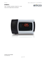
EVCO Controller
Functions
How to see the set point
1. Press and immediately release the SET key, the display will now show the set point value.
2. Press and immediately release the SET key or wait for 60 seconds to display the probe value again.
How to lock and unlock the keyboard
1. Press the up and down keys simultaneously for more than 2 seconds.
How to change the set point
1. Press the SET key to change the set point value.
2. The set point value will be displayed and the OUT1 icon starts flashing.
3. To change the set point value, push the up or down arrow.
4. To memorise the new setting press the SET key again or wait 60 seconds for the controller to return to
normal display of the probe temperature.
Setting the controllers offset value
The freezer is designed for long time and safe storage of sensitive items.
Depending on the actual situation it might be necessary to change the controllers offset value in order to get
a correspondence between the reading on the display and the actual temperature inside the cabinet.
The factory setting is an offset of 2°C.
The offset can be adjusted by doing the following
Unlock the keyboard.
Enter the programming mode by pressing the up and down arrow keys for 4 seconds.
Select the parameter “PA” by pressing the SET key to display its value.
Use arrow up or down to change its value to -19 and press SET button again.
Once display shows again PA, keep pressed up and arrow down keys for 4 seconds.
Now you are looking parameter list, select CA1 (offset).
The offset can be adjusted to +/-25°C.
5
Press set to store the new value.
Press up + down arrow for 4 seconds or wait 60 seconds without pressing any key. The new value will now
be stored.

Trouble shooting
If the freezer has stopped working, please check the following before calling for service.
Has the freezer been switched of at the mains?
Is the fuse blown?
Is the plug properly in place?
Is the thermostat set correctly?
The freezer is running continuously.
Thermostat is set to a to low temperature, lowest temperature is -45°C at 30°C ambient temperature.
Is the temperature around the freezer higher than 30°C?
Is there a heavy formation of ice inside the freezer?
Has the freezer recently been filled with larger amounts of warm items?
Is the compressor compartment clean? The cupper coil inside the compressor compartment should be free
from dust and grease.
Note:
Before removing the grill to the compressor compartment the freezer should be disconnected from the
mains.
After having checked the above mentioned points and the freezer is still not working satisfactorily, please
contact your dealer.
Disposal
When a freezer is discarded, it must be disposed in accordance with local legislation.
Service
Before calling a service engineer please read the paragraph “Trouble shooting”.
After having checked these points and the unit is still malfunctioning, please contact your supplier.
6

7
If you have checked the above points and the appliance is still not working as
expected, please contact your local dealer for further advice.
For more detailed information about programming the EVCO controllers please
consult the attached manuals.
Standard Setting of EVCO Controller
gnitteS lebaL noitpircseD
C°54- PS STNIOP TES
3 0r )siseretsyH( laitnereffiD
0 1AC tesffO
C°01 1A mralA .pmeT woL
C°01 5A mralA .pmeT hgiH
-
+

User Instructions Low Temperature Freezers Model UNI/LT 6
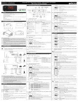
EVK 012
Thermoregulator for general purposes
18 Wiring diagram
With reference to the wiring diagrams:
• the polarity of relay K1 depends on parameter
u9; according to the default setting, the relay
is activated when the regulator is turned off
and deactivated when the regulator is turned
on
• the polarity of relay K2 depends on parameter
u3; according to the default setting, the relay
is activated during the normal operation and
deactivated during an alarm
• the serial port (by request) is the port for the
communication with the supervision system
(through a serial interface, via TTL, with MOD-
BUS communication protocol) or with the
programming key; the port must not be used
at the same time for the same purposes.
Additional information for electrical connec-
tion:
• do not operate on the terminal blocks with
electrical or pneumatic screwers
• if the instrument has been moved from a cold
location to a warm one, the humidity could
condense on the inside; wait about an hour
before supplying it
• test the working power supply voltage,
working electrical frequency and working
electrical power of the instrument; they must
correspond with the local power supply
• disconnect the local power supply before
servicing the instrument
• do not use the instrument as safety device
• for repairs and information on the instrument
please contact Evco sales network.
19 USER INTERFACE
19.1 Turning on/off the instrument
To turn on the instrument you have to supply
it; to turn it off it is enough to cut off the power
supply.
19.2 Locking/unlocking the keyboard
To lock the keyboard:
• make sure no procedure is running
• press and 2 s: the display will show
“Loc” 1 s.
If the keyboard is locked, you will not be al-
lowed to:
• modify the working setpoint with the proce-
dure related in paragraph 4.1 (you also can
modify the working setpoint through param-
eter SP).
These operations provoke the visualization of
the label “Loc” 1 s.
To unlock the keyboard:
• press and 2 s: the display will show
“UnL” 1 s.
19.3 Silencing the buzzer
• make sure no procedure is running
• press a button (the first pressure of the button
does not provoke its usual effect).
20 SETTINGS
20.1 Setting the working setpoint
• make sure the keyboard is not locked and no
procedure is running
• press LED out 1 will flash
• press or in 15 s; also look at param-
eters r1, r2 and r3
• press or do not operate 15 s.
You also can modify the working setpoint
through parameter SP.
20.2 Setting configuration parameters
To gain access the procedure:
• make sure no procedure is running
• press and 4 s: the display will show
“PA”
• press
• press to set “-19”
• press
• press and 4 s: the display will show
“SP”.
To select a parameter:
• press or
To modify a parameter:
• press
• press or
• press or do not operate 15 s.
8

User Instructions Low Temperature Freezers Model UNI/LT
To quit the procedure:
• press and 4 s or do not operate
60 s.
Switch off/on the power supply of the instru-
ment after the modification of the param-
eters.
21 SIGNALS
LED MEANING
out 1 LED load
if it is lit, the load will be turned on;
also look at parameter u9
if it flashes:
• the modification of the working
setpoint will be running
• a load protection will be running
(parameters C1 and C2)
LED defrost
if it is lit, the defrost will be running
LED alarm
if it is lit, an alarm will be running
°C LED Celsius degree
if it is lit, the unit of measure of the
temperatures will be Celsius degree
(parameter P2)
°F LED Fahrenheit degree
if it is lit, the unit of measure of the
temperatures will be Fahrenheit de-
gree (parameter P2)
CODE MEANING
Loc the keyboard and/or the working
setpoint are locked (parameter r3);
also look at paragraph 2.5
22 ALARMS
CODE MEANING
ALARM First temperature alarm
LOW Remedies:
AL1 • check the room temperature
• look at parameters A1 and A3
Effects:
• the alarm output will be deacti-
vated; also look at parameter u3
ALARM Second temperature alarm
HIGH Remedies:
AL2 • check the room temperature
• look at parameters A5 and A7
Effects:
• the alarm output will be deacti-
vated; also look at parameter u3
When the cause that has provoked
the alarm disappears, the instrument
restores the normal operation.
23 INTERNAL DIAGNOSTICS
CODE MEANING
Pr1 Room probe error
Remedies:
• check the integrity of the probe
• check the connection instrument-
probe
• check the room temperature
Effects:
• the load activity will depend on
parameters C4 and C5
• the alarm output will be deacti-
vated; also look at parameter u3
When the cause that has provoked the alarm
disappears, the instrument restores the normal
operation.
79

Wiring diagram for LTFE 110 / 210 / 310
Power supply
Alarm

Wiring diagram for LTFE 410 / 510
Power supply
Alarm

50 80 003-0-GB
WWW.ARCTIKO.COM
LAMMEFJORDSVEJ 5
DK-6715 ESBJERG N
DENMARK
TEL. +45 70 20 03 28
FAX +45 70 20 03 29
WWW.ARCTIKO.COM
/


