Page is loading ...

Manual
Outdoor Stand-Alone
Weatherproof Keypads
Model
Number
2 Relay
Outputs
Backlit
Keys
Proximity
Reader
Mullion-Style Keypads
SK
-
2323
-
SDQ
SK
-
2323
-
SPQ
Sealed-Environment Keypads
SK
-
1
323
-
SD
Q
SK
-
1323
-
SP
Q
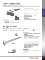
(SK-2323-SDQ shown) (SK-1323-SPQ shown)

ENFORCER Outdoor Stand-Alone Keypads
2 SECO-LARM U.S.A., Inc.
Features
:
Table of Contents:
Specifications:
12~24 VAC/VDC operation
1,010 User codes
2 Form C relays, each rated 1A@30VDC
Each relay has programmable output time
from 1~99 seconds or toggle
Output #2 can be programmed for use
with a doorbell
2 Egress inputs for exiting the premises without
keying in the code
Backlit keys for easy nighttime use
Able to mount to a single-gang back box
Operating voltage
12~24 VAC/VDC
Current draw
Stand
by
64
mA@12VDC
1 Relay active
92mA@12VDC
2 Relays active
120mA@12VDC
Relay outputs
Output #1
1
A@
30
VDC, Form C, NO/
NC/COM
Output #2
1A@30VDC, Form C, NO/NC/COM
Egress inputs
Input #1
N.O. Ground
Input #2
N.O. Ground
Door sensor input
N.C. Ground
Tamper sensor
Optical
Operating temperature
-
4°~122° F (
-
20°~50° C)
Keypad LED life
60,000 hours (over 6.8 years)
Weight
SK
-
1323 Series
1
-
lb 2
-
oz (
510
g
)
SK
-
2323 Series
11
-
oz
(312g)
Proximity reader frequency
(SK-2323-SPQ and SK-1323-SPQ only) 125kHz
Proximity reader distance
(SK-2323-SPQ and SK-1323-SPQ only) 2" (5cm)
Sample Wiring and Applications ............... 6-7
User Control Chart ..................................... 8-9
Programming Instructions ...................... 10-13
Resetting the Keypad .................................. 14
Manually Resetting the Master Code .......... 14
Factory Defaults .......................................... 14
Using the Keypad ........................................ 15
Troubleshooting .......................................... 15
Quick Reference Guide ............................... 16
Warranty ..................................................... 16
Features ........................................................ 2
Specifications ................................................ 2
Also Available from SECO-LARM ................. 2
Dimensions .................................................... 3
Parts List ....................................................... 3
LED & Audible Indicators .............................. 3
Optical Tamper .............................................. 3
Important Notes ............................................. 4
Wiring Diagram .............................................. 4
Installation ..................................................... 5
Door sensor input for anti
-
tailgating operation
All features are programmed directly from the
keypad - no need for an external programmer
EEPROM memory protects programmed
information in case of power loss
Optical tamper for added security
Circuitry is potted with epoxy for outdoor use
IP65 weatherproof rating, rugged aluminum
construction
Built-in proximity card reader
(SK-2323-SPQ and SK-1323-SPQ only)
Also Available from SECO-LARM:
PR-K1S1-A: Proximity cards.
(Sold in packs of 10)
PR-K1K1-AQ: Proximity key fobs.
(Sold in packs of 10)

ENFORCER Outdoor Stand-Alone Keypads
SECO-LARM U.S.A., Inc 3
LED & Audible Indicators:
Optical Tamper:
Audible
T
ones
Keypad Status
1 Long tone
Confirmation
1 Short tone
Key press
2 Short tones
Invalid entry
3 Short tones
User code/card denied
Constant short tones
Alarm triggered
6 short + 1 long tone
All user codes deleted
No tone when key is pressed
Wrong code lockout
Left LED
Right LED
Keypad Status
OFF
Green
Power ON
OFF
Red
Programming Mode
Green
Red
flashing
Waiting to program code/card* (card+code access mode)
Red
Red
flashing
Code/card* already present
Green
Green
Relay 1
activated
Red
Green
Relay 2 activated
Red
Green
Relay 1 and 2 both activated
Red
Red
Restoring factory defaults
Green flashing
Green
Waiting for code/card entry* (card+code access mode)
OFF
OFF
Power OFF / Clearing user codes
There is an optical tamper on the rear of each unit. If the sensor detects light, the tamper alarm will sound.
For information on how to program the optical tamper, please see pg. 13, Programming the Optical Tamper.
SK-2323 Series SK-1323 Series
Rear Rear
Optical
tamper
Parts List:
1x Keypad
1x Manual
4x Mounting screws
4x Screw anchors
1x Metal oxide
varistor (MOV)
1x Security screw
1x Torx wrench
*Card operation with SK-2323-SPQ
and SK-1323-SPQ only.
1x Mounting template
1x Diode
Dimensions: SK-2323 Series
SK
-
1
323
Series
6"
(
152
mm)
15/16" (24mm) 13/4" (44mm)
35/16"
(
84
mm)
39/16"
(
90
mm)
35/16"
(
84
mm)
39/16"
(
90
mm)
2" (50mm)
3" (76mm)
43/4"
(120mm)
7
/
8
" (22mm)
13/16" (30mm)

ENFORCER Outdoor Stand-Alone Keypads
4 SECO-LARM U.S.A., Inc.
Important Notes:
IF USING THE KEYPAD WITH A MECHANICALLY OPERATED DOOR OR
GATE, MOUNT THE KEYPAD AT LEAST 5’ (15m) FROM THE DOOR OR
GATE TO PREVENT USERS FROM BEING CRUSHED OR PINNED.
FAILURE TO DO SO MAY RESULT IN SERIOUS INJURY OR DEATH
.
! !
1.
Always disconnect power before s
ervicing the keypad.
2. The keypad must be properly grounded. Use a minimum 22AWG wire connected to the Uninsulated
Chassis Ground wire. Failure to do so may damage the keypad.
3. All wiring and programming should be done by a professional installer to reduce the risk of
improper installation.
4. Basic keypad functions are located on pg. 16
of this manual. Be sure to store this manual in a safe place for
future reference.
5. If using VAC, use the Green Common Ground wire for all sensor input.
Wiring Diagram:
*Chassis
Ground:
Connect a
continuous wire
from the
Uninsulated Chassis
G
round
w
ire to a grounding
point to avoid damage from static discharge. A good grounding point could include a grounded metal
conduit, a cold water pipe, or a grounding rod. Use 18AWG wire for earth ground for best results. Wire
used must be at least 22AWG.
SK-2323 series shown. Wiring is the same for both series.
Black
Red
Brown
Orange
Yellow
Green
Pink
Aqua
Ground (-)
Power (+)
Door Sensing Input (N.C.)
Egress Input #1 (N.O.) Triggers Output #1
Egress Input #2 (N.O.) Triggers Output #2
Common Ground (-)
Output #1 (N.O.)
Blue
Purple
Gray
Output #1 (COM)
Output #1 (N.C.)
Output #2 (N.O.)
Output #2 (COM)
Output #2 (N.C.)
12~24 VAC/VDC
Uninsulated Chassis Ground*

ENFORCER Outdoor Stand-Alone Keypads
SECO-LARM U.S.A., Inc 5
Installation:
1.
Find a
suitable location to mount the keypad. Do not install where it will be too high or too low for most
users to operate the keypad.
2. Using the included Torx wrench, unscrew the security screw located on the bottom of the keypad’s
mounting bracket.
3. Carefully remove the keypad from the mounting bracket.
4. Drill holes in the 4 designated mounting points located on the mounting bracket. If needed, use the
included mounting template.
5. Using the 4 included mounting screws, secure the mounting bracket to a wall or other mounting surface.
If mounting to brick or drywall, it may be necessary to use the included screw anchors.
6. If the installation is using surface wiring, mount the keypad to a single-gang box using the 2 single-gang
box mounting points.
7. Connect each of the wires that will be used to operate the keypad according to the wiring diagram
on pg. 4.
8. Reattach the keypad to the mounting base.
9. Use the included Torx wrench to tighten the security screw and secure the keypad to the base.
SK-1323 Series
SK-2323 Series
Keypad
Keypad
Mounting
bracket
Mounting
bracket
Mounting
screws
Mounting
screws
Security screw
Security screw
Mounting
screws
Mounting
screws
Single-gang box
mounting point
Single-gang box
mounting point
Single-gang box
mounting point
Single-gang box
mounting point

ENFORCER Outdoor Stand-Alone Keypads
6 SECO-LARM U.S.A., Inc.
1 Connect included diode and metal oxide varistor (MOV) as close as possible and in parallel with an electric
strike. This absorbs possible electromagnetic interference to prevent operation of the strike from damaging
the keypad. Do not connect a diode or MOV when using electromagnetic locks.
2 Output #2 controls the arm/disarm of the alarm control panel. Consult the alarm control panel manual for
more information.
Connecting to a Doorbell:
If the keypad is connected to a doorbell, press to activate the doorbell. T
he doorbell output lasts for 1
second. For instructions on how to program the keypad for doorbell, see pg. 13, Programming the Output
#2 Function.
Purple—Output #2
Blue—Output #2
12~24
VAC/VDC
Power
Supply
Doorbell
Sample Wiring and Applications:
(SK
-
1323 series shown.
All examples apply to both the SK
-
1323 and SK
-
2323 series.)
NOTE
: Sample applications are based on VDC power supplies.
Connection to Lock Device and Alarm System Arm/Disarm Control:
Orange—Egress Input 1 (N.O.)
Uninsulated Chassis Ground
Black—12~24 VAC/VDC (-)
Red—12~24 VAC/VDC (+)
Pink—Output #1 (COM)
Yellow—Egress Input 2 (N.O.)
—Output #1 (N.O.)
Aqua—Output #1 (N.C.)
Blue—Output #2 (N.O.)
Purple—Output #2 (COM)
Gray—Output #2 (N.C.)
To Chassis Ground
Electric Strike
N.O.
N.C.
12~24
VAC/VDC
Power Supply
Alarm
Control
Panel2
Egress
Button Egress
Button
Diode1
MOV1
Green—Common ground (-)

ENFORCER Outdoor Stand-Alone Keypads
SECO-LARM U.S.A., Inc 7
The door sensing input is used for anti
-
tailgating. When used with a N.C. magnetic contact the relay will
de-energize one second after the door has been closed. This will bypass any existing relay timing.
*
Connect included diode and metal oxide varistor (MOV) as close as possible and in
parallel with an electric
strike. This absorbs possible electromagnetic interference to prevent operation of the strike from damaging
the keypad. Do not connect diode or MOV when using electromagnetic locks.
Door Sensing:
Brown—Door Sensing
Green—Common ground (-)
N.C. Dry Contact
Shunting an Alarm N.C. Zone:
Purple—Output #2 (COM)
Blue—Output #2 (N.O.)
N.C. Dry Contact
Alarm
Control
Panel
Door-Hold-Open Code:
Output #1 and Output #2 can be wired
together in such a way that electric lock devices remain unlocked as
long as Output #2 is activated.
For N.O. Locking Devices
Purple—Output #2 (COM)
Pink—Output #1 (COM)
Blue—Output #2 (N.O.)
—Output #1 (N.O.)
Electric Strike
Diode
MOV
12~24
VAC/VDC
Power
Supply
For N.C. Locking Devices
Aqua—Output #1 (N.C.)
Pink—Output #1(COM)
Gray—Output #2 (N.C.)
Purple—Output #2 (COM)
Electric Strike
Diode
MOV
12~24
VAC/VDC
Power
Supply

ENFORCER Outdoor Stand-Alone Keypads
8 SECO-LARM U.S.A., Inc.

ENFORCER Outdoor Stand-Alone Keypads
SECO-LARM U.S.A., Inc 9

ENFORCER Outdoor Stand-Alone Keypads
10 SECO-LARM U.S.A., Inc.
4. Exit Programming Mode by pressing
.
Program a new Master Code immediately.
Take note of the keypad status LEDs—
o Right LED Solid Green: Standby Mode
o Right LED Solid Red: Programming Mode
o Left LED Solid Green / Right LED Flashing Red: Awaiting code/card entry
If you are unsure of which mode the keypad is in, press
until the right LED is green. The keypad is now
in the Standby Mode. Enter the master code twice to return to Programming Mode.
Enter:
1.
Codes are programmed to
be
2~6 digits in length. All codes must be the same length.
2. Before inputting any of the following, enter Programming Mode by entering the
Master Code twice. The default Master Code is 1234.
To enter Programming Mode, enter
3. To exit Programming Mode, press the key.
4. The keypad will exit Programming Mode if no keys are pressed for 30 seconds.
Programming Instructions:
#
Programming Tips
:
#
First Time Keypad Use
:
Take these steps the first time the keypad is programmed.
1. Enter Programming Mode by entering the Master Code twice.
(Default Master Code is
1234
)
.
2. Enter
.
.
3. Enter the new Master Code
twice
.
The Master Code may
not
be the same as a user code.
C.
Program the Master Code
3
Example:
If the desired new Master Code is
4321
, enter:
4
3
2
1
4
3
2
1
4. Exit Programming Mode by pressing
.
A.
Enter Programming Mode
(Default Master Code is
1234
).
*SK
-
2323
-
SPQ and SK
-
1323
-
SPQ only.
B.
Program Code Length
1. Enter Programming Mode by entering the Master Code twice.
(Default Master Code is
1234
)
.
2. Enter .
.
9
3. Enter the
desired code length
.
This must be a number from 2~6.
WARNING:
After a new code length is programmed, all user codes will be d
eleted and the
master code
will be reset.
1
2
3
4
1
2
3
4
1
2
3
4
1
2
3
4
NOTE
:
The Master Code will reset depending on the programmed code length. These will be the new
Master Codes after the code length is reset:
Code Length
New Master Code
2
digits
12
3
digits
123
4
digits
1234
Code Length
New Master Code
5
digits
12345
6
digits
123456
0
4
NOTE
:
To keep the default 4
-
digit code length, skip to step C,
Program the Mast
er Code
.

ENFORCER Outdoor Stand-Alone Keypads
SECO-LARM U.S.A., Inc 11
6
. Exit Programming Mode by pressing again.
4.
Exit Programming Mode by pressing
.
Programming Output #1
:
2. Enter
.
E.
Setting the Output #1 Access Mode*
DEFAULT: User card
OR
user code.
0
1. Enter Programming Mode by entering the Master Code twice.
0
0
User card
ONLY
Either user card
OR
user code
(DEFAULT)
0
1
3. Enter one of the following:
0
2
User card
AND
user code
1
. Enter a user ID number.
Each Output #1 user can be programmed to have a
user code, a user card, or both user code and card.*
A.
Programming User Codes
4
. To program the next user, repeat from step
1
in section
A
,
B
, or
C
.
5
. Exit Programming Mode by pressing
.
2
. If the left LED is red, previous user data exists. Clear it by entering
.
The keypad will beep in
confirmation and the left LED will turn green.
3
. Enter a new user code.
(
to
)
0
0
0
9
9
9
NOTE
:
For all of the following programming functions, the keypad must be in Programming Mode. To enter
Programming Mode, enter the Master Code twice.
NOTE:
Deleting all users is recommended before changing the acc
ess mode to user card with user
code. See pg. 14, Deleting All Users.
*SK
-
2323
-
SPQ and SK
-
1323
-
SPQ only.
D.
Program the Master Card
(SK
-
1323
-
SPQ and SK
-
2323
-
SPQ only)
In addition to a Master Code, a Master Card can also be programmed. Swiping a Master Card will give
direct access to Programming Mode.
1.
Enter Programming Mode by entering the Master Code twice. (Default Master Code is
1234
)
2.
On the keypad, enter
.
7
4.
Swipe a proximity card (PR
-
K1S1A or similar). This card is now the Master Card.
5.
Exit Programming Mode by pressing .
3.
If the left LED is solid green and the right LED is flashing
red
, a Master card is already
programmed. Clear it by entering . The keypad will beep in confirmation and the left LED
will start flashing green.
1
. Enter a user ID number.
4
. Return to Programming Mode by pressing
.
3
. Swipe a new
user card.
5
. To program the next user, repeat from step
1
in section
A
,
B
, or
C
.
B.
Programming User Cards
*
2
. If the left LED is red, previous user data exists. Clea
r it by entering . The keypad will beep in
confirmation and the left LED will turn green.
(
to
)
0
0
0
9
9
9

ENFORCER Outdoor Stand-Alone Keypads
12 SECO-LARM U.S.A., Inc.
Deleti
ng or Changing the Master Card*
Programming Output #2
:
Each Output #2 user may only have a user code
OR
a user card programmed.
*SK
-
2323
-
SPQ and SK
-
1323
-
SPQ only.
NOTE
:
For all of the following programming functions, the keypad must be in Programming Mode. To enter
Programming Mode, enter the Master Code twice.
Continued from pg. 11.
B.
Programming an Output #2 User Card*
A.
Programming an
Output #2 User Code
5
. To program t
he next user, repeat from step 2
in section
A
or
B
.
7
. Exit Programming Mode by pressing
again.
4
. Swipe a new user card.
2
. Enter a user ID number.
6
. Return to Programming Mode by pressing
.
1
. Enter
.
4
3
. If the left LED is red, previous user data exists. Clea
r it by entering . The keypad will beep in
confirmation and the left LED will turn green.
(
to
)
0
0
0
9
Deleting or Changing Users and Cards:
7
Enter:
Step 1 Step 2 Step 3
Delete the existing Master Card by entering: Swipe a new Master Card.
or
Exit Programming Mode by entering .
7
. Exit Programming Mode by pressing
again
.
4
. Enter a new user code.
2
. Enter a user ID number.
5
. To program the next user, repeat from step
2
in section
A
or
B
.
6
. Return to Programming Mode by pressing
.
1
. Enter
.
4
3
. If the left LED is red, previous user data exists. Clea
r it by entering .
The keypad will beep in
confirmation and the left LED will turn green.
(
to
)
0
0
0
9
6
. Exit Programming Mode by pressing
.
C.
Programming Both User Codes and Cards
*
3
. Swipe a new user card.
1
. Enter a user ID number.
5
. To program the next user, repeat from step
1
in section
A
,
B
, or
C
.
4
. Enter a new user code.
2
. If the left
LED is red, previous user data exists. Clea
r it by entering . The keypad will beep in
confirmation and the left LED will turn green.
(
to
)
0
0
0
9
9
9

ENFORCER Outdoor Stand-Alone Keypads
SECO-LARM U.S.A., Inc 13
*SK
-
2323
-
SPQ and SK
-
1323
-
SPQ only.
Swipe a new user card.*
Deletin
g or Changing an Output #2 User:
4
Enter: Enter a user ID number.
to
0
0
0
9
This option deletes Output #2 user
s
one at a time.
To delete all users, see pg. 14, Deleting All Users.
Step 1 Step 2 Step 3 Step 4
Delete existing user by entering:
Return to Programming Mode
by entering
or
or
X
X
X
X
Enter a new user code.
Programming the Output #1 Timer
DEFAULT:
1 second
1
0
0
or
9
9
Step 1 Step 2
Enter: For toggle mode, enter:
For timed output, enter:
0
1
to
01
to
99
is the number of seconds Output #1 will
activate.
Programming the Output #2 Function
2
When Output #2 is programmed for doorbell, press
to activate doorbell. Doorbell output lasts 1 second.
DEFAULT: User codes
0
1
0
2
Step 1 Step 2
or
Enter: For user codes, enter:
For doorbell, enter:
Output #2 can be activated via or through user codes.
Use the following steps to program its function.
Swipe a new user card
.
*
Return to Programming Mode
by entering
Deleting or
Changing an Output #1 User:
Step 1 Step 2
Enter a user ID number.
to
0
0
0
9
9
9
Delete existing user by entering:
Step 3
or
or
This option deletes Output #1 users one at a time.
To delete all users, see pg. 14, Deleting All Users.
X
X
X
X
Enter a new user code.
Additional Programming:
Programming the Output #2 Timer
01
to
99
is the number of seconds Output #
2
will
activate.
DEFAULT:
1 second
5
Step 1 Step 2
Enter:
0
0
or
9
9
For toggle mode, enter:
For timed output, enter:
0
1
to
Programming the Optical Tamper
6
0
1
0
2
Enter: To turn optical tamper OFF, enter:
Step 1 Step 2
or
DEFAULT: OFF
To turn optical tamper ON, enter:

ENFORCER Outdoor Stand-Alone Keypads
14 SECO-LARM U.S.A., Inc.
Resetting the Keypad:
NOTE: Resetting the keypad will cause some or all programmed data to be lost. Do not
perform either of these steps unless it is absolutely necessary.
Deleting All Users:
Enter:
8
8
8
IMPORTANT: Once key entry is made, all user codes and user cards will be deleted and the keypad will return to
Programming Mode. The Master Code and all other programming settings will remain the same. To restore factory
settings, see Restore Factory Settings below.
Restore Factory Settings:
Enter:
8
9
9
IMPORTANT: Once key entry is made, keypad will return to factory default settings. No user information will be retained
and the Master Code will be 1234. For SK-2323-SPQ and SK-1323-
SPQ, Output #1 Access Mode will be set to user codes
or user cards.
Factory Defaults:
Code Length
4 digits
Master Code
1234
Output #1 Access Mode*
User codes
OR
user cards
Output #1 User Codes
None
Output #2 User Codes
None
Output #1 Time
r
1
second
Output #2
Time
r
1 second
Output #2 Function
User codes
Tamper Alarm
OFF
Manually Resetting the Master Code:
If the Master Code has been forgotten or does not work, the following steps can be taken to reset the Master
Code:
1.
Disconnect power from the keypad.
2. Hold down the key.
3. While holding the key, reconnect the power.
4. After 3 seconds, the keypad will beep to confirm a successful reset.
#
#
NOTE:
Manually resetting the Master Code will only reset the Master Code. It will not affect the Master
Card, User Code, or any other saved data. To delete the Master Card, see pg. 12, Deleting or
Changing the Master Card.
NOTE: The Master Code will reset depending on the programmed code length. These will be the new
Master Codes after the code length is reset:
Code Length
New Master Code
2
digits
12
3
digits
123
4
digits
1234
Code Length
New Master Code
5
digits
12345
6
digits
123456
*SK-1323-SPQ and SK-2323-SPQ only

ENFORCER Outdoor Stand-Alone Keypads
SECO-LARM U.S.A., Inc 15
Troubleshooting:
The keypad will not accept user
codes or user cards
Make sure the Output #1 Access Mode is programmed to accept
user codes.
(See pg. 11, Setting the Output #1 Access Mode)
If an incorrect card or code has been entered, the keypad may be
in Wrong Code Lockout. Wait 1 minute.
(See pg. 15, Wrong Code Lockout)
Output #2 will not activate
Make sure that Output #2 is programmed for the correct function.
(See pg. 13, Programming the Output #2 Function)
Egress
input is not working
Check that the egress device is wired correctly.
(See pg. 4, Wiring Diagram)
Relay output will not stop
Make sure that the output is not set for toggle mode.
(See pg. 13, Programming the Output #1 Timer and
Programming the Output #2 Timer)
The keypad will not program new
user codes or user cards
Before inputting new code or card, check the left LED. If it is red,
previous user data exists. Press to delete.
The keypad will not program a new
Master Card
Before inputting new code or card, check the left LED. If it is
solid green, a Master Card is already programmed. Press
to delete.
Programming option will not
work
It is likely the keypad is not in the correct mode. Press until
the right LED turns green to put the keypad in Standby Mode.
Enter Programming Mode and begin again.
Using the Keypad:
Entering a User Code
To activate either Output #1 or Output #2 with a user card, hold the user card in front of the keypad.
The keypad will beep once the user card has been read.
Using a User Card
Wrong Code Lockout
For programming instructions, see
pg.
1
0
,
Programming
Instructions
.
To activate either Output #1 or Output #2, enter the user code directly into the keypad.
Do not enter the user ID number. The user ID number is only used during Programming Mode.
Example: If a user code for Output #1 is 4321, enter to trigger Output #1.
If a wrong code is entered or an invalid card is swiped 5 consecutive times, the keypad will go into
lockout for 1 minute. During this time, no codes can be entered and no cards can be swiped.
Pushing buttons or swiping cards during lockout will extend the lockout time.
Using a User Card
with a User Code
If Output #1 is programmed to accept a user card with a user code, swipe the user card. Immediately
enter the user code. This may be done in reverse order.
4
3
2
1

ENFORCER Outdoor Stand-Alone Keypads
16 SECO-LARM U.S.A., Inc.
Quick Reference Guide:
Operation Function Action
Enter an Output #1 user code Directly enter on the keypad
Enter an Output #2 user code Directly enter on the keypad
Ring doorbell Press (if programmed)
Enter Programming Mode Enter the master code twice
Exit Programming Mode Press
Reset or restore the keypad Please see full instructions on pg. 14
Program the proximity reader Please see full instructions on pgs. 10 and 13
The following functions are performed
after
entering
Programming Mode
.
*After programming these functions, press to return to Programming Mode.
Operation Function
Step 1
Step 2
Step 3
Change the master code Enter 3
Enter the new Master
Code twice
Program a new Output #1
user code
Enter a 3
-
digit
user ID
(from 000~999)
Enter a user code.
Program a
n
ew
O
utput #2
user code* Enter 4 Enter a 2-digit user ID
(from 00~09)
Enter a
new user
code.
Deleting an Output #1 user *
Enter a 3
-
digit
user ID
(from 000~999)
Enter
Deleting an Output #2 user * Enter 4
Enter a 2
-
digit
u
ser ID
(from 00~
0
9)
Enter
Set Output #1 timer Enter 1
Enter number of seconds
(from 00~99)
Set Output #2 timer Enter 5
Enter number of seconds
(from 00~99)
Set Output #2 function Enter 2
Enter:
01
for user codes
02 for doorbell
Set tamper alarm Enter 6
Enter:
01
for
OFF
02 for ON
NOTE:
For complete programming instructions, please see pg. 10,
Programming Instructions.
SECO-LARM
® U.S.A., Inc.
16842 Millikan Avenue, Irvine, CA 92606
Website:
www.seco
-
larm.com
Phone: (949) 261
-
2999 | (800) 662
-
0800
Email: sales@seco
-
larm.com
®
PICCN2
MI_SK
-
x323
-
SxQ_200602.docx
NOTICE: The SECO-LARM policy is one of continual development and improvement. For that reason, SECO-
LARM
reserves the right to change specifications without notice. SECO-LARM is also not responsible for misprints. All tr
ademarks
are the property of SECO-LARM U.S.A., Inc. or their respective owners. Copyright © 2020 SECO-LARM U.S.A.,
Inc. All
rights reserved.
WARRANTY: This SECO-LARM product is warranted against defects in material and workmanship while
used in normal
service for one (1) year from the date of sale to the original customer. SECO-
LARM’s obligation is limited to the repair or
replacement of any defective part if the unit is returned, transportation prepaid, to SECO-LARM. This Warranty is vo
id if
damage is caused by or attributed to acts of God, physical or electrical misuse or abuse, neglect, repair or alteration,
improper or abnormal usage, or faulty installation, or if for any other reason SECO-
LARM determines that such equipment
is not operating properly as a result of causes other than defects in material and workmanship.
The sole obligation of
SECO-LARM and the purchaser’s exclusive remedy, shall be limited to the replacement or repair only, at SECO-LARM
’s
option. In no event shall SECO-
LARM be liable for any special, collateral, incidental, or consequential personal or property
damage of any kind to the purchaser or anyone else.
/