Ransomes 69168, 69169 User manual
- Category
- Lawnmowers
- Type
- User manual

Technical Repair Manual
600 Series Turfcat
Models 69168 & 69169


Technical Repair Manual
600 Series Turfcat
Models 69168 & 69169
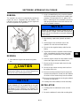
!
WARNING: If incorrectly used this machine can cause sever injury. Those
who use and maintain this machine should be trained in its proper use,
warned of its dangers and should read the entire manual before attempting
to set up, operate, adjust or service the machine.
Litho in the U.S.A. 1/2011
Part Number 4241622
©2011, Jacobsen, A Textron Company. All rights reserved.


SECTION 1
INTRODUCTION
1A General Information........................................................................................................................................ 1
Contents................................................................................................................................................... 1
Index Numbers......................................................................................................................................... 1
Replacement Parts................................................................................................................................... 1
California Proposition 65 Warning............................................................................................................ 2
Specifications........................................................................................................................................... 2
Serial Numbers ........................................................................................................................................ 4
General Cleaning..................................................................................................................................... 4
Safety....................................................................................................................................................... 4
Torque Values .......................................................................................................................................... 5
1

Page Intentionally Blank

INTRODUCTION
1A-1
SECTION 1A. GENERAL INFORMATION
CONTENTS
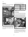
This manual contains repair instructions for major trac-
tor components, attachments, and options. The Table
of Contents at the start of each section lists the con-
tents of that section. Sections are identified by tabs in
the right hand margin.
This manual is to be used in conjunction with the Oper-
ator’s Manual and Parts Catalog.
Normal maintenance, adjustment, and operating pro-
cedures are also covered in the Operator’s Manual and
are only included where appropriate in this Service and
Repair Manual.
Engine repair is not covered in this manual. Refer to
the appropriate engine manufacturer’s instructions for
engine service and repair.
This manual includes all removal, disassembly, inspec-
tion, repair, reassembly, installation, adjustment, and
testing procedures. If you, as the user of this machine,
do not consider yourself or your repair facilities capable
of a given procedure, please contact your Jacobsen
dealer or distributor.
Information, specifications, illustrations, and proce-
dures in this manual are based on information in effect
at the time this manual was published. Improvements
and product changes due to continual advancements
of the product design may cause changes to your prod-
uct that may not be included in this manual. Each man-
ual is reviewed and updated as required to include
changes and product improvements.
Read each section completely before proceeding with
specific repairs in that section. You will minimize errors
by understanding what you will be doing and how the
component relates to others in its system. Lists of
repair tools and materials for each section of the man-
ual are given at the start of that section.
The designations L.H. (left hand) and R.H. (right hand)
are used throughout this manual and refer to the oper-
ator’s left or right when sitting in the normal operating
position.
INDEX NUMBERS
Illustrations showing removal, disassembly, reassem-
bly, and illustration may have index numbers to call out
the sequence of procedures.
Where the sequence of procedures is not important or
self-evident (e.g. linkages, hoses, clamps, etc.) index
numbers are not included.
Repair procedures for items not subject to wear (e.g.
panels, brackets, frames) are not included in this man-
ual except for the general procedures given.
Exercise common sense during disassembly or reas-
sembly; remove only the items required to accomplish
the necessary repair or service.
REPLACEMENT PARTS
Use the appropriate Parts & Maintenance Manual
when ordering replacement parts. Follow the installa-
tion instructions shipped with service parts or kits.
When ordering parts, always give the serial number
and product number and description of the parts
needed.
To eliminate error and speed delivery:
1. Write your NAME and ADDRESS on your order
plainly.
2. Explain WHERE and HOW to make shipment.
3. Give the PRODUCT NUMBER, NAME, and
SERIAL NUMBER that is stamped on the NAME
and SERIAL PLATE of your product.
4. Order by QUANTITY DESIRED, the PART NUM-
BER, and the PART DESCRIPTION.
5. Send your order to or visit your nearest Jacobsen
dealer or distributor.
6. INSPECT ALL SHIPMENTS UPON RECEIPT. If
any parts are damaged or missing, file a claim
with the carrier before accepting.
7. Do not return material to your Jacobsen dealer or
distributor without a letter of explanation. Make a
list of all returned parts, show your name and
address, and include the letter and list with the
shipment. TRANSPORTATION CHARGES MUST
BE PREPAID.
1A

INTRODUCTION
1A-2
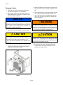
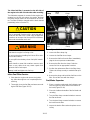
CALIFORNIA PROPOSITION 65
WARNING
SPECIFICATIONS
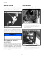
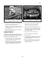
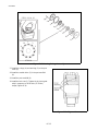
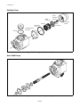
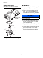
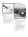
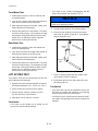
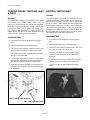
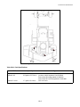
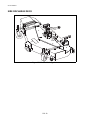
Product Information
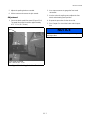
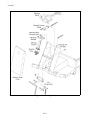
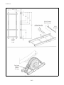
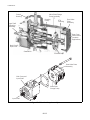
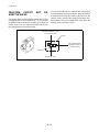
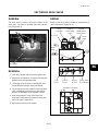
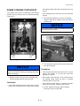
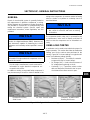
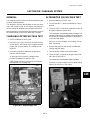
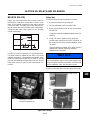
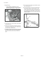
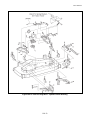
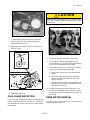
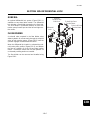
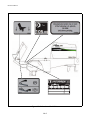
An identification plate, like the one shown, listing the
serial number, is attached to the frame of the tractor
near the center lift arm mount (Figure 1A-2).
Always provide the serial number of the unit when
ordering replacement parts or requesting service infor-
mation.
Figure 1A-1. Serial Plate
Engine
Make/Model..........................D1305-E3B Kubota Diesel
Cylinders..................................................................... 3
Displacement..............................76.95 cu. in. (1261 cc)
Cooling.....Liquid Cooled/w 15 in (381 mm) 8 blade fan
Air filter..............Donaldson dry type w/evacuator valve
Alternator .......................................................... 40 amp
Max rated horsepower ......29.1 (21.7 kW) @ 3000 rpm
Torque......................59.1 ft-lbs (80.1 Nm) @ 2000 rpm
High idle speed ..............................................3220 rpm
Low idle speed...............................................1750 rpm
Fuel capacity....................................9 US gal (34 liters)
Hydraulic System
Capacity...........................................6.8 gal (25.7 liters)
Fluid Type ................................................Jac. (10W30)
Cooling (type)..........................................Hyd. oil cooler
Filter micron rating ......10 micron suction filter w/gauge
Traction System
Drive..Hydrostatic Traction Pump to front wheel motors
in a parallel-series flow to rear wheel motors (4WD).
Forward speed...........................0-10 mph (0-16.1 kph)
Mow speed.....................................0-6 mph (0-9.6 kph)
Reverse speed...............................0-3 mph (0-4.8 kph)
Traction Pump max flow..............18.8 gpm (71.16 lpm)
System relief setting......................... 3625 psi (250 bar)
Deck System
Drive...........Hydraulic gear pump and motor w/ electro/
hydraulic control valve
Deck number & size...(1) 63 in or 72 in side discharge,
60 in or 72 in rear discharge, 60 in or 72 in Envirodeck,
or 60 in Fine-cut Flail
Deck section pump flow...................14 gpm (52.9 lpm)
Deck section relief setting.............3200 psi (220.7 bar)
60 in rear discharge
Number of blades & size per deck............................(3)
................0.25 in (6.4 mm) thick x 21 in (533 mm) long
Blade tip speed ......................12744 ft/min (4189 m/m)
Deck material thickness
.......................................11 gauge 0.1196 in (3.74 mm)
...............................7 gauge skirts 0.1875 in (4.76 mm)
Height of cut range..................1-4.75 in (25.4-121 mm)
63 in side discharge
Number of blades & size per deck............................(3)
................0.25 in (6.4 mm) thick x 22 in (559 mm) long
Blade tip speed ................... 14399 ft/min (4388.8 m/m)
Deck material thickness
.......................................11 gauge 0.1196 in (3.74 mm)
...............................7 gauge skirts 0.1875 in (4.76 mm)
Height of cut range..................1-4.75 in (25.4-121 mm)
72 in side and rear discharge
Number of blades & size per deck............................(3)
................0.25 in (6.4 mm) thick x 25 in (635 mm) long
Blade tip speed ......................14071 ft/min (4289 m/m)
Deck material thickness
.......................................11 gauge 0.1196 in (3.74 mm)
...............................7 gauge skirts 0.1875 in (4.76 mm)
Height of cut range..................1-4.75 in (25.4-121 mm)
72 in Envirodeck
Number of blades & size per deck............................(3)
..........0.25 in (6.4 mm) thick x 24.9 in (632.5 mm) long
Blade tip speed ......................17540 ft/min (5346 m/m)
Deck material thickness....10 gauge 0.135 in (3.4 mm)
Height of cut range..................1-4.75 in (25.4-121 mm)
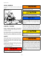
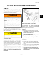
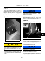
WARNING
Certain vehicle components contain or emit chemi-
cals known to the state of California to cause cancer
and birth defects or other reproductive harm.
!

INTRODUCTION
1A-3
60 in Flail
Number of blades.................................................... 144
Blade speed............................. 8042 ft/min (2451 m/m)
Deck material thickness....10 gauge 0.135 in (3.4 mm)
Height of cut range............................0-4 in (0-102 mm)
Lift System
Type ..........Hand operated single lever hydraulic circuit
Lift system flow................................ 5.9 gpm (22.3 lpm)
Lift system relief setting...................... 915 psi (63 bars)
Steering System
Type .......................Hydrostatic steering to rear wheels
Steering system pump flow............. 5.9 gpm (22.3 lpm)
Steering system relief setting............. 915 psi (63 bars)
Tractor Specifications
Tire size - front......................23 x 10.5 - 12:4 ply rating
......................................(584 mm x 266 mm - 305 mm)
Tire size -rear..........................18 x 18.5 - 8:4 ply rating
......................................(457 mm x 216 mm - 203 mm)
Brakes - service .................... Dynamic braking through
traction circuit
Brakes - parking..............7 x 1.75 in (177.8 x 44.4 mm)
...........................................................Mechanical drum
Turning radius................................. 12.0 in (304.8 mm)
Zero at inside wheel with optional traction-assist brake
on left and right wheel
Sound level rating at operator’s ear (w/72 in deck).......
........................................................................88.1 dBa
Production
60 in ..................................2.8 acres per hour at 6 mph
72 in ..................................3.5 acres per hour at 6 mph
.....................................................(80% of full capacity)
Dimensions
Length with longest deck ................ 122.12 in (310 cm)
Height (to top of hood) .........................44.5 in (113 cm)
Height (to top of ROPS)......................... 82 in (208 cm)
Width (tractor) ........................................ 52 in (132 cm)
Transport width w/ widest deck........... 85.5 in (217 cm)
Ground clearance ................................ 6.5 in (16.5 cm)
Weights
Tractor only
2WD...................................................1440 lbs (653 kg)
4WD...................................................1490 lbs (676 kg)
Decks
63 in side discharge.............................474 lbs (215 kg)
60 in rear discharge .............................390 lbs (177 kg)
72 in side discharge.............................492 lbs (223 kg)
72 in rear discharge .............................505 lbs (229 kg)
72 in Envirodeck...................................485 lbs (220 kg)
60 in Flail..............................................366 lbs (166 kg)
NOTE:
All pump flows and blade tip speeds are at high
idle engine speed and maximum volumetric effi-
ciency.
Accessories and Support Literature
Contact your area Jacobsen dealer for a complete list-
ing of accessories and attachments
Accessories
Canopy / Sunshade Kit
Exhaust Spark Arrestor (Required in California
Leaf Mulcher (For 72 in. Side Discharge Cutting Deck)
Counter Weights
Tie-Down Brackets
Traction Assist / Steering Brakes
High Volume Wheel Motor Kit
Differential Lock Kit - 2WD model only
Support Literature
Safety & Operation Manual
Parts & Maintenance Manual
Engine Parts Catalog
Operator Training Video
Service & Repair Manual
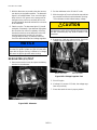
CAUTION
Use of other than Jacobsen authorized parts and
accessories may cause personal injury or damage to
the equipment and will void the warranty.
!

INTRODUCTION
1A-4
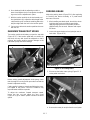
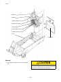
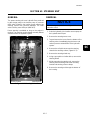
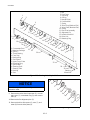
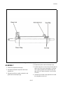
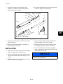
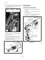
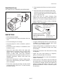
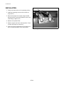
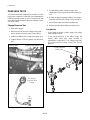
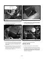
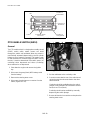
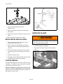
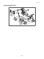
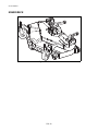
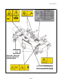
SERIAL NUMBERS
See Figure 1A-2 for location of tractor assembly serial
number.
Figure 1A-2. Serial Number Location
GENERAL CLEANING
Improper cleaning and lubrication of your machine
results in equipment failures. Before any repairs are
undertaken, thoroughly clean the exterior of the com-
ponent to be removed.
Use a clean surface to lay out parts being removed.
Keep lubricants clean and cover containers not being
used. Plug or cap all hydraulic lines and ports to
hydraulic components immediately after disconnecting.
SAFETY
Safety should always be the rule when working on or
with machinery. Always use safe practices and com-
mon sense when using hand or power tools. Use the
suggested procedures in this manual when working
with the tractor.
Throughout this manual signal words will be used to
highlight special procedures. The signal words and
their meanings are as follows:
Any task needing specialized special care when
performing a procedure.
Decals on the machine denote cautions, warnings, and
dangers. These cautions, warnings, and danger decals
must be on the machine at all times. If they become
worn, torn, or painted over, new decals should be
installed as shown in SECTION 14A. of this manual.
DANGER
Imminent hazards which will result in severe per-
sonal injury or death if precautions are not taken.
Serial No. Plate
On Right Side of Frame
!
WARNING
Hazards or unsafe practices which could result in
severe personal injury or death.
CAUTION
Hazards or unsafe practices which may result in per-
sonal injury, or product or property damage.
NOTICE
Indicates a potentially hazardous situation which,
if not avoided, MAY result in property damage. It
may also be used to alert against unsafe
practices.
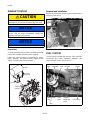
CAUTION
Disconnect leads at the alternator before electric
welding is done on components in common ground
with the engine.
WARNING
This machine is equipped with an interlock system
intended to protect the operator and others from
injury by preventing the engine from starting, unless
the PTO switch is in the “OFF” position, traction
pedal is in the “Neutral” position and the brake is set.
The system also shuts off the engine if the operator
leaves the seat with the PTO switch in the “Cut”
position. In the interest of safe operating conditions,
this machine must never be operated with the inter-
lock relays or interlock system disconnected or mal-
functioning.
!
!
!
!

INTRODUCTION
1A-5
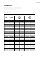
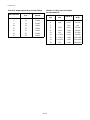
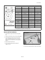
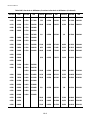
TORQUE VALUES
Torque values are given in the “Torque Specifications
Chart.” Special torque values are called out in illustra-
tions and text throughout this manual.
Torque Specifications – Standard
AMERICAN NATIONAL STANDARD FASTENERS
SIZE UNITS
GRADE 5 GRADE 8
Lubricated Dry Lubricated Dry
#6-32 in-lb (Nm) – 20 (2.3) – –
#8-32 in-lb (Nm) – 24 (2.7) – 30 (3.4)
#10-24 in-lb (Nm) – 35 (4.0) – 45 (5.1)
#10-32 in-lb (Nm) – 40 (4.5) – 50 (5.7)
#12-24 in-lb (Nm) – 50 (5.7) – 65 (7.3)
1/4-20 in-lb (Nm) 75 (8.4) 100 (11.3) 107 (12.1) 143 (16.1)
1/4-28 in-lb (Nm) 85 (9.6) 115 (13.0) 120 (13.5) 163 (18.4)
5/16-18 in-lb (Nm) 157 (17.7) 210 (23.7) 220 (24.8) 305 (34.4)
5/16-24 in-lb (Nm) 173 (19.5) 230 (26.0) 245 (27.6) 325 (36.7)
3/8-16 ft-lb (Nm) 23 (31.1) 31 (42.0) 32 (43.3) 44 (59.6)
3/8-24 ft-lb (Nm) 26 (35.2) 35 (47.4) 37 (50.1) 50 (67.8)
7/16-14 ft-lb (Nm) 37 (50.1) 50 (67.8) 53 (71.8) 70 (94.9)
7/16-20 ft-lb (Nm) 42 (56.9) 55 (74.6) 59 (80.0) 78 (105)
1/2-13 ft-lb (Nm) 57 (77.2) 75 (101) 80 (108) 107 (145)
1/2-20 ft-lb (Nm) 64 (86.7) 85 (115) 90 (122) 120 (162)
9/16-12 ft-lb (Nm) 82 (111) 109 (148) 115 (156) 154 (209)
9/16-18 ft-lb (Nm) 92 (124) 122 (165) 129 (174) 172 (233)
5/8-11 ft-lb (Nm) 113 (153) 151 (204) 159 (215) 211 (286)
5/8-18 ft-lb (Nm) 128 (173) 170 (230) 180 (244) 240 (325)
3/4-10 ft-lb (Nm) 200 (271) 266 (360) 282 (382) 376 (509)
3/4-16 ft-lb (Nm) 223 (302) 298 404 315 (427) 420 (569)
7/8-14 ft-lb (Nm) 355 (481) 473 (641) 500 (678) 668 (905)

INTRODUCTION
1A-6
Torque Specifications – Metric
METRIC FASTENERS
SIZE UNITS
Non
Critical
Fasteners
into
Aluminum
Lubricated Dry Lubricated Dry Lubricated Dry Lubricated Dry
M4 Nm
(in-lb)
––––––3.83
(34)
5.11
(45)
2.0
(18)
M5 Nm
(in-lb)
1.80
(16)
2.40
(21)
4.63
(41)
6.18
(54)
6.63
(59)
8.84
(78)
7.75
(68)
10.3
(910
4.0
(35)
M6 Nm
(in-lb)
3.05
(27)
4.07
(36)
7.87
(69)
10.5
(93)
11.3
(102)
15.0
(133)
13.2
(117)
17.6
(156)
6.8
(60)
M8 Nm
(in-lb)
7.41
(65)
9.98
(88)
19.1
(69)
25.5
(226)
27.3
(241)
36.5
(323)
32.0
(283)
42.6
(377)
17.0
(150)
M10 Nm
(ft-lb)
14.7
(11)
19.6
(14)
37.8
(29)
50.5
(37)
54.1
(40)
72.2
(53)
63.3
(46)
84.4
(62)
33.9
(25)
M12 Nm
(ft-lb)
25.6
(19)
34.1
(25)
66.0
(48)
88.0
(65)
94.5
(70)
125 (92) 110
(81)
147
(108)
61.0
(45)
M14 Nm
(ft-lb)
40.8
(30)
54.3
(40)
105
(77)
140
(103)
150
(110)
200
(147)
175
(129)
234
(172)
94.9
(70)
4.6
8.8
10.9
12.9

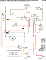
CONTROLS
--1
SECTION 2
CONTROLS
2A Service Tools, Materials, and Specifications................................................................................................... 1
Materials Required................................................................................................................................... 1
Specifications........................................................................................................................................... 1
2B Failure Analysis .............................................................................................................................................. 3
General .................................................................................................................................................... 3
2C Control Adjustments ....................................................................................................................................... 5
General .................................................................................................................................................... 5
Throttle..................................................................................................................................................... 5
Neutral Switch.......................................................................................................................................... 6
Traction Pedal Neutral Adjustment........................................................................................................... 6
Maximum Transport Speed...................................................................................................................... 7
Parking Brake........................................................................................................................................... 7
Brake Interlock Switches.......................................................................................................................... 8
2D Gauges and Instruments ................................................................................................................................ 9
Repair....................................................................................................................................................... 9
2

CONTROLS
-0
Page Intentionally Blank

CONTROLS
2A-1
SECTION 2A. SERVICE TOOLS, MATERIALS, AND SPECIFICATIONS
MATERIALS REQUIRED
l
SPECIFICATIONS
Throttle
Engine low idle speed.................................... 1750 rpm
Engine high idle speed................................... 3220 rpm
Neutral Switch
Neutral switch ......................................Normally closed
Traction Pedal
Transport speed.............................10 mph (16.1 km/h)
Parking Brake
Brake pedal free play......0.750 to 1.5 in (19 to 38 mm)
Parking brake switches..........................Normally open
Tools required:
Standard automotive hand tools
Cleaning
materials:
Stoddard solvent or equivalent
Detergent and water
Lubricants:
Refer to Section 11
2A

CONTROLS
2A-2
Page Intentionally Blank

CONTROLS
2B-3
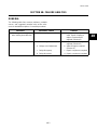
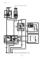
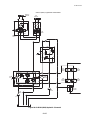
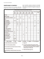
SECTION 2B. FAILURE ANALYSIS
GENERAL
The following table lists common problems, probable
causes, and suggested remedies with section refer-
ences to detailed descriptions of remedial procedures.
PROBLEM PROBABLE CAUSE REMEDY
1. Engine does not turn over a. Not in neutral
b. Electrical fault
c. Neutral start switch not
adjusted or faulty
d. Dead battery
a. Check neutral position
b. See Electrical Failure Analy-
sis (Section 10B)
c. Adjust (Section 2C)
Check (Section 10G)
d. Charge battery or replace as
necessary
2. Engine speed does not
increase when throttle con-
trol is moved
a. Throttle control is not properly
adjusted
b. Throttle control is broken
a. Adjust (Section 2C)
b. Repair or replace
(Section 2C)
3. The unit “creeps” in either
direction when the treadle
pedal is not depressed
a. Traction pedal linkage out of
adjustment
b. Centering spring out of
adjustment
a. Adjust traction (Section 2C)
b. Adjust centering spring
4. Parking brake fails a. Brake not adjusted
b. Worn brake shoes
c. Damaged or broken linkage
a. Adjust brake (Section 2C)
b. Replace pads (Section 5C)
c. Repair as necessary
5. Mower deck does not lift or
lower properly as lever is
activated
a. Control valve leaking or
defective
b. System relief valve too low
c. Faulty lift cylinder
d. Faulty charge pump
a. Test valve (Section 8L)
Repair valve (Section 8I)
b. Adjust (Section 8L)
c. Test cylinder (Section 8L and
Section 8M)
d. Test pump (Section 8M)
6. Slow traction speed a. Engine rpm too low
b. Pedal linkage not adjusted
c. Parking brake not releasing
d. Faulty hydro
a. Adjust (Section 2C)
b. Adjust (Section 2C)
c. Adjust (Section 2C)
d. Test hydro pump
(Section 8M)
2B

CONTROLS
2B-4
Page Intentionally Blank
Page is loading ...
Page is loading ...
Page is loading ...
Page is loading ...
Page is loading ...
Page is loading ...
Page is loading ...
Page is loading ...
Page is loading ...
Page is loading ...
Page is loading ...
Page is loading ...
Page is loading ...
Page is loading ...
Page is loading ...
Page is loading ...
Page is loading ...
Page is loading ...
Page is loading ...
Page is loading ...
Page is loading ...
Page is loading ...
Page is loading ...
Page is loading ...
Page is loading ...
Page is loading ...
Page is loading ...
Page is loading ...
Page is loading ...
Page is loading ...
Page is loading ...
Page is loading ...
Page is loading ...
Page is loading ...
Page is loading ...
Page is loading ...
Page is loading ...
Page is loading ...
Page is loading ...
Page is loading ...
Page is loading ...
Page is loading ...
Page is loading ...
Page is loading ...
Page is loading ...
Page is loading ...
Page is loading ...
Page is loading ...
Page is loading ...
Page is loading ...
Page is loading ...
Page is loading ...
Page is loading ...
Page is loading ...
Page is loading ...
Page is loading ...
Page is loading ...
Page is loading ...
Page is loading ...
Page is loading ...
Page is loading ...
Page is loading ...
Page is loading ...
Page is loading ...
Page is loading ...
Page is loading ...
Page is loading ...
Page is loading ...
Page is loading ...
Page is loading ...
Page is loading ...
Page is loading ...
Page is loading ...
Page is loading ...
Page is loading ...
Page is loading ...
Page is loading ...
Page is loading ...
Page is loading ...
Page is loading ...
Page is loading ...
Page is loading ...
Page is loading ...
Page is loading ...
Page is loading ...
Page is loading ...
Page is loading ...
Page is loading ...
Page is loading ...
Page is loading ...
Page is loading ...
Page is loading ...
Page is loading ...
Page is loading ...
Page is loading ...
Page is loading ...
Page is loading ...
Page is loading ...
Page is loading ...
Page is loading ...
Page is loading ...
Page is loading ...
Page is loading ...
Page is loading ...
Page is loading ...
Page is loading ...
Page is loading ...
Page is loading ...
Page is loading ...
Page is loading ...
Page is loading ...
Page is loading ...
Page is loading ...
Page is loading ...
Page is loading ...
Page is loading ...
Page is loading ...
Page is loading ...
Page is loading ...
Page is loading ...
Page is loading ...
Page is loading ...
Page is loading ...
Page is loading ...
Page is loading ...
Page is loading ...
Page is loading ...
Page is loading ...
Page is loading ...
Page is loading ...
Page is loading ...
Page is loading ...
Page is loading ...
Page is loading ...
Page is loading ...
Page is loading ...
Page is loading ...
Page is loading ...
Page is loading ...
Page is loading ...
Page is loading ...
Page is loading ...
Page is loading ...
Page is loading ...
Page is loading ...
Page is loading ...
Page is loading ...
Page is loading ...
Page is loading ...
Page is loading ...
Page is loading ...
Page is loading ...
Page is loading ...
Page is loading ...
Page is loading ...
Page is loading ...
Page is loading ...
Page is loading ...
Page is loading ...
Page is loading ...
Page is loading ...
Page is loading ...
Page is loading ...
Page is loading ...
Page is loading ...
Page is loading ...
Page is loading ...
Page is loading ...
Page is loading ...
Page is loading ...
Page is loading ...
Page is loading ...
Page is loading ...
Page is loading ...
Page is loading ...
Page is loading ...
Page is loading ...
Page is loading ...
Page is loading ...
Page is loading ...
Page is loading ...
Page is loading ...
Page is loading ...
Page is loading ...
Page is loading ...
Page is loading ...
Page is loading ...
Page is loading ...
Page is loading ...
Page is loading ...
Page is loading ...
Page is loading ...
Page is loading ...
Page is loading ...
Page is loading ...
Page is loading ...
Page is loading ...
Page is loading ...
Page is loading ...
Page is loading ...
Page is loading ...
Page is loading ...
Page is loading ...
Page is loading ...
Page is loading ...
Page is loading ...
Page is loading ...
Page is loading ...
Page is loading ...
Page is loading ...
Page is loading ...
Page is loading ...
Page is loading ...
Page is loading ...
Page is loading ...
Page is loading ...
Page is loading ...
Page is loading ...
Page is loading ...
Page is loading ...
Page is loading ...
Page is loading ...
Page is loading ...
Page is loading ...
Page is loading ...
Page is loading ...
Page is loading ...
Page is loading ...
Page is loading ...
Page is loading ...
Page is loading ...
Page is loading ...
Page is loading ...
Page is loading ...
Page is loading ...
Page is loading ...
Page is loading ...
Page is loading ...
Page is loading ...
Page is loading ...
Page is loading ...
Page is loading ...
Page is loading ...
Page is loading ...
Page is loading ...
Page is loading ...
Page is loading ...
Page is loading ...
Page is loading ...
Page is loading ...
Page is loading ...
Page is loading ...
Page is loading ...
Page is loading ...
Page is loading ...
Page is loading ...
Page is loading ...
Page is loading ...
Page is loading ...
Page is loading ...
Page is loading ...
Page is loading ...
Page is loading ...
Page is loading ...
Page is loading ...
Page is loading ...
Page is loading ...
Page is loading ...
Page is loading ...
Page is loading ...
Page is loading ...
Page is loading ...
Page is loading ...
Page is loading ...
Page is loading ...
Page is loading ...
Page is loading ...
Page is loading ...
Page is loading ...
Page is loading ...
Page is loading ...
Page is loading ...
Page is loading ...
Page is loading ...
Page is loading ...
Page is loading ...
Page is loading ...
Page is loading ...
Page is loading ...
Page is loading ...
Page is loading ...
Page is loading ...
Page is loading ...
Page is loading ...
Page is loading ...
Page is loading ...
Page is loading ...
Page is loading ...
Page is loading ...
Page is loading ...
Page is loading ...
Page is loading ...
Page is loading ...
Page is loading ...
Page is loading ...
Page is loading ...
Page is loading ...
Page is loading ...
Page is loading ...
Page is loading ...
Page is loading ...
Page is loading ...
-
 1
1
-
 2
2
-
 3
3
-
 4
4
-
 5
5
-
 6
6
-
 7
7
-
 8
8
-
 9
9
-
 10
10
-
 11
11
-
 12
12
-
 13
13
-
 14
14
-
 15
15
-
 16
16
-
 17
17
-
 18
18
-
 19
19
-
 20
20
-
 21
21
-
 22
22
-
 23
23
-
 24
24
-
 25
25
-
 26
26
-
 27
27
-
 28
28
-
 29
29
-
 30
30
-
 31
31
-
 32
32
-
 33
33
-
 34
34
-
 35
35
-
 36
36
-
 37
37
-
 38
38
-
 39
39
-
 40
40
-
 41
41
-
 42
42
-
 43
43
-
 44
44
-
 45
45
-
 46
46
-
 47
47
-
 48
48
-
 49
49
-
 50
50
-
 51
51
-
 52
52
-
 53
53
-
 54
54
-
 55
55
-
 56
56
-
 57
57
-
 58
58
-
 59
59
-
 60
60
-
 61
61
-
 62
62
-
 63
63
-
 64
64
-
 65
65
-
 66
66
-
 67
67
-
 68
68
-
 69
69
-
 70
70
-
 71
71
-
 72
72
-
 73
73
-
 74
74
-
 75
75
-
 76
76
-
 77
77
-
 78
78
-
 79
79
-
 80
80
-
 81
81
-
 82
82
-
 83
83
-
 84
84
-
 85
85
-
 86
86
-
 87
87
-
 88
88
-
 89
89
-
 90
90
-
 91
91
-
 92
92
-
 93
93
-
 94
94
-
 95
95
-
 96
96
-
 97
97
-
 98
98
-
 99
99
-
 100
100
-
 101
101
-
 102
102
-
 103
103
-
 104
104
-
 105
105
-
 106
106
-
 107
107
-
 108
108
-
 109
109
-
 110
110
-
 111
111
-
 112
112
-
 113
113
-
 114
114
-
 115
115
-
 116
116
-
 117
117
-
 118
118
-
 119
119
-
 120
120
-
 121
121
-
 122
122
-
 123
123
-
 124
124
-
 125
125
-
 126
126
-
 127
127
-
 128
128
-
 129
129
-
 130
130
-
 131
131
-
 132
132
-
 133
133
-
 134
134
-
 135
135
-
 136
136
-
 137
137
-
 138
138
-
 139
139
-
 140
140
-
 141
141
-
 142
142
-
 143
143
-
 144
144
-
 145
145
-
 146
146
-
 147
147
-
 148
148
-
 149
149
-
 150
150
-
 151
151
-
 152
152
-
 153
153
-
 154
154
-
 155
155
-
 156
156
-
 157
157
-
 158
158
-
 159
159
-
 160
160
-
 161
161
-
 162
162
-
 163
163
-
 164
164
-
 165
165
-
 166
166
-
 167
167
-
 168
168
-
 169
169
-
 170
170
-
 171
171
-
 172
172
-
 173
173
-
 174
174
-
 175
175
-
 176
176
-
 177
177
-
 178
178
-
 179
179
-
 180
180
-
 181
181
-
 182
182
-
 183
183
-
 184
184
-
 185
185
-
 186
186
-
 187
187
-
 188
188
-
 189
189
-
 190
190
-
 191
191
-
 192
192
-
 193
193
-
 194
194
-
 195
195
-
 196
196
-
 197
197
-
 198
198
-
 199
199
-
 200
200
-
 201
201
-
 202
202
-
 203
203
-
 204
204
-
 205
205
-
 206
206
-
 207
207
-
 208
208
-
 209
209
-
 210
210
-
 211
211
-
 212
212
-
 213
213
-
 214
214
-
 215
215
-
 216
216
-
 217
217
-
 218
218
-
 219
219
-
 220
220
-
 221
221
-
 222
222
-
 223
223
-
 224
224
-
 225
225
-
 226
226
-
 227
227
-
 228
228
-
 229
229
-
 230
230
-
 231
231
-
 232
232
-
 233
233
-
 234
234
-
 235
235
-
 236
236
-
 237
237
-
 238
238
-
 239
239
-
 240
240
-
 241
241
-
 242
242
-
 243
243
-
 244
244
-
 245
245
-
 246
246
-
 247
247
-
 248
248
-
 249
249
-
 250
250
-
 251
251
-
 252
252
-
 253
253
-
 254
254
-
 255
255
-
 256
256
-
 257
257
-
 258
258
-
 259
259
-
 260
260
-
 261
261
-
 262
262
-
 263
263
-
 264
264
-
 265
265
-
 266
266
-
 267
267
-
 268
268
-
 269
269
-
 270
270
-
 271
271
-
 272
272
-
 273
273
-
 274
274
-
 275
275
-
 276
276
-
 277
277
-
 278
278
-
 279
279
-
 280
280
-
 281
281
-
 282
282
-
 283
283
-
 284
284
-
 285
285
-
 286
286
-
 287
287
-
 288
288
-
 289
289
-
 290
290
-
 291
291
-
 292
292
-
 293
293
-
 294
294
-
 295
295
-
 296
296
-
 297
297
-
 298
298
-
 299
299
-
 300
300
-
 301
301
-
 302
302
-
 303
303
-
 304
304
-
 305
305
-
 306
306
-
 307
307
-
 308
308
-
 309
309
-
 310
310
-
 311
311
-
 312
312
-
 313
313
-
 314
314
-
 315
315
-
 316
316
-
 317
317
-
 318
318
-
 319
319
-
 320
320
-
 321
321
-
 322
322
-
 323
323
-
 324
324
-
 325
325
-
 326
326
-
 327
327
-
 328
328
-
 329
329
-
 330
330
-
 331
331
-
 332
332


Ransomes 69168, 69169 User manual
- Category
- Lawnmowers
- Type
- User manual
Ask a question and I''ll find the answer in the document
Finding information in a document is now easier with AI
in other languages
Related papers
-
Textron 4171722 User manual
-
Ransomes 67862, 67863 Owner's manual
-
-
-
-
-
-
-
-
Other documents
-
AmeriHome BSSS1 Assembly Instructions
-
 PMI PDP12-1 Operating instructions
-
Toro Temperature Sender Kit, Groundsmaster 1000L Installation guide
-
Abus 500107032000 Datasheet
-
-
 Ferris 5901703 Product information
-
 Ferris 5901703 Product information
-
Cub Cadet ZTXS5 60 Ultima Series User manual
-
Broan H6HK, 25 Kw 240V,1-Phase Electric Heater Kit Product information
-


