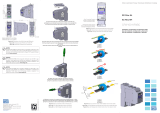
WEG CFW100-IOAR I/O Expansion Module User guide
- Category
- Electrical relays
- Type
- User guide
This manual is also suitable for

I/O Expansion Modules
Módulo de Expansión de I/O
Módulo de Expansão de I/O
CFW100
Installation, Configuration and Operation Guide
Guía de Instalación, Configuración y Operación
Guia de Instalação, Configuração e Operação
Motors | Automation | Energy | Transmission & Distribution | Coatings
Page is loading ...

Summary / Índice
English
EspañolPortuguês
SUMMARY
1 SAFETY INFORMATION ...............................5
1.1 SAFETY WARNINGS ....................................5
1.2 PRELIMINARY RECOMMENDATIONS .......5
2 GENERAL INFORMATION ...........................5
3 CONTENT OF THE PACKAGE ....................5
4 INSTALLATION OF THE ACCESSORY .......5
5 CONFIGURATIONS ......................................6
APPENDIX A – FIGURES ............................... 17
ÍNDICE
1 INFORMACIONES DE SEGURIDAD ...........9
1.1 AVISOS DE SEGURIDAD ..............................9
1.2 RECOMENDACIONES PRELIMINARES .....9
2 INFORMACIONES GENERALES .................9
3 CONTENIDO DEL EMBALAJE ....................9
4 INSTALACIÓN DEL ACCESORIO................9
5 CONFIGURACIONES .................................10
ANEXO A – FIGURAS .....................................17
ÍNDICE
1 INFORMAÇÕES DE SEGURANÇA ............13
1.1 AVISOS DE SEGURANÇA .......................... 13
1.2 RECOMENDAÇÕES PRELIMINARES ....... 13
2 INFORMAÇÕES GERAIS ...........................13
3 CONTEÚDO DA EMBALAGEM ..................13
4 INSTALAÇÃO DO ACESSÓRIO .................13
5 CONFIGURAÇÕES .....................................14
ANEXO A – FIGURAS .....................................17
Page is loading ...

I/O Expansion Modules
English
CFW100 | 5
1 SAFETY INFORMATION
1.1 SAFETY WARNINGS
NOTE!
Only use the I/O expansion module
(CFW100-IOAR) on WEG CFW100 series
inverters with firmware from version V2.0X
up (see P023).
It is recommended to read the CFW100
user manual before installing or operating
this accessory.
This guide contains important information
regarding the proper understanding and
correct operation of this module.
1.2 PRELIMINARY RECOMMENDATIONS
ATTENTION!
Always disconnect the general power
supply before connecting or disconnecting
the accessories of the CFW100 frequency
inverter.
Wait for at least ten minutes for the full
discharge of the power capacitors.
2 GENERAL INFORMATION
This guide provides directions for the installation,
configuration and operation of the I/O expansion module
(CFW100-IOAR).
3 CONTENT OF THE PACKAGE
Upon receiving the product, check if the package
contains:
Accessory in anti-static package.
Installation, configuration and operation guide.
4 INSTALLATION OF THE ACCESSORY
The CFW100-IOAR is easily connected to the CFW100
frequency inverter by means of the plug-and-play
concept. The procedures below must be observed for

I/O Expansion Modules
English
6 | CFW100
the proper installation and start-up:
1. With the inverter de-energized, remove the front
cover of the Inverter (Figure A1 on page 17).
2. Fit the accessory to be installed as shown in Figure
A1 on page 17.
3. Power up the inverter.
5 CONFIGURATIONS
The CFW100-IOAR connections must be done to the
I/O expansion connector as per Table 1 on page 6.
Table 1: Signals of the I/O expansion connector
Connector Description Specifications
6 GND Reference 0 V Not interconnected to PE.
7 AI1 Analog
Input 1
1 isolated input. Levels:
(0 to 10) V or (0 to 20) mA
or (4 to 20) mA.
Resolution: 10 bits.
Impedance: 100 kΩ for
voltage input, 500 Ω for
current input.
Programmable function.
Maximum accepted
voltage: 30 Vdc.
8 + 10 V Reference
+ 10 V for
potentiometer
Power supply: + 10 Vdc.
Maximum capacity:
50 mA.
Tolerance: ±5 %.
9 DO1-RL-C Digital Output
1 (Common
point of relay 1)
1 relay with NO contact.
Maximum voltage:
240 Vac.
Maximum current: 0.5 A.
Minimum current: >1 uA
Programmable
functions
10 DO1-RL-NO Digital Output
1 (NO point of
relay 1)
Counter-
clockwise
≥5 k
Clockwise
The location of switch S1 to select the type of analog
input signal can be better viewed in Figure A2 on page
18 and must be configured according to Table 2 on
page 7. In order to use the analog input with signal
in current, switch S1 and related parameters must be set
according to Table 2 on page 7. For further details,
refer to chapter 12 of the CFW100 programming manual.

I/O Expansion Modules
English
CFW100 | 7
Table 2: Configuration of switch S1 to select the type of
analog input signal on the CFW100-IOAR
Input Signal
Setting of
Switch S1
Signal
Range
Parameter
Setting
AI1
Voltage
S1 = OFF
(Position I)
0 ... 10 V P233 = 0 or 2
Current
S1 = ON
(Position II)
0 ... 20 mA P233 = 0 or 2
4 ... 20 mA P233 = 1 or 3
NOTE!
The firmware version of the CFW100-IOAR
accessory can be viewed in parameter P024
of the CFW100 inverter.
ATTENTION!
For the proper operation of the CFW100
inverter with the CFW100-IOAR module,
parameters P308, P310, P311 and P312 must
be programmed with the factory settings.
For further details, refer to the programming
manual of the CFW100 V2.0X or up.

I/O Expansion Modules
English
8 | CFW100
Page is loading ...
Page is loading ...
Page is loading ...
Page is loading ...
Page is loading ...
Page is loading ...
Page is loading ...
Page is loading ...
Page is loading ...
Page is loading ...
Page is loading ...
Page is loading ...
-
 1
1
-
 2
2
-
 3
3
-
 4
4
-
 5
5
-
 6
6
-
 7
7
-
 8
8
-
 9
9
-
 10
10
-
 11
11
-
 12
12
-
 13
13
-
 14
14
-
 15
15
-
 16
16
-
 17
17
-
 18
18
-
 19
19
-
 20
20
WEG CFW100-IOAR I/O Expansion Module User guide
- Category
- Electrical relays
- Type
- User guide
- This manual is also suitable for
Ask a question and I''ll find the answer in the document
Finding information in a document is now easier with AI
in other languages
Related papers
-
WEG CFW100 User manual
-
WEG CFW100 Quick start guide
-
 Automation Direct CFW100-IOP Potentiometer Reference Module User guide
-
Automation Direct CFW100 User guide
-
WEG CFW100 User guide
-
Automation Direct CFW100-IOD I/O Expansion Module NPN/PNP Digital Inputs User guide
-
WEG CFW100 User guide
-
 Automation Direct CFW100-KFABC-S1 / -S2 RFI Filter Kit User guide
-
WEG CFW100 Programming Manual
-
WEG CFW100 Installation guide
Other documents
-
Arctic P311 Welcome Manual
-
Arctic P311 User manual
-
Arctic P311 User manual
-
Tripp Lite SmartOnline 208V SV-Series 3-Phase Modular UPS Systems Owner's manual
-
Comelit 8451V Quadra Video Owner's manual
-
Tripp Lite SmartOnline 208V SV-Series 3-Phase Modular UPS Systems Owner's manual
-
Carrier 30AWH006HB Installation guide
-
ASROCK ALIVENF6G-DVI Installation guide
-
Dell PowerEdge 300 Quick start guide
-
Tripp Lite SmartOnline® 400V SVX-Series 3-Phase Modular UPS Systems Owner's manual


