Liberty Pumps LEH102A2 Installation guide

Type
Installation guide
7000 Apple Tree Avenue
Bergen, NY 14416
Phone: (800) 543-2550
Fax: (585) 494-1839
www.libertypumps.com
IMPORTANT:
Prior to installation, record Model, Serial Number, and
Code Number from pump nameplate for future reference.
MODEL ______________________
SERIAL ______________________
CODE ______________________
INSTALLATION
DATE ______________________
©Copyright 2015 Liberty Pumps Inc. All rights reserved
Contents
1.) General Information
2.) The Basin
3.) Installation
4.) Electrical Service and Operation
5.) Maintenance and Troubleshooting
6.) Warranty
Installation Manual 7034000L
LE and LEH Series Sewage Pumps
Models
LE40-Series 4/10 HP
LE50-Series 1/2 HP
LE70-Series 3/4 HP
LE100-Series 1 HP
LEH100-Series 1 HP
LEH150-Series 1.5 HP
LEH200-Series 2 HP
*Do not throw away or lose this manual.
©Copyright 2015 Liberty Pumps Inc. All rights reserved 2
Before Installation, read the following instructions carefully. Each Liberty pump is individually factory tested to assure
proper performance. By closely following these instructions, potential operating problems should be eliminated, providing
years of trouble-free service.
Risk of electric shock. Always disconnect the pump from the power source before handling or making adjustments.
The electrical connections and wiring for a pump installation should only be made by qualified personnel.
This pump is supplied with a grounding conductor and grounding-type attachment plug. To reduce the risk of electric
shock, be certain that it is connected only to a properly grounded, grounding-type receptacle.
Always wear rubber boots when water is on the floor and you must unplug the pump.
DO NOT bypass grounding wires or remove ground prong from attachment plugs.
DO NOT use an extension cord.
This pump requires a separate, properly fused and grounded branch circuit. Make sure the power source is properly
sized for the voltage and amperage requirements of the pump, as noted on the nameplate.
The electrical outlet shall be within the length limitations of the pump power cord, and at least 4 feet above floor level
to minimize possible hazards from flood conditions.
The installation must be in accordance with the National Electric Code, Uniform Plumbing Code, International
Plumbing Code, as well as all applicable local codes and ordinances.
Sump and sewage pumps often handle materials which could cause illness or disease. Wear adequate protective
clothing when working on a used pump or piping.
Never enter a pump basin after it has been used. Sewage and effluent can emit several gases which are poisonous.
Keep clear of suction and discharge openings. To prevent injury, never insert fingers into pump while it is plugged in.
DO NOT use this product for flammable or corrosive liquid.
DO NOT use this product in applications where human contact with the pumped fluid is common (such as swimming
pools, fountains, etc.)
NEVER dispose of materials such as paint thinner or other chemicals down drains, as they can chemically attack and
damage pump components, potentially causing product malfunction or failure.
DO NOT use pumps in water over 140F (60C).
DO NOT use pumps in mud, sand, cement, oil or chemicals.
DO NOT modify the pump in any way.
DO NOT lift or carry pump by power cord.
DO NOT remove any tags from pump or cords.
If pump is installed during construction before power is available, it must be protected from the environment to prevent
water from entering through the cord plug end, etc.
Disconnect old pump from power source before handling.
Separate the discharge pipe at either the check valve or at the union. If neither a check valve nor a union is part of the
existing discharge pipe, cut the pipe with a hacksaw and remove the pump (A union or check valve will need to be
installed at this cut).
1. General Information
©Copyright 2015 Liberty Pumps Inc. All rights reserved 3
Note: Manual models (“M” suffix) and 3 phase models, as designated above, require a separate approved pump control device or
panel for automatic operation. Operation of these models will be according to the control selected. Make sure the electrical
specifications of the control selected properly match the electrical specifications of the pump. 3 phase models require overload
elements selected or adjusted in accordance with the control or panel instructions.
Automatic pumps have a float switch preassembled. The optional (V) denotes that the pump is available with a vertical float.
MODEL SPECIFICATIONS
Model
Volts
Phase
Full Load
Amps
Solids
Handling
FNPT
Discharge
Automatic or
Manual*
Shut-off
Head
LE41A(V)
115
1
12
2”
2”
Automatic
19
*LE41M
115
1
12
2”
2”
Manual*
19
LE51A(V)
115
1
12
2”
2”
Automatic
25’
*LE51M
115
1
12
2”
2”
Manual*
25’
LE52A
208-230
1
6.8
2”
2”
Automatic
25’
*LE52M
208-230
1
6.8
2”
2”
Manual*
25’
LE71A
115
1
12
2”
2” or 3”
Automatic
28’
*LE71M
115
1
12
2”
2” or 3”
Manual*
28’
LE72A
208-230
1
6
2”
2” or 3”
Automatic
28’
*LE72M
208-230
1
6
2”
2” or 3”
Manual*
28’
*LE73M
208-230
3
4.1
2”
2” or 3”
Manual*
28’
*LE74M
440-480
3
2.1
2”
2” or 3”
Manual*
28’
LE102A
208-230
1
8
2”
2” or 3”
Automatic
36’
*LE102M
208-230
1
8
2”
2” or 3”
Manual*
36’
*LE103M
208-230
3
5.3
2”
2” or 3”
Manual*
36’
*LE104M
440-480
3
2.5
2”
2” or 3”
Manual*
36’
*LE105M
575
3
1.9
2”
2” or 3”
Manual*
36’
NOTE: LEH100-Series High-Head pumps require a minimum application of 15’ head.
LEH102A
230
1
12
2”
2” or 3”
Automatic
53’
*LEH102M
230
1
12
2”
2” or 3”
Manual*
53’
*LEH103M
208-230
3
9
2”
2” or 3”
Manual*
53’
*LEH104M
440-480
3
4.5
2”
2” or 3”
Manual*
53’
*LEH105M
575
3
3.3
2”
2” or 3”
Manual*
53’
NOTE: LEH150 & LEH200 Series High-Head pumps require a minimum application of 20’ head.
LEH152A
208-230
1
15
2”
2” or 3”
Automatic
70’
*LEH152M
208-230
1
15
2”
2” or 3”
Manual*
70’
*LEH153M
208-230
3
10.6
2”
2” or 3”
Manual*
70’
*LEH154M
440-480
3
5.3
2”
2” or 3”
Manual*
70’
*LEH155M
575
3
4.9
2”
2” or 3”
Manual*
70’
*LEH202M
230
1
18
2”
2” or 3”
Manual*
83’
*LEH203M
208-230
3
13.2
2”
2” or 3”
Manual*
83’
*LEH204M
440-480
3
6.6
2”
2” or 3”
Manual*
83’
*LEH205M
575
3
5.5
2”
2” or 3”
Manual*
83’
WARNING:
Always use a replacement power cord assembly of the same length and type as originally installed on the Liberty product. Using a
cord of improper gauge or length may lead to exceeding the electrical rating of the cord and could result in death, injury, fire or other
significant failure.
©Copyright 2015 Liberty Pumps Inc. All rights reserved 4
The basin required for both effluent and sewage applications must be sealed and vented to meet health and plumbing code
requirements. These pumps are not to be installed in locations classified as hazardous in accordance with the National Electric Code,
ANSI/NFPA 70. The diameter should be a minimum of 18" and the depth a minimum of 24". (These are minimum requirements. A
larger basin may be required in both effluent and sewage applications depending on local codes and the number of fixture units
entering the system. Check with the local authorities or contact Liberty Pumps if you are unsure of the proper basin size.) Installation
should be at a sufficient depth to ensure that all plumbing is below the frost line. If this is not feasible, remove the check valve and size
the basin and/or adjust pump differential to accommodate the additional backflow volume.
A. Excavation: Excavate the hole as small as possible, with a minimum recommended 8" diametrical clearance around the tank.
Never place the basin directly in contact with rocks or other sharp objects. Place only fine, 1/8" to 3/4" pea gravel or 1/8" to 1/2"
washed, crushed stone as bedding between the basin and the hole walls. Do not use sand or native soil as backfill. Properly
compact underneath the basin to provide a solid, level base that can support the weight of the filled basin.
B. Inlet Connection & Initial Backfill: Only fine, 1/8" to 3/4" pea gravel or 1/8" to 1/2" washed, crushed stone should be used
around the bottom of the basin to hold it in place. Do not use sand or native soil as backfill. Make the inlet connection as required
for your basin.
Liberty P370 & P380-Series: The Liberty P370-& P380 Series basins have a 4" inlet molded to the side of the tank. This inlet is
sized to accept a 4" no-hub type coupling. Connect the gravity drainage line from the fixtures to this
hub.
Other Basins: Other Liberty basins provide a 4" caulking hub or pipe grommet inlet. Hubs utilize caulking material or
rubber donuts; grommets are a simple slip-fit. Connect the gravity drainage line from the fixtures to this
opening. (Other inlet sizes available – consult factory.)
C. Final Backfill: Large rocks, clods, and foreign objects should be kept out of the backfill material. Only fine, 1/4" to 3/4" pea
gravel, or 1/8" to 1/2" washed, crushed stone is recommended. Do not use sand or native soil as backfill. Mound the backfill
slightly and allow for natural settling. Provide access to the basin cover for maintenance and service.
Do not exert heavy pressure or run heavy equipment on the backfill material as this could cause the
tank to collapse.
For 3-Phase pumps, check for proper rotation before installing pump into basin (see Fig. 1).
If the basin is already installed, proceed
to Installation of the Pump.
2. The Basin
3. Installation of the Pump
Check three phase pumps for proper
rotation prior to installing pump(s) in
basin. To change rotation, reverse any
two of the three power leads to the
pump. Code the wires for
reconnection after installation.
Bottom View
Fig. 1 Proper impeller rotation,
three phase models
©Copyright 2015 Liberty Pumps Inc. All rights reserved 5
Fig. 3 – Typical Installation Duplex System
This is a recommended installation only. Variations may apply.
Fig. 2 – Typical Installation Simplex System
This is a recommended installation only. Variations may apply.
Liberty pre-assembled sewage systems come with the pump(s) already pre-mounted in the basin. The discharge pipe(s) already exit
through the cover, ready to be connected to the remaining discharge line. If you have purchased a pre-assembled system, disregard
steps A and B below.
A. Simplex (One Pump) Systems (see Fig. 2):
Set the pump in place making sure the float
has adequate clearance to the side wall of the
basin. If an optional control device or float is
used, follow the directions for mounting that
accompany the optional control. Minimum
pump turn off level should not be set below 6”.
Connect the discharge pipe to the pump's
threaded discharge. IMPORTANT: Do not
reduce the discharge pipe size below that
which is provided on the pump. Sewage
pumps should not be smaller than 2". In
some applications, it may be necessary to
increase the pipe size to reduce friction
losses. Contact Liberty Pumps or other
qualified person if you have questions
regarding proper pipe sizes and flow rates.
Mount the basin cover provided, making sure it
is properly sealed. (This is a recommended
installation. Variations may apply.)
B. Duplex (Two Pump) Systems (see Fig. 3): Set both
pumps in place in the bottom of the basin. The duplex
control used will include 3 or 4 floats that will either be
tethered to one of the discharge pipes or to an
independent rod hung from the cover. Follow the
instructions provided with your duplex control device.
Minimum pump turn off level should not be set below
6”. Make sure all floats move freely. Connect an
individual discharge pipe to each pump.
IMPORTANT: Do not reduce the discharge pipe
size below that which is provided on the pump.
Sewage pumps should not be reduced below 2". In
some applications, it may be necessary to increase
the pipe size to reduce friction losses. Contact Liberty
Pumps or other qualified person if you have any
questions regarding proper pipe sizes and flow rates.
To eliminate fluid recycling in duplex installations, it is
necessary to have a check valve on each discharge
line prior to tying the two discharges into one common
line. Depending on the height of your basin, the check
valves may either be installed inside or outside the
basin. Mount the basin covers, making sure they
are properly sealed.
©Copyright 2015 Liberty Pumps Inc. All rights reserved 6
C. Installation of Remaining Discharge (Simplex): After the pump has been mounted and the cover sealed, install
the remaining discharge line. A union should be installed just above the cover to facilitate pump removal if
necessary. A check valve is recommended after the union to prevent the backflow of liquid after each pumping
cycle. A gate valve should follow the check valve to allow periodic cleaning of the check valve or removal of the
pump. The remainder of the discharge line should be as short as possible with a minimum number of turns, to
minimize friction head loss. Do not restrict the discharge to below 2" in sewage applications. Larger pipe sizes may
be required to eliminate friction head loss over long runs. Contact Liberty Pumps or other qualified person if there
are questions regarding proper pipe size and flow rates. Vent: A connection is provided on top of the cover which
must be piped to the existing building vent, or extended outside on its own standpipe. The vent size should be in
accordance with applicable codes, but not less than the discharge size. Some LE and LEH-Series pumps come
equipped with an air bleed hole to help prevent air lock. A small spray of water from this hole is normal
while pump is running.
D. Installation of Remaining Discharge (Duplex): Unions or flexible connectors should be installed just above the
cover on each discharge to facilitate removal of the pump if necessary. Free-flow swing check valves should be
installed on each discharge after the union and prior to the gate valve to prevent the back flow of liquid or gas. A
check valve on each discharge line, prior to tying into one common line, is necessary to prevent the recycling of fluid
from one pump to the other. A gate valve is recommended after the check valve to allow for periodic cleaning of the
check valve or removal of the pump. The remainder of the discharge line should be as short as possible with a
minimum number of turns to minimize friction head loss. Do not reduce the discharge to below 2" in sewage
applications. Larger pipe sizes may be required to minimize friction head loss of longer runs. Contact Liberty Pumps
or other qualified person if there are questions regarding proper pipe size or flow rates.
Vent: A connection is provided on top of the unit for connection of the vent pipe. This pipe should be tied into the
existing building vent stack, or extended outside on its own standpipe. The vent size should be in accordance with
local codes, but not less than the discharge size. Some LE and LEH-Series pumps come equipped with an air
bleed hole to help prevent air lock. A small spray of water from this hole is normal while pump is running.
Risk of electric shock. Always disconnect the pump from the power source before handling or making adjustments.
The electrical connections and wiring for a pump installation should only be made by qualified personnel.
This pump is supplied with a grounding conductor or a grounding type attachment plug. To reduce the risk of electric shock, be
certain that the grounding conductor is connected only to a properly grounded control panel or, if equipped with a grounding type
plug that it is connected to a properly grounded, grounding type receptacle.
DO NOT bypass grounding wires or remove ground prongs from attachment plugs.
DO NOT remove cord and strain relief and DO NOT connect conduit to pump.
DO NOT use an extension cord.
This pump requires separate, properly fused and grounded branch circuit. Make sure the power source is properly sized for the
voltage and amperage requirements of the motor, as noted on the pump nameplate.
The electrical outlet or panel shall be within the length limitations of the pump power cord, and at least 4 feet above floor level to
minimize possible hazards from flood conditions.
The installation must be in accordance with the National Electric Code and all applicable local codes and ordinances.
When the risk of property damage from high water levels exists, an independent high water alarm or
back up pump system should be installed.
4. Electrical Service & Operation
©Copyright 2015 Liberty Pumps Inc. All rights reserved 7
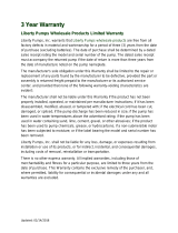
Fig. 5 – Direct Wiring of 115V or 208-230V,
Single Phase, Automatic Pumps
TEMPORARY
MANUAL
OPERATION
DO!
DON’T!
Fig. 4 Piggyback plug installation.
All LE-Series "A" models (automatic pumps) come factory-
equipped with a float switch mounted to the pump. These
models come with two cords - one to the float switch and the
other to the pump motor. The switch cord has a series
(piggyback) plug enabling the pump (motor) cord to be
plugged into the back of it (see Fig. 4). The purpose of this
design is to allow manual operation of the pump.
Prior to pump installation ensure that the mounting bracket
bolt is tight.
For automatic operation using Liberty's supplied switch, the two cords should be interconnected and plugged into a separately fused,
grounded outlet of proper amp capacity for your selected pump model. (See Section 1, General Information, or the pump nameplate for
electrical specifications of your model.) Both cords are equipped with 3-prong plugs and must be plugged into a properly grounded 3-
wire receptacle. DO NOT REMOVE THE GROUND PRONGS.
For manual operation, or in the event of switch failure, the pump cord can be separated and plugged into the electrical outlet, directly
bypassing the switch. 208-230V single phase pumps should only be operated without the float switch by using the circuit breaker or
panel disconnect. Do not let the pump run dry for extended periods.
The turn-on level of LE-Series "A" models is approximately 12" to 16" above the bottom of the basin. The turn-off level is approximately
6" above the bottom of the basin. Other pumping differentials may be obtained by tethering the switch cord to the discharge pipe.
NOTE: With wide angle floats, a minimum cord length of 3.5" from the tether point to the top surface of the float is required for proper
switch operation. If using a differential other than the factory setting, be sure when the pump shuts off at least 6" of fluid is left in the
basin so the impeller remains submerged.
NOTE: If the factory-mounted float is removed from the pump for relocation to the discharge pipe, be sure to replace and properly
tighten the mounting bracket bolt in the pump as it is also used to secure the volute.
LE-Series pump models with an "M" designation are manual models with no switch. They are intended to be run using an approved
liquid level control or approved motor control with correct rating that matches motor input in full load amperes. 3-phase models require
the use of an approved motor control that matches motor input in full load amperes with overload element(s) selected or adjusted in
accordance with control instructions.
Automatic operation with optional control devices: If the pump(s) are to be operated by either a simplex or duplex control panel, or
other optional control device, follow the installation instructions provided with your specific control and make the power connections per
those instructions. If necessary, certain models may be run without a separate control. 208-230V single-phase pumps should only be
operated without the float switch by using the circuit breaker or panel disconnect. Do not let the pump run dry for extended periods.
LE-Series "A" and "M" models: If the pump is to be wired directly into a control device or junction box, and it is necessary to remove
the plugs, have a certified electrician do the wiring in accordance with the National Electric Code and applicable local codes. See Fig. 5
for direct wire installation of single phase, automatic pumps.
In 208-230V installations, one side on
the line going to the pump is always
“hot”, whether the float switch is on or
off. To avoid hazards, install a double
pole disconnect near the pump
installation.
Figure C – Direct wiring of 115V or 208-230V, single
phase, automatic pumps.
©Copyright 2015 Liberty Pumps Inc. All rights reserved 8
Risk of electric shock. Always disconnect the pump from the power source before handling or making
adjustments.
Problem
Cause
Correction
Pump will not run.
Blown fuse or other interruption of
power; improper voltage.
Check that the unit is securely plugged in.
Have an electrician check all wiring for proper
connections and adequate voltage and
capacity.
Switch is unable to move to the
“turn on” position due to
interference with the side of basin
or other obstruction
Position the pump or switch so that it has
adequate clearance for free operation.
Insufficient liquid level.
Make sure the liquid level is allowed to rise
enough to activate switch(s).
Defective switch.
Remove and replace switch.
Pump will not turn
off.
Switch(s) unable to move to the
“turn off” position due to
interference with the side of basin
or other obstacle.
Position the pump or switch so that it has
adequate clearance for free operation.
Defective switch.
Remove and replace switch.
Pump runs or hums,
but does not pump.
Discharge is blocked or restricted.
Check the discharge line for foreign material,
including ice if the discharge line passes
through or into cold areas.
Check valve is stuck closed or
installed backwards.
Remove check valve(s) and examine for
freedom of operation and proper installation.
Gate or ball valve is closed.
Open gate or ball valve.
Total lift is beyond pump's
capability.
Try to route piping to a lower level. If not
possible, a larger pump may be required.
Consult the factory.
Pump impeller is jammed or volute
casing is plugged.
Remove the pump from the basin. Detach the
pump base and clean the area around the
impeller. Reassemble and reinstall.
Pump runs
periodically when
fixtures are not in
use.
Check valve was not installed, is
stuck open or is leaking.
Remove check valve(s) and examine for
freedom of operation and proper installation.
Fixtures are leaking.
Repair fixtures as required to eliminate leakage.
Pump operates
noisily.
Foreign objects in the impeller
cavity.
Remove the pump from the basin. Detach the
pump base and clean the area around the
impeller. Reassemble and reinstall.
Broken impeller.
Consult the factory for information regarding
replacement of impeller.
Worn bearings.
Return pump to the factory or authorized repair
station for repair.
Piping attachments to building are
too rigid.
Replace a portion of the discharge line with
rubber hose or connector.
5. Maintenance and Troubleshooting
©Copyright 2015 Liberty Pumps Inc. All rights reserved 9
NOTE: Liberty Pumps, Inc. assumes no responsibility for damage or injury due to disassembly in the field. Disassembly,
other than at Liberty Pumps or its authorized service centers, automatically voids warranty.
Liberty Pumps, Inc. warrants that pumps of its manufacture are free from all factory defects in material and workmanship
for a period of 3 years from the date of purchase. The date of purchase shall be determined by a dated sales receipt
noting the model and serial number of the pump. The dated sales receipt must accompany the returned pump if the date
of return is more than 3 years from the "CODE" (date of manufacture) number noted on the pump nameplate.
The manufacturer's obligation under this Warranty shall be limited to the repair or replacement of any parts found by the
manufacturer to be defective, provided the part or assembly is returned freight prepaid to the manufacturer or its
authorized service center, and provided that none of the following warranty-voiding characteristics are evident.
The manufacturer shall not be liable under this Warranty if the product has not been properly installed; if it has been
disassembled, modified, abused or tampered with; if the electrical cord has been cut, damaged or spliced; if the pump
discharge has been reduced in size; if the pump has been used in water temperatures above the advertised rating, or
water containing sand, lime, cement, gravel or other abrasives; if the product has been used to pump chemicals or
hydrocarbons; if a non-submersible motor has been subjected to excessive moisture; or if the label bearing the serial,
model and code number has been removed. Liberty Pumps, Inc. shall not be liable for any loss, damage or expenses
resulting from installation or use of its products, or for consequential damages, including costs of removal, reinstallation or
transportation.
There is no other express warranty. All implied warranties, including those of merchantability and fitness for a particular
purpose, are limited to three years from the date of purchase.
This Warranty contains the exclusive remedy of the purchaser, and, where permitted, liability for consequential or
incidental damages under any and all warranties are excluded.
7000 Apple Tree Avenue
Bergen, NY 14416
Phone: (800) 543-2550
Fax: (585) 494-1839
www.libertypumps.com
6. 3 Year Limited Warranty
©Copyright 2015 Liberty Pumps Inc. All rights reserved 10
This page intentionally left blank
  • Page 1 1
  • Page 2 2
  • Page 3 3
  • Page 4 4
  • Page 5 5
  • Page 6 6
  • Page 7 7
  • Page 8 8
  • Page 9 9
  • Page 10 10
  • Page 11 11
  • Page 12 12
  • Page 13 13
  • Page 14 14
  • Page 15 15
  • Page 16 16
  • Page 17 17
  • Page 18 18
  • Page 19 19
  • Page 20 20
  • Page 21 21
  • Page 22 22
  • Page 23 23
  • Page 24 24
  • Page 25 25
  • Page 26 26
  • Page 27 27
  • Page 28 28

Liberty Pumps LEH102A2 Installation guide

Type
Installation guide

Ask a question and I''ll find the answer in the document

Finding information in a document is now easier with AI