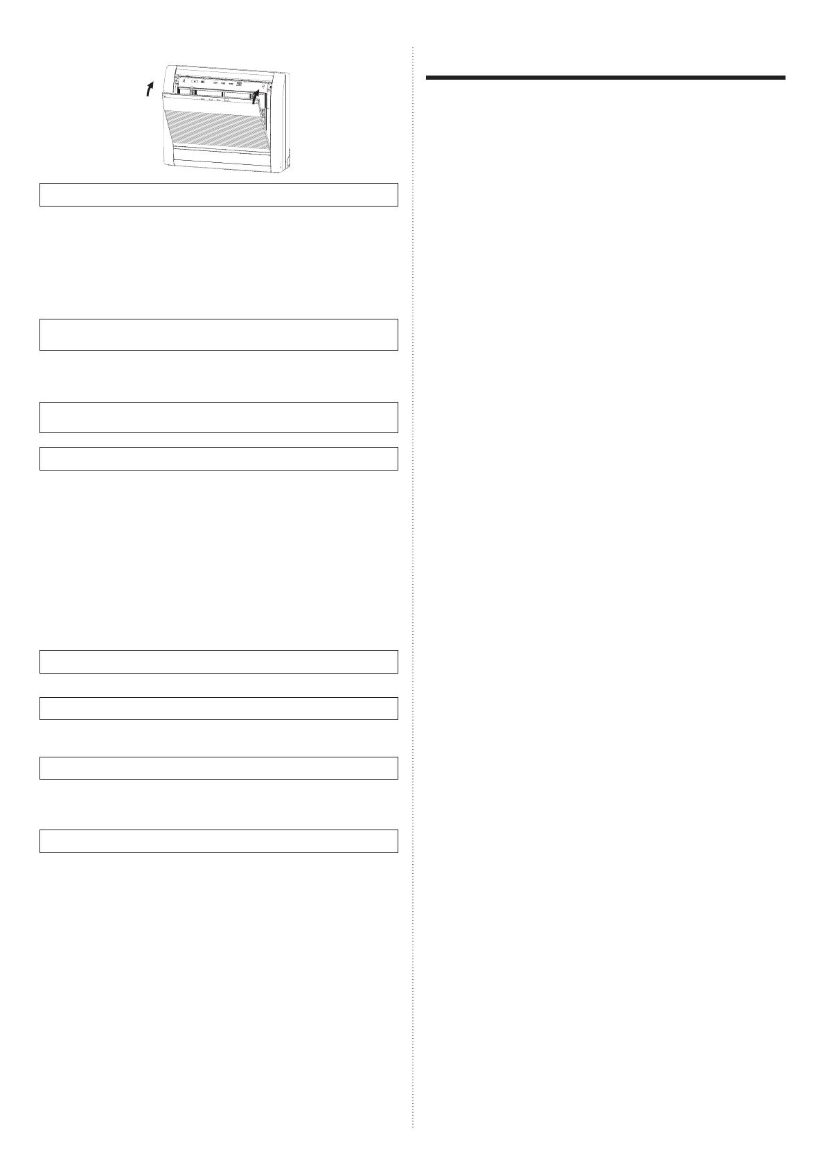
AirStage AGHA004GCAH Operating instructions

Category
Fireplaces
Type
Operating instructions
PART No. 9382567019-02
EnglishDeutschFrançaisEspañolItalianoΕλληνικάPortuguêsРусскийTürkçe
OPERATING MANUAL
INDOOR UNIT (Floor type)
Keep this manual for future reference.
MODE D’EMPLOI
UNITÉ INTÉRIEURE (Type sol)
Conservez ce manuel pour pour toute référence ultérieure.
MANUAL DE FUNCIONAMIENTO
UNIDAD INTERIOR (Tipo suelo)
Conserve este manual para posibles consultas futuras.
MANUAL DE FUNCIONAMENTO
UNIDADE INTERIOR (Tipo de chão)
Guarde este manual para consulta futura.
BEDIENUNGSANLEITUNG
INNENGERÄT (Fbodentyp)
Bewahren Sie dieses Handbuch für eine spätere Bezugnahme auf.
MANUALE DI ISTRUZIONI
UNITÀ INTERNA (Tipo da pavimento)
Conservare questo manuale per consultazione futura.
ΕΓΧΕΙΡΙΔΙΟ ΛΕΙΤΟΥΡΓΙΑΣ
ΕΣΩΤΕΡΙΚΗ ΜΟΝΑΔΑ (Τύπος δαπέδου)
Διατηρήστε το παρόν εγχειρίδιο για μελλοντική αναφορά.
РУКОВОДСТВО ПО ЭКСПЛУАТАЦИИ
ВНУТРЕННИЙ МОДУЛЬ (Напольный тип)
Сохраните данное руководство для последующего использования.
KULLANIM KILAVUZU
İÇ ÜNİTE (Yer tipi)
Bu kılavuzu ileride başvurmak üzere saklayın.
[Original instructions]
Refer to the rating label with the serial number.
MADE IN P.R.C.
EEV internal model
AGYA004GCAH/AGHA004GCAH
AGYA007GCAH/AGHA007GCAH
AGYA009GCAH/AGHA009GCAH
AGYA012GCAH/AGHA012GCAH
AGYA014GCAH/AGHA014GCAH
EEV external model
AGYE004GCAH/AGHE004GCAH
AGYE007GCAH/AGHE007GCAH
AGYE009GCAH/AGHE009GCAH
AGYE012GCAH/AGHE012GCAH
AGYE014GCAH/AGHE014GCAH
En-1
Do not operate the air conditioner with wet hands.
Check the condition of the installation stand for damage.
Operate only with air lters installed.
Do not drink the water drained from the air conditioner.
Do not apply any heavy pressure to radiator ns.
Do not use in ammable gases near the air conditioner.
Do not touch the piping during operation.
Ensure that any electronic equipment is at least 1 m away from either
the indoor or outdoor units.
This appliance is not intended for use by persons (including children)
with reduced physical, sensory or mental capabilities, or lack of ex-
perience and knowledge, unless they have been given supervision or
instruction concerning use of the appliance by a person responsible for
their safety. Children should be supervised to ensure that they do not
play with the appliance.
Note:
Switching the operating mode in the heat recovery system may require
some time to prepare for operation. Please note that this is not a fault.
PRECAUTIONS ON INSTALLATION
CAUTION
Do not attempt to install this air conditioner by yourself.
This unit contains no user-serviceable parts.
Always consult authorized service personnel for repairs.
When moving, consult authorized service personnel for disconnection
and installation of the unit.
The unit must be grounded.
Make sure drain work is implemented properly for drainage.
Avoid installing the air conditioner near a replace or other heating
apparatus.
When installing the indoor and outdoor unit, take precautions to pre-
vent access to infants.
NAME OF PARTS
(5)
(14)
(17)
(13) (11) (10)
(9)
(12)
(6) (7) (8)
(3)
(2)
(1) (4)
(16)
(15)
(1) Operating control panel
(2) Air outlet selection switch
(3) MANUAL AUTO button: This is used to operate it while remote
controller is not available.
(4) Indicator lamps
(5) TIMER Indicator Lamp (orange): It lights on while timer is working.
(6) OPERATION Indicator Lamp (green): It lights on while operating.
(7) FILTER Indicator Lamp (red): It lights on if the lter became dirty.
Clean the lter referring to "CLEANING AND CARE". It lights off
when RESET button is pressed after cleaning.
(8) Remote Control Signal Receiver: This is the place to receive the
signals from the remote controller.
SAFETY PRECAUTIONS
Before using the appliance, read these “PRECAUTIONS” thoroughly
and operate in the correct way.
The instructions in this section all relate to safety; be sure to maintain
save operating conditions.
“WARNING” and “CAUTION” have the following meanings in these
instructions:
WARNING
This mark indicates procedures which, if im-
properly performed, might lead to the death or
serious injury of the user.
CAUTION
This mark indicates procedures which, if im-
properly performed, might possibly result in per-
sonal harm to the user, or damage to property.
PRECAUTIONS ON USE
WARNING
Do not keep exposing oneself to the direct wind of air conditioner for a
long time.
Do not insert ngers or objects into the outlet port or intake grilles.
Except for EMERGENCY, never turn off main as well as sub breaker
of the indoor units during operation. It will cause compressor failure as
well as water leakage.
First, stop the indoor unit by operating the control unit, converter or
external input device and then cut the breaker.
Make sure to operate through the control unit, converter or external
input device.
If the power supply cord of this appliance is damaged, it should only
be replaced by the authorized service personal, since special purpose
tools and speci ed cord are required.
If any refrigerant happens to leak, extinguish any ames, ventilate the
room and get in touch with authorized service personnel.
CAUTION
Provide occasional ventilation during use.
Do not use in applications involving the storage of foods, precision
equipment, or art works.
Do not place animals or plants in the direct path of the air ow.
Do not direct air ow at replaces or heating apparatus.
Do not block or cover the inlet port and outlet port.
Do not climb on, or place objects on, the air conditioner.
Do not set ower vases or water containers on top of air conditioners.
Do not hang objects from the indoor unit.
Do not place anything below the indoor unit that should not get wet.
Always turn off the electrical breaker whenever cleaning the air condi-
tioner or the air lter.
Do not pour water or cleaning solvent on the unit directly, or wash the unit with them.
Do not expose the air conditioner directly to water.
OPERATING MANUAL
PART NO. 9382567019-02
VRF system indoor unit (Floor type)
CONTENTS
SAFETY PRECAUTIONS ....................................................................... 1
NAME OF PARTS .................................................................................. 1
MANUAL AUTO OPERATION ............................................................... 2
AIRFLOW DIRECTION .......................................................................... 2
AIR OUTLET SELECTION ..................................................................... 2
OPERATING TIPS ................................................................................. 3
CLEANING AND CARE.......................................................................... 3
TROUBLESHOOTING ........................................................................... 5
SPECIFICATIONS .................................................................................. 6
En-2
(9) Intake grille
(10) Front panel
(11) Air lter
(12) Vertical air ow direction louver
(13) Horizontal air ow direction louver (behind Air ow Direction Louver
and Damper)
(14) Damper
(15) Air cleaning lter
(16) Rope
(17) Drain Hose
Control unit (optional)
Types of remote controllers:
Wireless remote controller
Wired remote controller
Simple remote controller
For operation method, please refer to the Operating Manual of each
device.
MANUAL AUTO OPERATION
Use the MANUAL AUTO operation in the event the remote control unit is
lost or otherwise unavailable.
CAUTION
Do not press the MANUAL AUTO button with wet hands or pointed ob-
jects, otherwise an electric shock or malfunction may occur.
Starting Operation
Press the MANUAL AUTO button on the operating
control panel.
The operation can be set in the following setting.
Operating mode AUTO:
When Auto mode cannot be selected, it will
operate in the same mode as the other indoor
unit in the same system. (When other indoor
unit in the same system doesn’t operate, the air
conditioner will operate in cooling.)
Fan speed AUTO
Setting temperature 23 °C
Stopping Operation
Press the MANUAL AUTO button on the operating
control panel.
AIRFLOW DIRECTION
Vertical air ow direction
The vertical wind direction can
be controlled with the remote
controller.
1
2
3
4
Cooling, Dry
and Heating
Horizontal air ow direction
The horizontal air ow direction can be manually set by adjusting horizon-
tal air ow direction louvers.
CAUTION
Always adjust the horizontal air ow direction louvers when the damper
is open. Opening the damper forcibly with hands can cause damper to
malfunction.
AIR OUTLET SELECTION
With this function , air come out simultaneously from the upper and lower
air outlets so that the room can be cooled or heated effectively. This
function is set using the switch behind the front grille of the Indoor unit.
(This function is available in cooling and heating operation.)
How to set the out air outlet
Upper air outlet only Upper and lower air outlets
Set the air outlet
selection switch to
Set the air outlet
selection switch to
Air blows out automatically from
the upper and lower air outlets as
shown in the table below.
NOTES:
Set the air outlet selection switch to the end. Otherwise, air outlet cannot
be selected as intended.
Description of operation
(When set to the upper and lower air outlets)
Cooling mode Dry mode Heating mode
Upper and
lower air ow
Upper air ow Upper air ow
only
Upper and
lower air ow
Upper air ow
Room temper-
ature and set
temperature
are different.
Room tem-
perature is
close to set
temperature,
or the air
conditioner has
operated for 1
hour.
Air ow
temperature is
high.
Air ow tem-
perature is low.
(During
defrosting
operation, start
of operation,
etc.)
En-3
If the air conditioner is operated under higher temperature conditions
than those listed, the built-in protection circuit may operate to prevent
internal circuit damage. Also, during Cooling and Dry modes, if the unit
is used under conditions of lower temperature than those listed above,
the heat-exchanger may freeze, leading to water leakage and other
damage.
If the unit is used for long periods under high-humidity conditions,
condensation may form on the surface of the indoor unit, and drip onto
the oor or other objects underneath.
Do not use this unit for any purposes other than the Cooling, Heating,
Dehumidifying, and air-circulation of rooms in ordinary dwellings.
CLEANING AND CARE
CAUTION
Before cleaning the unit, be sure to stop the unit and disconnect the
power supply.
Do not stand on an unstable platform when cleaning.
When removing and replacing the air lters, be sure not to touch the
heat exchanger, as personal injury may result.
Be sure the intake grille is installed securely.
Do not clean the inside of the unit by yourself. To clean the inside,
always consult authorized service personnel.
When cleaning the unit’s body, do not use water hotter than 40 °C,
harsh abrasive cleansers, or volatile agents like benzene or thinner.
If dirt is allowed to accumulate on the air lter, air ow will be reduced,
lowering operating ef ciency and increasing noise.
During periods of normal use, the air lters should be cleaned every 2
weeks.
Cleaning the intake grille
1. Remove the Intake Grille.
(1) Place your ngers at both top indicator of the grille panel, and pull
forward; if the grille seems to catch part way through its movement,
continue pulling down to remove.
(2) Unhook the ropes which holds the grille.
Rope
1
1
2
2
Intake
Grille
2. Clean with water.
Remove dust with a vacuum cleaner; wipe the unit with warm water, then
dry with a clean, soft cloth.
OPERATING TIPS
Operation and Performance
About priority state and standby state
Multiple indoor units can be connected within the same system.
Depending on the system, choice of operating mode are limited.
Cooling priority state:
When the other indoor units within the same system operate in cooling
or dry mode, heating can not be selected at the same time.
Heating priority state:
When the other indoor units within the same system operate in heating
mode, cooling and dry mode can not be selected at the same time.
Standby state:
The standby state activates when 2 or more indoor units start up at the
same time in different mode. Any indoor unit other than priority mode
will wait in standby state until priority mode changes (operation starts
as soon as priority is switched).
At this time, the operation indicator lamp (green) lights up and the timer
indicator lamp (red) ashes.
Low ambient cooling
When the outdoor temperature drops, the outdoor unit’s fans may
switch to Low Speed, or one of the fans may stop intermittently.
Heating performance
Heating mode operates on the heat-pump principle, absorbing heat
from outdoor air and transferring that heat indoors. As a result, the
operating performance is reduced as outdoor air temperature drops.
If you feel that insuf cient heating performance is being produced, we
recommend you use this air conditioner in conjunction with another
type of heating appliance.
Heating mode heat your entire room by recirculating air throughout the
room, with the result that some time may be required after rst starting
the air conditioner until the room is heated.
Microcomputer-controlled automatic defrosting
When using the Heating mode under conditions of low outdoor air
temperature high humidity, frost may form on the outdoor unit, result-
ing in reduced operating performance. In order to prevent this kind of
reduced performance, this unit is equipped with a Microcomputer-con-
trolled automatic defrosting function. If frost forms, the air conditioner
will temporarily stop, and the defrosting circuit will operate brie y (for
about 4 to 15 minutes).
During Automatic Defrosting operation, the OPERATION indicator
lamp (green) will ash.
Oil recovery operation
Periodically, the oil recovery operation is performed in order to return
compressor oil to the outdoor unit.
During oil recovery operation, the OPERATION indicator lamp (green)
will ash (for about 10 minutes).
Temperature and humidity range
The temperature and humidity required for operating this product is as
shown in the following table.
Cooling/Dry Mode Heating Mode
Outdoor
temperature
Please refer to the speci cation of outdoor units.
Indoor
temperature
18 to 32 °C DB 10 to 30 °C DB
Indoor humidity About 80% or less
En-4
3. Replace the Intake Grille.
(1) Hook the ropes.
(2) Set the left and right mounting shafts into the bearings at the bottom
of the panel.
(3) Press the place where the mark on the diagram indicates and close
the intake grille.
Intake
Grille
3
2
1
2
1
3
Rope
Cleaning the Air Filter
1. Open the Intake Grille, and remove the air lter.
Push down the air lter’s handle, disconnect
the 2 upper tabs, and pull out.
2. Remove dust with a vacuum cleaner or by washing.
After washing, allow to dry thoroughly in a shaded place.
3. Replace the Air Filter and close the Intake Grille.
(1) Align the sides of the air lter with the panel, and push in fully, making
sure the 2 upper tabs are returned properly to their holes in the panel.
PANEL
AIR FILTER
PANEL
AIR FILTER
(2) Close the Intake Grille.
Dust can be cleaned from the air lter either with a vacuum cleaner,
or by washing the lter in a solution of mild detergent and warm water.
If you wash the lter, be sure to allow it to dry thoroughly in a shady
place before reinstalling.
If dirt is allowed to accumulate on the air lter, air ow will be reduced,
lowering operating ef ciency and increasing noise.
During periods of normal use, the Air Filters should be cleaned every
two weeks.
When used for extended periods, the unit may accumulate dirt
inside, reducing its performance. We recommend that the unit be
inspected regularly, in addition to your own cleaning and care. For
more information, consult authorized service personnel.
When shutting down the unit for one month or more, rst allow the
fan mode to operate continuously for about one-half day to allow
internal parts to dry thoroughly.
Air cleaning lter installation
1. Open the Intake Grille and remove the Air lters.
2. Install the Air cleaning lter set (set of 2).
Set the air cleaning lter into the panel.
Catch it on 5 places of picks.
(3 places of upper parts and lower part 2 places.)
Air cleaning lter
3. Install the two Air lters and close the Intake Grille.
When air cleaning lters are used, the effect will increased by setting
the fan speed to “High”.
Replacing dirty air cleaning lters
Replace lters with the following components (purchased separately).
APPLE-CATECHIN FILTER: UTR-FC03-2
ION DEODORIZATION FILTER: UTR-FC03-3
1. Open the Intake Grille and remove the Air lters.
2. Replace them by two new Air cleaning lters.
(1) Remove the old air cleaning lters in reverse order of their installation.
(2) Install in the same way as for installation of the air cleaning lter set.
En-5
3. Install the two Air lters and close the Intake Grille.
In regard to the air cleaning lters
APPLE-CATECHIN FILTER (1 sheet)
The lters are disposable lters. (They can not be washed and reused.)
For storage of the lters, use the lters as soon as possible after the
package has been opened.
(The air cleaning effect decreases when the lters are left in the
opened package)
Generally, the lters should be exchanged about every 3 months.
Please buy dedicated APPLE-CATECHIN FILTER (UTR-FC03-2) (Sold
separately) to exchange the used dirty air cleaning lters.
ION DEODORIZATION FILTER (1 sheet) - light blue
The lters should be exchanged about every 3 years so as to maintain
the deodorizing effect.
Please buy dedicated ION DEODORIZATION FILTER (UTR-FA13-2)
(Sold separately) when exchanging the lters.
Maintenance of ION DEODORIZATION FILTER
In order to maintain the deodorizing effect, please clean the lter in the
following way every 3 months.
(1) Remove the lter.
(2) Clean with water and dry in the air.
1) Flush the lters with high-pressure hot water until the surface of
the lters are covered with water. Please ush with diluent neutral
detergent. (Never wash by reaming or rubbing, otherwise it will
damage the deodorizing effect.)
2) Rinse with water ow.
3) Dry in shade.
(3) Reinstall the lter.
Cleaning body
Wash the body with warm water, and then dry with a clean and soft cloth.
When not using for an extended period
Leave the breaker on for at least 12 hours before starting operation when
it is to be used again.
After extended non-use of the unit
If you have shut down the indoor unit for 1 month or more, perform the
FAN operation for half a day to dry the internal parts thoroughly before
you perform normal operation.
Additional inspection
After long period of use, accumulated dust inside the indoor unit may re-
duce the product performance even if you have maintained the unit with
instructed daily care or cleaning procedures written in this manual.
In such a case, a product inspection is recommended.
For more information, consult authorized service personnel.
TROUBLESHOOTING
The following conditions are not breakdowns or op-
eration failures.
Doesn’t operate immediately:
If the unit is stopped and then immediately started again, the com-
pressor will not operate for about 3 minutes, in order to prevent fuse
blowouts.
Whenever the electrical breaker is turned off then on again, the protec-
tion circuit will operate for about 3 minutes, preventing unit operation
during that period.
Air ow is weak or stops:
When Heating operation is started, indoor unit’s fan may temporarily
stop, to allow internal parts to warm up.
During Heating operation, if the room temperature rises above the
thermostat setting, the outdoor unit will stop, and the indoor unit’s fan
will stop. If you wish to warm the room further, set the thermostat for a
higher setting.
During oil recovery operation, the air ow may stop for approximately
10 minutes. (See page 3)
During Heating operation, the unit will temporarily stop operation (be-
tween 4 and 15 minutes) as the Automatic Defrosting mode operates.
(See page 3)
The fan may operate at low speed during Dry operation or when the
unit is monitoring the room’s temperature.
In the monitor AUTO operation, the fan will operate at low speed.
Flashing lamps:
The OPERATION indicator lamp (green) ashes:
An oil recovery operation is being performed. (See page 3)
The OPERATION indicator lamp (green) ashes:
An automatic defrosting operation is being performed. (See page 3)
The OPERATION indicator lamp (green) and TIMER indicator lamp
(orange) are ashing alternately:
It has recovered from a power outage.
The OPERATION indicator lamp (green) and TIMER indicator lamp
(orange) are ashing simultaneously:
It is operating in trial operation mode. Ask a manager as there may be
maintenance being conducted.
The OPERATION indicator lamp (green) lights up and the TIMER
indicator lamp (orange) ashes:
This is the standby state. (See page 3)
Noise is heard:
In the following conditions there are sounds of water owing from the
indoor unit and the operation sound becomes loud. These are the
sounds of the owing of refrigerant.
When operation starts
When oil recovery operation nishes
When automatic defrosting operation nishes
During operation, a slight squeaking sound may be heard. This is the
result of minute expansion and contraction of the panel due to tem-
perature changes.
During Heating operation, a sizzling sound may be heard occasionally.
This sound is produced by the Automatic Defrosting operation. (See
page 3)
Smells:
Some smell may be emitted from the indoor unit. This smell is the
result of room smells (furniture, tobacco, etc.) which have been taken
into the air conditioner.
Fog comes out of the indoor unit:
During Cooling operation, a thin mist may be seen emitted from the
indoor unit. This results from the sudden Cooling of room air by the air
emitted from the air conditioner, resulting in condensation and misting.
Steam comes out of the indoor unit:
During Heating operation, the outdoor unit’s fan may stop, and steam
may be seen rising from the unit. This is due to the Automatic Defrost-
ing operation. (See page 3)
Water is produced from the outdoor unit:
During Heating operation, water may be produced from the outdoor
unit due to the Automatic Defrosting operation.
En-6
The following conditions may not be breakdowns so
check again.
Doesn’t operate at all:
Has there been a power failure?
Has a fuse blown out, or a circuit breaker been tripped?
Is the main power switch set to the OFF position?
Are you trying to engage in an operation different from the priority
state? (See page 3)
Is it in standby state? (See page 3)
The operation mode cannot be changed:
Are you trying to change to an operation different from the priority
conditions? (See page 3)
Poor Cooling (or Heating) performance:
Did you adjust the room temperature settings (thermostat) correctly?
Is the air lter dirty? (See page 3)
Are the air conditioner’s inlet port or outlet port blocked?
Is there a window or door open?
In the case of Cooling operation, is a window allowing bright sunlight to
enter? (Close the curtains.)
In the case of Cooling operation, are there heating apparatus and com-
puters inside the room, or are there too many people in the room?
Is the fan speed set to low?
Set the temperature lower than the room temperature and use it:
Temperature does not fall down well.
Temperature may not fall down depending on the room conditions.
(While high humidity or the room temperature is high.) (See page 3)
In following situations stop operation immediately and
get in touch with authorized service personnel.
The problem cannot be solved even when the troubleshooting checks
have been performed.
The FILTER indicator lamp (red) is ashing very fast.
The wired remote controller or simple remote controller indicate Er
(when connected).
It has burning smell.
SPECIFICATIONS
MODEL
AG*A004
GCAH
AG*A007
GCAH
AG*A009
GCAH
AG*A012
GCAH
AG*A014
GCAH
POWER SOURCE 220-240V ~ 50Hz, 230V ~ 60Hz
AVAILABLE
VOLTAGE RANGE
198 to 264 V (50Hz)
198 to 253 V (60Hz)
COOLING
CAPACITY
[kW]
1.1 2.2 2.8 3.6 4.0
[Btu/h]
3,800 7,500 9,600 12,300 15,400
HEATING
CAPACITY
[kW]
1.3 2.8 3.2 4.0 4.5
[Btu/h]
4,400 9,600 10,900 14,000 17,100
INPUT
POWER
[W]
12/14 (*1) 16 17 22 29
CURRENT
[A]
0.11/0.13
(*1)
0.14 0.15 0.18 0.23
SOUND PRESSURE LEVEL
HIGH
dB [A]
35/36 (*1) 37 38 42 46
MED - HIGH
dB [A]
33 35 36 39 42
MED
dB [A]
31 33 34 37 39
MED - LOW
dB [A]
30 31 31 35 36
LOW
dB [A]
28 29 29 33 33
QUIET
dB [A]
22 22 22 30 30
DIMENSIONS & WEIGHT
HEIGHT [mm] 600
WIDTH [mm] 740
DEPTH [mm] 200
WEIGHT [kg] 15
*1: This value is “cooling operation/heating operation”.
MODEL
AG*E004
GCAH
AG*E007
GCAH
AG*E009
GCAH
AG*E012
GCAH
AG*E014
GCAH
POWER SOURCE 220-240V ~ 50Hz, 230V ~ 60Hz
AVAILABLE
VOLTAGE RANGE
198 to 264 V (50Hz)
198 to 253 V (60Hz)
COOLING
CAPACITY
[kW] 1.1 2.2 2.8 3.6 4.0
[Btu/h]
3,800 7,500 9,600 12,300 15,400
HEATING
CAPACITY
[kW] 1.3 2.8 3.2 4.0 4.5
[Btu/h]
4,400 9,600 10,900 14,000 17,100
INPUT
POWER
[W] 12/14 (*1) 16 17 22 29
CURRENT [A]
0.11/0.13
(*1)
0.14 0.15 0.18 0.23
SOUND PRESSURE LEVEL
HIGH
dB [A]
35/36 (*1) 37 38 42 46
MED - HIGH
dB [A]
33 35 36 39 42
MED
dB [A]
31 33 34 37 39
MED - LOW
dB [A]
30 31 31 35 36
LOW
dB [A]
28 29 29 33 33
QUIET
dB [A]
22 22 22 30 30
DIMENSIONS & WEIGHT
HEIGHT [mm] 600
WIDTH [mm] 740
DEPTH [mm] 200
WEIGHT [kg] 14.5
*1: This value is “cooling operation/heating operation”.
Acoustic Noise Information:
The maximum sound pressure level is less than 70 dB (A) for both
indoor unit and outdoor unit. According IEC 704-1 and ISO 3744.
This product contains uorinated greenhouse gases.
  • Page 1 1
  • Page 2 2
  • Page 3 3
  • Page 4 4
  • Page 5 5
  • Page 6 6
  • Page 7 7
  • Page 8 8

AirStage AGHA004GCAH Operating instructions

Category
Fireplaces
Type
Operating instructions

Ask a question and I''ll find the answer in the document

Finding information in a document is now easier with AI