Fujitsu AUXS024GLEH Operating instructions

Type
Operating instructions

This manual is also suitable for

PART No. 9383490019
[Original instructions]
BEDIENUNGSANLEITUNG
INNENGERÄT (3D Fluss-Kassettentyp)
Bewahren Sie dieses Handbuch für eine spätere Bezugnahme auf.
OPERATING MANUAL
INDOOR UNIT
(3D ow cassette type)
Keep this manual for future reference.
MANUAL DE FUNCIONAMIENTO
UNIDAD INTERIOR (Tipo casete de ujo 3D)
Conserve este manual para posibles consultas futuras.
MANUALE DI ISTRUZIONI
UNITÀ INTERNA (Tipo a cassetta con usso 3D)
Conservare questo manuale per consultazione futura.
ΕΓΧΕΙΡΙΔΙΟ ΛΕΙΤΟΥΡΓΙΑΣ
ΕΣΩΤΕΡΙΚΗ ΜΟΝΑΔΑ (τύπος κασέτας με ροή 3D)
Διατηρήστε το παρόν εγχειρίδιο για μελλοντική αναφορά.
MANUAL DE FUNCIONAMENTO
UNIDADE INTERIOR (tipo de cassete de uxo 3D)
Guarde este manual para consulta futura.
РУКОВОДСТВО ПО ЭКСПЛУАТАЦИИ
ВНУТРЕННИЙ МОДУЛЬ (кассетный тип с 3D потоком)
Сохраните данное руководство для последующего использования.
KULLANIM KILAVUZU
İÇ ÜNİTE (3D akış kaset tipi)
Bu kılavuzu ileride başvurmak üzere saklayın.
MODE D’EMPLOI
UNITÉ INTÉRIEURE (Type cassette à ux 3D)
Conservez ce manuel pour pour toute référence ultérieure.
Deutsch EnglishEspañolItalianoΕλληνικάPortuguêsРусскийTürkçe Français
Refer to the rating label with the serial number.
MADE IN P.R.C.
AUXS018GLEH
AUXS024GLEH
9383490019_OM.indb 1 05/02/2019 18:24:37
En-1
SAFETY PRECAUTIONS
Before using the appliance, read these “PRECAUTIONS” thoroughly
and operate in the correct way.
The instructions in this section all relate to safety; be sure to maintain
safe operating conditions.
“WARNING” and “CAUTION” have the following meanings in these
instructions:
WARNING
This mark indicates procedures which, if im-
properly performed, might lead to the death or
serious injury of the user.
CAUTION
This mark indicates procedures which, if im-
properly performed, might possibly result in per-
sonal harm to the user, or damage to property.
PRECAUTIONS ON USE
WARNING
● Do not keep exposing oneself to the direct wind of air conditioner for a
long time.
● Do not insert ngers or objects into the outlet port or intake grille.
● Except for EMERGENCY, never turn off main as well as sub breaker
of the indoor units during operation. It will cause compressor failure as
well as water leakage. First, stop the indoor unit by operating the con-
trol unit, converter or external input device and then cut the breaker.
Make sure to operate through the control unit, converter or external
input device.
If the power supply cord of this appliance is damaged, it should only
be replaced by the authorized service personal, since special purpose
tools and specied cord are required.
● If any refrigerant happens to leak, extinguish any ames, ventilate the
room and get in touch with authorized service personnel.
CAUTION
● Do not place animals or plants in the direct path of the airow.
● Do not direct airow at replaces or heating apparatus.
● Do not block or cover the inlet port and outlet port.
● Do not climb on, or place objects on, the air conditioner.
● Do not set ower vases or water containers on top of air conditioners.
● Do not hang objects from the indoor unit.
Do not place any other electronic appliance or furniture. Otherwise,
water drop from the product may cause damage or failure of the appli-
ance or furniture.
● Always turn off the electrical breaker whenever cleaning the air condi-
tioner or the air lter.
Do not pour water or cleaning solvent on the unit directly, or wash the
unit with them.
● Do not expose the air conditioner directly to water.
Do not operate the air conditioner with wet hands.
● Check the condition of the installation stand for damage.
● Operate only with air lters installed.
● Do not drink the water drained from the air conditioner.
● Do not apply any heavy pressure to radiator ns.
● Do not use inammable gases near the air conditioner.
Do not touch the piping during operation.
Ensure that any electronic equipment is at least 1 m away from either
the indoor or outdoor units.
This appliance is not intended for use by persons (including children)
with reduced physical, sensory or mental capabilities, or lack of ex-
perience and knowledge, unless they have been given supervision or
instruction concerning use of the appliance by a person responsible for
their safety. Children should be supervised to ensure that they do not
play with the appliance.
If the unit is not used for more than a month, perform a ventilation
operation before preforming a regular operation in order to dry the
internal components.
Note:
Switching the operating mode in the heat recovery system may require
some time to prepare for operation. Please note that this is not a fault.
PRECAUTIONS ON INSTALLATION
CAUTION
Do not attempt to install this air conditioner by yourself.
This unit contains no user-serviceable parts. Always consult authorized
service personnel for repairs.
When moving, consult authorized service personnel for disconnection
and installation of the unit.
The unit must be grounded.
● Make sure drain work is implemented properly for drainage.
● Avoid installing the air conditioner near a replace or other heating
apparatus.
● When installing the indoor and outdoor units, take precautions to pre-
vent access by infants.
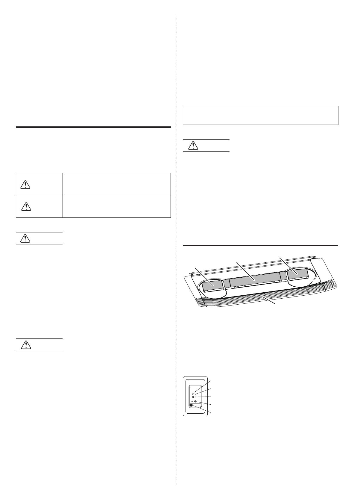
NAME OF PARTS
(1)
(2)-1
(2)-2
(2)-3
(1) Air lter (in air intake grille)
(2) Airow direction aps
The name of the outlet ports (in “Individual Horizontal Hold setting” by
the wired remote controller). Please refer to the “AIRFLOW DIREC-
TION”.
(2)-1: Outlet 1 (Center fan)
(2)-2: Outlet 2 (Side fan)
(2)-3: Outlet 3 (Side fan)
(3) IR Receiver (optional)
(4)
(3)
(5)
(6)
(7)
(8)
(4) OPERATION Indicator Lamp (Green): It lights on
while operating.
(5) TIMER Indicator Lamp (Orange): It lights on while
timer is working.
(6) FILTER Indicator Lamp (Red): Lights on when it
is time to clean the lter. Clean the lter according
to “CLEANING AND CARE”. Once the cleaning is
completed, turn off the indicator lamp by operating
the Filter sign reset function on the remote control-
ler.
(7) Manual auto button: It is used to operate it while
remote controller is not available.
(8) Remote control signal receiver: It is the place to
receive the signals from the remote controller.
CONTENTS
SAFETY PRECAUTIONS ........................................................................ 1
NAME OF PARTS ................................................................................... 1
MANUAL AUTO OPERATION ................................................................ 2
COMFORT AIRFLOW ............................................................................. 2
AIRFLOW DIRECTION ........................................................................... 2
OPERATING TIPS .................................................................................. 3
CLEANING AND CARE........................................................................... 4
TROUBLESHOOTING ............................................................................ 5
SPECIFICATIONS ................................................................................... 6
OPERATING MANUAL
PART No. 9383490019
VRF system indoor unit (3D ow cassette type)
9383490019_OM.indb 1 05/02/2019 18:24:37
En-2
Control unit (optional)
Types of remote controllers:
● Wireless remote controller
● Wired remote controller
● Simple remote controller
For operation method, please refer to the operating manual of each
device.
MANUAL AUTO OPERATION
Use the MANUAL AUTO operation in the event the wireless remote
controller is lost or otherwise unavailable.
*Limited to only when IR Receiver is installed.
CAUTION
Do not press the MANUAL AUTO button with wet hands or pointed ob-
jects, otherwise an electric shock or malfunction may occur.
Starting Operation
Press the MANUAL AUTO button on the IR Receiver.
The operation can be set in the following setting.
Operating mode AUTO:
When Auto mode cannot be selected, it will
operate in the same mode as the other indoor
unit in the same system. (When other indoor
unit in the same system doesn’t operate, the air
conditioner will operate in cooling.)
Fan speed AUTO
Setting temperature 23 °C
Stopping Operation
Press the MANUAL AUTO button on the IR Receiver.
COMFORT AIRFLOW
Airow direction (vertical/horizontal) is set to provide air conditioning for
the entire room.
It is recommended to use this setting.
While the Comfort airow has been set, the airow direction is xed and
cannot be set manually.
To use this setting, the specic wired remote controller is required. For
details, consult authorized service personnel.
For setting procedure, please refer to the operating manual of the remote
controller.
AIRFLOW DIRECTION
The vertical and horizontal airow direction can be controlled with the
remote controller.
Horizontal airow direction
The horizontal airow direction can be controlled with the remote control-
ler.
(1)
(2)
(3)
(4)
(5)
Individual HT Hold
Each airow direction can be set individually using the remote controller.
To use this setting, the specic wired remote controller is required. For
details, consult authorized service personnel.
For setting procedure, please refer to the operating manual of the remote
controller.
9383490019_OM.indb 2 05/02/2019 18:24:38
En-3
Low ambient cooling
When the outdoor temperature drops, the outdoor unit’s fans may
switch to Low Speed, or one of the fans may stop intermittently.
Heating performance
Heating mode operates on the heat-pump principle, absorbing heat
from outdoor air and transferring that heat indoors. As a result, the
operating performance is reduced as outdoor air temperature drops.
If you feel that insufcient heating performance is being produced, we
recommend you use this air conditioner in conjunction with another
type of heating appliance.
Heating mode heat your entire room by recirculating air throughout the
room, with the result that some time may be required after rst starting
the air conditioner until the room is heated.
Microcomputer-controlled automatic defrosting
When using the Heating mode under conditions of low outdoor air
temperature high humidity, frost may form on the outdoor unit, result-
ing in reduced operating performance. In order to prevent this kind of
reduced performance, this unit is equipped with a Microcomputer-con-
trolled automatic defrosting function. If frost forms, the air conditioner
will temporarily stop, and the defrosting circuit will operate briey (for
about 4 to 15 minutes).
During Automatic Defrosting operation, the OPERATION indicator
lamp (green) will ash (When IR Receiver is installed).
Oil recovery operation
Periodically, the oil recovery operation is performed in order to return
compressor oil to the outdoor unit. During oil recovery operation, the
OPERATION indicator lamp (green) will ash for about 10 minutes
(When IR Receiver is installed).
Temperature and humidity range
The temperature and humidity required for operating this product is as
shown in the following table.
Cooling/Dry Mode Heating Mode
Outdoor
temperature
Please refer to the specication of outdoor units.
Indoor
temperature
18 to 32 °C DB 10 to 30 °C DB
Indoor humidity About 80% or less
If the air conditioner is operated under higher temperature conditions
than those listed, the built-in protection circuit may operate to prevent
internal circuit damage. Also, during Cooling and Dry modes, if the unit
is used under conditions of lower temperature than those listed above,
the heat-exchanger may freeze, leading to water leakage and other
damage.
If the unit is used for long periods under high-humidity conditions,
condensation may form on the surface of the indoor unit, and drip onto
the oor or other objects underneath.
Do not use this unit for any purposes other than the Cooling, Heating,
Dehumidifying, and air-circulation of rooms in ordinary dwellings.
Vertical airow direction
The vertical airow direction can be controlled with the remote controller.
Swing
The swinging vertical airow direction can be set.
OPERATING TIPS
Operation and Performance
About priority state and standby state
Multiple indoor units can be connected within the same system. De-
pending on the system, choice of operating mode are limited.
Cooling priority state:
When the other indoor units within the same system operate in cooling
or dry mode, heating cannot be selected at the same time.
Heating priority state:
When the other indoor units within the same system operate in heating
mode, cooling and dry mode cannot be selected at the same time.
Standby state:
The standby state activates when 2 or more indoor units start up at the
same time in different mode. Any indoor unit other than priority mode
will wait in standby state until priority mode changes (operation starts
as soon as priority is switched).
At this time, the OPERATION indicator lamp (green) lights up and the
TIMER indicator lamp (orange) ashes (When IR Receiver is installed).
9383490019_OM.indb 3 05/02/2019 18:24:39
En-4
CLEANING AND CARE
CAUTION
Before cleaning the unit, be sure to stop the unit and disconnect the
power supply.
Do not stand on an unstable platform when cleaning.
● When removing and replacing the air lters, be sure not to touch the
heat exchanger, as personal injury may result.
● Be sure the intake grille is installed securely.
Do not clean the inside of the unit by yourself. To clean the inside,
always consult authorized service personnel.
When cleaning the unit’s body, do not use water hotter than 40 °C,
harsh abrasive cleansers, or volatile agents like benzene or thinner.
● Do not remove any part from the unit except for the lter.
● If dirt is allowed to accumulate on the Air Filter, airow will be reduced,
lowering operating efciency and increasing noise.
● During periods of normal use, the air lters should be cleaned every 2
months.
Cleaning the Air Filter
When the lter indicator is displayed on the IR receiv-
er or the wired remote controller, remove and clean
the lter.
* The diagram shows the rear view seen from the diagonally behind.
1. Remove three hooks to release and hang the in-
take grille.
Hooks
Back
Front
Loosen the screws and remove two hanging wires.
Tap tight screw
2. Hold the handle to lift the air lter.
* The diagram shows the removed intake grille for explanatory purpose.
Handles
Air Filter
Release the hooks
Air Filter
(Side view)
Back
Front
3. Remove three hooks.
Hooks
4. Pull the air lter downward to remove it. Similarly,
remove the other air lter.
5. Clean the air lters.
Remove the dust from the air lters by vacuuming or washing them. After
washing, allow the air lters to dry thoroughly in an area protected from
sunlight.
Dust can be cleaned from the air lter either with a vacuum cleaner,
or by washing the lter in a solution of mild detergent and warm water.
If you wash the lter, be sure to allow it to dry thoroughly in a shady
place before reinstalling.
If dirt is allowed to accumulate on the air lter, airow will be reduced,
lowering operating efciency and increasing noise.
6. Attach two air lters.
First, hold two handles of the air lter to lift it above the inside set.
9383490019_OM.indb 4 05/02/2019 18:24:40
En-5
7. Insert three hooks.
Hooks
8. Hold down the handle and set the hooks.
Handles
Insert the hooks
Air Filter
Air Filter
9. Fix two hanging wires.
Tighten the screws and x the hanging wires.
Tap tight screw
10. Lift the intake grille and insert three hooks.
Hooks
● After turning the power on, press the lter button on the remote control-
ler to turn off the lter indicator. (Refer to the operating manual packed
with remote controller for details.)
Cleaning the body
Wash the body with warm water, and then dry with a clean and soft cloth.
When not using for an extended period
Leave the breaker on for at least 12 hours before starting operation when
it is to be used again.
TROUBLESHOOTING
The following conditions are not breakdowns or op-
eration failures.
Does not operate immediately:
If the unit is stopped and then immediately started again, the com-
pressor will not operate for about 3 minutes, in order to prevent fuse
blowouts.
● Whenever the electrical breaker is turned off then on again, the protec-
tion circuit will operate for about 3 minutes, preventing unit operation
during that period.
Airow is weak or stops:
When Heating operation is started, indoor unit’s fan may temporarily
stop, to allow internal parts to warm up.
During Heating operation, if the room temperature rises above the
thermostat setting, the outdoor unit will stop, and the indoor unit’s fan
will stop. If you wish to warm the room further, set the thermostat for a
higher setting.
● During oil recovery operation, the airow may stop for approximately
10 minutes. (See page 3)
During Heating operation, the unit will temporarily stop operation (be-
tween 4 and 15 minutes) as the Automatic Defrosting mode operates.
(See page 3)
The fan may operate at low speed during Dry operation or when the
unit is monitoring the room’s temperature.
In the monitor AUTO operation, the fan will operate at low speed.
Flashing lamps (When IR Receiver is installed) :
● The OPERATION indicator lamp (green) ashes:
An oil recovery operation is being performed. (See page 3)
● The OPERATION indicator lamp (green) ashes:
An automatic defrosting operation is being per formed. (See page 3)
The OPERATION indicator lamp (green) and TIMER indicator lamp
(orange) are ashing alternately:
It has recovered from a power outage.
The OPERATION indicator lamp (green) and TIMER indicator lamp
(orange) are ashing simultaneously:
It is operating in trial operation mode. Ask a manager as there may be
maintenance being conducted.
The OPERATION indicator lamp (green) lights up and the TIMER
indicator lamp (orange) ashes:
This is the standby state. (See page 3)
Noise is heard:
● In the following conditions there are sounds of water owing from the
indoor unit and the operation sound becomes loud. These are the
sounds of the owing of refrigerant.
When operation starts
When oil recovery operation nishes
When automatic defrosting operation nishes
● During operation, a slight squeaking sound may be heard. This is the
result of minute expansion and contraction of the panel due to tem-
perature changes.
During Heating operation, a sizzling sound may be heard occasionally.
This sound is produced by the Automatic Defrosting operation. (See
page 3)
Smells:
Some smell may be emitted from the indoor unit. This smell is the
result of room smells (furniture, tobacco, etc.) which have been taken
into the air conditioner.
Fog comes out of the indoor unit:
During Cooling operation, a thin mist may be seen emitted from the
indoor unit. This results from the sudden Cooling of room air by the air
emitted from the air conditioner, resulting in condensation and mist-
ing.
Steam comes out of the indoor unit:
During Heating operation, the outdoor unit’s fan may stop, and steam
may be seen rising from the unit. This is due to the Automatic Defrost-
ing operation. (See page 3)
Water is produced from the outdoor unit:
During Heating operation, water may be produced from the outdoor
unit due to the Automatic Defrosting operation.
9383490019_OM.indb 5 05/02/2019 18:24:41
En-6
The following conditions may not be breakdowns so
check again.
Does not operate at all:
Has there been a power failure?
● Has a fuse blown out, or a circuit breaker been tripped?
Is the main power switch set to the OFF position?
Are you trying to engage in an operation different from the priority
state? (See page 3)
Is it in standby state? (See page 3)
The operation mode cannot be changed:
Are you trying to change to an operation different from the priority
conditions? (See page 3)
Poor Cooling (or Heating) performance:
● Did you adjust the room temperature settings (thermostat) correctly?
● Is the air lter dirty? (See page 4)
● Are the air conditioner’s inlet port or outlet port blocked?
Is there a window or door open?
In the case of Cooling operation, is a window allowing bright sunlight to
enter? (Close the curtains.)
In the case of Cooling operation, are there heating apparatus and com-
puters inside the room, or are there too many people in the room?
Is the fan speed set to low?
Temperature does not fall down well.:
Set the temperature lower than the room temperature and use it. Tem-
perature may not fall down depending on the room conditions. (While
high humidity or the room temperature is high.) (See page 3)
In the following situations, stop operation immediately
and get in touch with authorized service personnel.
● The problem cannot be solved even when the troubleshooting checks
have been performed.
● The FILTER indicator lamp (red) is ashing very fast.(When IR Re-
ceiver is installed)
The wired remote controller or simple remote controller indicate Er
(when connected).
It has burning smell.
SPECIFICATIONS
MODEL
AUXS018GLEH AUXS024GLEH
POWER SOURCE 220-240V ~ 50Hz, 230V ~ 60Hz
AVAILABLE VOLTAGE RANGE
198 to 264 V (50Hz) , 198 to 253 V (60Hz)
COOLING
CAPACITY
[kW]
5.6 7.1
[Btu/h] 19,100 24,200
HEATING
CAPACITY
[kW]
6.3 8.0
[Btu/h] 21,500 27,300
INPUT POWER
[W]
20 30
CURRENT [A] 0.22 0.31
SOUND PRESSURE LEVEL
HIGH dB [A] 38 43
MED - HIGH
dB [A] 36 42
MED dB [A] 35 41
MED - LOW
dB [A] 35 40
LOW dB [A] 33 38
QUIET dB [A] 29 29
DIMENSIONS & WEIGHT
HEIGHT [mm] 200
WIDTH [mm] 1,240
DEPTH [mm] 500
WEIGHT [kg] 25
Acoustic Noise Information:
The maximum sound pressure level is less than 70 dB (A) for both
indoor unit and outdoor unit. According IEC 704-1 and ISO 3744.
● This product contains uorinated greenhouse gases.
9383490019_OM.indb 6 05/02/2019 18:24:41
9383490019_OM_AR.indd 79383490019_OM_AR.indd 7 05/02/2019 18:30:4705/02/2019 18:30:47
  • Page 1 1
  • Page 2 2
  • Page 3 3
  • Page 4 4
  • Page 5 5
  • Page 6 6
  • Page 7 7
  • Page 8 8

Fujitsu AUXS024GLEH Operating instructions

Type
Operating instructions
This manual is also suitable for

Ask a question and I''ll find the answer in the document

Finding information in a document is now easier with AI