D500-04-00 1 I56-292-05
2551 and 2551T Plug-in Intelligent
Photoelectronic Sensors with
Communications
INSTALLATION AND MAINTENANCE INSTRUCTIONS
A Division of Pittway
3825 Ohio Avenue, St. Charles, Illinois 60174
1-800-SENSOR2, FAX: 630-377-6495
Before Installing
Please thoroughly read the system wiring and installation
manual, which provides detailed information on sensor
spacing, placement, zoning, and special applications. Cop-
ies of these manuals are available from System Sensor.
NOTICE: This manual should be left with the owner/user
of this equipment.
IMPORTANT: These detectors must be tested and main-
tained regularly following NFPA 72 requirements. These
detectors should be cleaned at least once a year.
General Description
The model 2551/2551T photoelectronic sensors utilize a
state-of-the-art, optical sensing chamber. These sensors are
designed to provide open area protection, and to be used
with compatible control panels only. Connect detectors
only to compatible control units. (For installation in
Canada, refer to CAN/ULC-S524-M86, Standard for the In-
stallation of Fire Alarm Systems and CEC Part 1, Sec. 32.)
Two LEDs on each sensor light to provide a local 360° vis-
ibility of the sensor indication. The LEDs can be latched
ON by code command from the panel for an alarm indica-
tion. The LEDs can also be unlatched to the normal condi-
tion by code command. Remote LED annunciator
capability is available as an optional accessory (part no.
RA400Z).
Specifications
Diameter: 6.1 inches (15.5 cm) installed in B501B
4.0 inches (10.2 cm) installed in B501
Height: 3.2 inches (8.1 cm)
Add 0.5 inches (1.3 cm) for thermal models
Weight: 9.6 ounces (272 g)
Installation Temperature Range
2551: 32° to 120°F (0° to 49°C)
2551T: 32° to 100°F (0° to 38°C)
Installation Humidity Range: 10% to 93% Relative Humidity
Mounting: B501B flanged base
B501 flangeless base
B501 with RMK400 recessed mounting kit
Maximum Air Velocity: 3000 Ft./Min. (15 m/S)
Voltage Range: 15 to 32 Volts DC Peak
Standby Current: 230
µ
A @ 24 VDC
LED Current: 6.5 mA @ 24 VDC
The 2551T adds a thermal heat collector that will alarm at a
fixed temperature of 135° F.
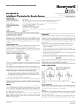
Wiring Guide
Refer to the installation instructions for the particular plug-
in base being used: 1) for the B501B base (D550-01-01); 2)
for the B501 base (D550-02-00); 3) for the RMK400 used
with the B501 base (D450-07-00). Bases are provided with
screw terminals for power, ground, and remote annunciator
connections (see Figure 1).
NOTE: All wiring must conform to applicable local codes,
ordinances, and regulations.
NOTE: Verify that all sensor bases are installed and that
the wiring polarity is correct at each base.
WARNING
Remove power from the loop before installing sensors.
1. Install sensors:
a. Verify that the sensor type matches the type written
on the label on the base.
b. Set the sensor to a desired address and then write the
address on the label on the base.
c. Place the sensor into the sensor base.

D500-04-00 2 I56-292-05
d. Turn the sensor clockwise until it drops into place.
e. Continue turning the sensor clockwise until it locks
into place.
WARNING
Sensor will not detect smoke if dust cover is installed.
2. Tamper-proof feature:
The sensor bases include a tamper-proof feature that,
when activated, prevents removal of the sensor without
the use of a tool. See the installation instruction manual
for the sensor base for details in using this feature.
3. After all sensors have been installed, apply power to the
control unit.
4. Test all sensors per the TESTING section of this manual.
3
2
1
3
2
1
3
2
1
+
-
-
+
U.L. LISTED COMPATIBLE
CONTROL PANEL
CLASS A OPTIONAL WIRING
REMOTE ANNUNCIATOR
+-
CAUTION: Do not loop wire under terminal 1 or 2.
Break wire run to provide supervision of connections.
A78-1253-01
Figure 1. Wiring Diagram:
LED
LED
TEST MODULE
SOCKET
TEST
MAGNET
PAINTED
SURFACE
TEST
MAGNET
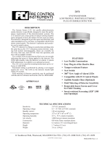
Figure 2. Views showing position of test magnet (model 2551T shown):
A78-1410-01
Testing
Before testing, notify the proper authorities that the smoke
sensor system is undergoing maintenance, and therefore
the system will temporarily be out of service. Disable the
zone or system undergoing maintenance to prevent un-
wanted alarms.
Sensors must be tested after installation and periodic main-
tenance. The sensor may be tested in the following ways:
A. Test Magnet (Model No. M02-04-00)
1. Place the magnet against the cover opposite the test
module socket to activate the test feature (see Figure 2).
2. The LEDs should latch on within 10 seconds indicat-
ing alarm and annunciating the panel.
B. Test Module (Model No. MOD400R)
The MOD400R is used with your DMM or voltmeter to
check the sensor sensitivity as described in the
MOD400R’s manual.

D500-04-00 3 I56-292-05
NOTE: If the sensor’s sensitivity limits or the MOD400R
limits do not appear on the back of the sensor, the
MOD400R is not suitable for field sensitivity test-
ing of that unit.
C. Smoke Entry Test per NFPA 72
The field test tool is the Gemini Model 501 aerosol gener-
ator. Set the generator to represent 4%/ft to 5%/ft ob-
scuration as described in the Gemini 501 manual. Using
the bowl shaped applicator, apply aerosol until unit
alarms. If the Gemini unit is not available, a punk, cot-
ton wick, or cigarette are acceptable means of generating
smoke to test all System Sensor ionization and photo-
electronic sensors.
NOTE: This test only verifies proper operation of the sen-
sor and is not used to test sensitivity.
D. Direct Heat Method (Hair dryer of 1000-1500 watts)
Direct the heat toward the thermal collector. Hold the
heat source about 12 inches from the detector in order to
avoid damage to the plastic. The detector will reset only
after the collector has had sufficient time to cool and the
power source has been momentarily interrupted.
After testing, detectors must be reset from the control
panel. Notify the proper authorities that the system is back
on line.
Sensors that fail these tests should be cleaned as described
under CLEANING and retested. If the sensors still fail these
tests they should be returned for repair.
CAUTION
Dust cover is not a substitute for removing sensor during
new construction or heavy remodeling. Cover only helps
limit dust entry.
Cleaning the Sensor
NOTE: Before cleaning, notify the proper authorities that
the smoke sensor system is undergoing mainte-
nance and will temporarily be out of service. Dis-
able the loop or system undergoing maintenance to
prevent unwanted alarms.
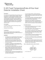
It is recommended that the sensor be removed from its
mounting base to facilitate easier cleaning (see Figure 3).
The sensor is cleaned as follows:
1. Remove the sensor cover by placing a small bladed
screwdriver in the side slot of the sensor cover, twisting
it slightly until the cover can be turned counterclockwise
for removal.
2. Vacuum the screen carefully without removing it. If fur-
ther cleaning is required continue with Step 3, otherwise
skip to Step 6.
3. Remove the screen by pulling it straight out. Vacuum the
inside.
4. Clean the vaned chamber piece by vacuuming or blow-
ing out dust and particles.
5. To replace the screen, orient it so that the arrow on top
aligns with the field test slot on the base of the detector.
Carefully push the screen onto the base making sure it
fits tightly to the chamber.
6. Replace the cover by gently rotating it clockwise until it
locks in place.
A78-1941-01
REMOVABLE COVER
REMOVABLE SCREEN
P/N RS24 (W/O THERMAL)
RS24T (W/THERMAL
TEST SLOT
Figure 3:

D500-04-00 4 I56-292-05
© System Sensor 1996
Three-Year Limited Warranty
System Sensor warrants its enclosed smoke detector to be free from de-
fects in materials and workmanship under normal use and service for a
period of three years from date of manufacture. System Sensor makes no
other express warranty for this smoke detector. No agent, representative,
dealer, or employee of the Company has the authority to increase or alter
the obligations or limitations of this Warranty. The Company’s obligation
of this Warranty shall be limited to the repair or replacement of any part of
the smoke detector which is found to be defective in materials or work-
manship under normal use and service during the three year period com-
mencing with the date of manufacture. After phoning System Sensor’s toll
free number 800-SENSOR2 (736-7672) for a Return Authorization number,
send defective units postage prepaid to: System Sensor, Repair Depart-
ment, RA #__________, 3825 Ohio Avenue, St. Charles, IL 60174. Please
include a note describing the malfunction and suspected cause of failure.
The Company shall not be obligated to repair or replace units which are
found to be defective because of damage, unreasonable use, modifica-
tions, or alterations occurring after the date of manufacture. In no case
shall the Company be liable for any consequential or incidental damages
for breach of this or any other Warranty, expressed or implied whatsoever,
even if the loss or damage is caused by the Company’s negligence or fault.
Some states do not allow the exclusion or limitation of incidental or conse-
quential damages, so the above limitation or exclusion may not apply to
you. This Warranty gives you specific legal rights, and you may also have
other rights which vary from state to state.
This smoke detector is designed to activate and initiate emergency ac-
tion, but will do so only when it is used in conjunction with an authorized
fire alarm system. This detector must be installed in accordance with
NFPA standard 72.
Smoke detectors will not work without power. AC or DC powered
smoke detectors will not work if the power supply is cut off.
Smoke detectors will not sense fires which start where smoke does not
reach the detectors. Smoldering fires typically do not generate a lot of
heat which is needed to drive the smoke up to the ceiling where the
smoke detector is usually located. For this reason, there may be large de-
lays in detecting a smoldering fire with either an ionization type detector
or a photoelectric type detector. Either one of them may alarm only after
flaming has initiated which will generate the heat needed to drive the
smoke to the ceiling.
Smoke from fires in chimneys, in walls, on roofs or on the other side of a
closed door(s) may not reach the smoke detector and alarm it. A detector
cannot detect a fire developing on another level of a building quickly or at
all. For these reasons, detectors shall be located on every level and in
every bedroom within a building.
Smoke detectors have sensing limitations, too. Ionization detectors and
photoelectric detectors are required to pass fire tests of the flaming and
smoldering type. This is to ensure that both can detect a wide range of
types of fires. Ionization detectors offer a broad range of fire sensing capa-
bility but they are somewhat better at detecting fast flaming fires than
slow smoldering fires. Photoelectric detectors sense smoldering fires better
than flaming fires which have little, if any, visible smoke. Because fires de-
velop in different ways and are often unpredictable in their growth, nei-
ther type of detector is always best, and a given detector may not always
provide early warning of a specific type of fire.
In general, detectors cannot be expected to provide warnings for fires re-
sulting from inadequate fire protection practices, violent explosions, es-
caping gases which ignite, improper storage of flammable liquids like
cleaning solvents which ignite, other similar safety hazards, arson, smok-
ing in bed, children playing with matches or lighters, etc. Smoke detectors
used in high air velocity conditions may have a delay in alarm due to dilu-
tion of smoke densities created by frequent and rapid air exchanges. Addi-
tionally, high air velocity environments may create increased dust
contamination, demanding more frequent maintenance.
Smoke detectors cannot last forever. Smoke detectors contain electronic
parts. Even though smoke detectors are made to last over 10 years, any
part can fail at any time. Therefore, smoke detectors shall be replaced after
being in service for 10 years. The smoke detector system that this detector
is used in must be tested regularly per NFPA 72. This smoke detector
should be cleaned regularly per NFPA 72 or at least once a year.
WARNING
The Limitations of Property Protection Smoke Detectors
/