Page is loading ...

SWARS
OWNER'S
MANUAL
Model No,
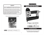
351.183230
Caution:
Read and follow
all safety rules and
operating instructions
before first use of this
product.
[RRFTSHRN
18 Gauge Brad Nailer
• Safety Instructions
•, Operation
• Maintenance
• Troubleshooting
• Parts List
Sears, Roebuck and Co., Hoffman Estates, IL 60179 U.S.A.
Part No. 9021.00 December 1995

DESCRIPTION
The SearsCraftsman18Gauge BradNailerdrivesbradsl'rom
V."to 2" long, Die cast aluminum textured finish body reduces
operator fatique. Large capacity, side loading magazine with
positive, quick action latch makes loading easy. Contact safe-
ty disables nailer unless nosepiece is in contact with work-
piece. Tapered nosepiece provides operator with greater visi-
bility for precise brad placement. Rigid nosepiece reduces
jamming. The gears 18 Gauge Brad Nailer is excellent for
molding and decorative trim, furniture making and picture
framing.
SAFETY INSTRUCTIONS
• Air tool operators and all others in work area should always
wear safety goggles (must comply with ANSI Z87.1) to
prevent eye injury from fasteners and flying debris when
loading, Ol_rating or unloading this tool.
• Never exceed operating pressure of 100 PSI (7,1 kg/em').
• Always keep hands and body away from the fastener dis-
charge area when air supply is connected to tool.
• Always disconnect tool from air supply when servicing or
adjusting tool end when tool is not in use,
• Do not operate tool when nose is not in contact with work.
• Never load the tool until you are ready to use it.
• Never depress tool trigger when loading.
• Always load tool with nose pointing away from you and
others.
• Never point tool at yourself or others,
• Never carry tool with trigger depressed.
• Do not use oxygen, combustible gas or high pressure com-
pressed gas as the air supply for the tool.
• Always use tool at safe distance from other people in work
area.,
• Do not attempt to discharge tkstener into hard or brittle
materials such as concrete, steel or tile.
• Do not connect female quick-disconnect ctmpiing to tool
side of air line.
• Connect male, free-flow nipple to tool side of air line so
that tool is depressurized when diSconnected from hose,
• Do not use a hose swivel with this tool.
• Use Sears recommended fasteners only.
SPECIFICATIONS
Capacity ............................. 100 brad nails
Brad nail size .................. 18 gauge (.049 x .040")
Brad nail Icnglhs ............................ ¼ to 2"
Operating pressure ....................... 60-100 PSI
Air inlet ............................... V,"F.N.P.T.
Length ...................................... 9'/,"
lleight ...................................... 9'/,."
Width ....................................... 2_,_"
Weight ................................... 3.5 Ibs.
Brad Nails
_]8341 ................... 18 gauge brad nails, V," hn_g
_18342 ................... 18 gauge brad nails, l" long
t] 8343 .................. 18 gauge brad nails, 1'A"long
918360 .................. ] 8 gauge brad nails. 1'/_"long
918361 .................. 18 gauge brad nails, 1)/," hmg
t18362 .................... 18 gauge brad nails 2" long
OPE" RATING INSTRUCTIONS
Air Supply Line
Refer to Figure 1.
• The Sears brad nailer operates on compressed air at pres-
sures fi'om 60 to 100 PSI.
• Never exceed maximulla pressure.
Minimum air requirements for nailer: Average working
SCFM 3.2 at 90 Pal.
WARNING; KEEP HANDS AND BODY AWAY FROM
DISCHARGE AREA OF TOOL WlIEN
CONNECTING AIR SUPPLY. ALWAYS
DISCONNECT TOOL FROM AIR SUPPLY
WHEN SERVICING OR ADJUSTING
TOOL AND WHEN TOOL IS Nor IN USE.
-.. a
Figure 1-Air _upply Line
2

• Clean dry air is essential to the operation of the Sears nation
* Air operated tools require clean, dry, lubricated com-
pressed air to ensure top performance, low maintenance
and long life.
• Dirt and abrasive materials presem in all air lines will dam-
age tool O-rings, valves and cylinders.
• Moisture will reduce tool performance and life if not
removed from compressed air,
• A filter-regulator-lubricator system is required and should
be located as close to tool as possible (see Figure l). A dis-
lance of less than 15 feet is recommended
• Keep air filter clean. A dirty filter will reduce the air pres-
Nnlo: For best results use Sears nails only,
• Depress latch (Key No, 59) and slide magazine cover (Key
No. 52) backwards (see Figure 2). Insert brad nails into
magazine. Position brads at bottom of magazine with brad
head towards top of tool.
• Slide cover forward over magazine until latch snaps into
place, locking magazine cover.
Note: It may be necessary to depress latch handle to close
magazine cover.
Nailing Operation
WARNING: NEVER OPERATE TOOL UNLESS CON-
sure to the nailer causing a reduction in power and effi-
ciency.
• The air supply _atem must be able to provide air pressure
of 60 to 100 pounds per square inch at tool.
• The lubricator should be filled with a non-detergent air tool
oil.
• All hoses and pipes in the air supply system must be clean
TACT "/'RIP IS IN CONTACT WITtl
WORKPIECE. DO NOT OPERATE TOOL
WITHOUT NAILS OR DAMAGE TO
TOOL MAY RESULT. NEVER FIRE NAILS
INTO THE AIR BECAUSE NAILS MAY
INJURE OPERATOR OR OTHERS AND
DAMAGE TO TOOL MAY RESULT.
and free of all moisture and foreign panicles.
• Never connect a female quick disconnect coupling to the
tool side of air system. A male, free-flow coupling should
be connected to the tooi side of air system.
The female coupling provides a seal preventing loss of
compressed air from compressor tank when disconnected
from male coupling. If connected to tool side of air supply,
the female coupling could seal a compressed air charge in
the nailer which could discharge if the tool trigger is actu-
ated.
• The Sears 18 Gauge Brad Nailer is equipped with a contact
trip safety mechanism (see Figure 3) that disables nailer
unless contact trip is pushed against work. Hold tool han-
dle firmly and press nose of tool on workpiece where nail
is to be applied. Pull trigger to drive hall into workpiece.
• The nailer can also be operated by holding trigger
depressed and pushh_g contact trip against workpiec¢. This
operating procedure provides rapid-fire nail driving. Never
operate tool unless contact trip is in contact with work-
piece.
• The air pressure should be properly regulated.
• Different work'piece materials and different nail lengths
wiU require different operating pressure.
Loading
Refer to Figures 2 & 5 (pages 3 and 6).
WARNING: DISCONNECT TOOL FROM AIR SUPPLY.
ALWAYS LOAD WITH NOSE POINTING
AWAY FROM YOU AND OTHERS.
ALWAYS WEAR SAFETY GOGGLES
THAT COMPLY WITH ANSI Z87.1.
Figure 2-Loading Brad Nails
Figure 3-Contact Trip Operation
3

Operating Instructions (continued)
Quick Release Nose
Refer to Figure 5 (page 6).
The Sears 18 Cruage Brad Nailer is equipped with a quick
release nose for clearing jammed nails.
* Ira nail jams in the tool, disconnect the air supply from the
too!. Open the magazine and remove any nails. Pull the
nose cover latch (Key No. 37) down and release the nose
cover. Remove the jammed nail and secure the latch,
Reload the nails and connect the air supply.
Operating Pressure
• Use only enough air pressure to perform the nailing opera-
tion. Air pressure in excess of that which is required will
make the nailing operation inefficient and may cause pre-
mature wear or damage to the tool.
.. Determine minimum air pressure required by driving some
re,stnails into the workpiece. Set air pressure so that test
nails heads are driven down flush with the work. Nails dri-
ven too deep may damage workpiece.
Exhaust Deflector
Refer to Figures 4 & 5 (pages 4 and 6).
* The position of the exhaust deflector can be changed to
direct exhaust as desired. Exhaust deflector can be posi-
tioned at the left, front or right side of lOOt. Reposition
deflector (Key No. 6) by carefully removing four bolts
(Key No. 4) and rotating deflector to desired position.
• Be sure not to _nlsplace valve spring (Key No. 7). Secure
four bolts making sure that valve spring and exhaust plate
are properly positioned.
Figure 4-Exhaust Deflector Adjustment
MAINTENANCE
Lubrication
Refer to Figure 5 (page 6),
Lubricate tool daily with quality air tool oil. If no air hoe lubri-
cator is used, pour five to six drops of oil into air inlet (Key
No, 3) of nailer eyeD,day.
• Keep magazine and nose clean and free of any dirt, lint or
abrasive particles,
The tip of the ram (Key No. 17) can become dented or round-
ed over time.
• Square of]"the tip of the ram with a clean, fine hand. file to
extend the life of the ram arid nailer, Nail firing will be
more consistent if the ram tip is kept clean and square.
Safety Mechanslm
Inspect oontact trip safizty mechanism daily for proper opera.
tion. Do not operate nailer if mechanism is not operating prop-
erly.
PcrJorm the following procedures to test safety mechanism:
• I,eave trigger untouched while pushing contact trip into
workpiece. Nailer must not fire.
• Pull nailer trigger while contact trip is clear of work and
pointed away fi'om operator ,_nd others. Nailer must not
fire.
• Depress anti hold trigger. Push contact trip against work
where nail is needed. The nailer should drive only one nail
each time the contact tril_ is pushed against workpicce,
If contact trip mechanism does no! operate properly,
repair nailer immediately threugh Sears Service Center.
Replace any damaged or missing pans. Use the parts list to
order parts,
Piston/Ram Assembly
Refer to Figure 5 (page 6).
Tip of' the ram (Key No. 17) can be dented or rounded over
time. Square off tip of ram with a €lcan, fine hand file to
extend the life of ram and nailer. Nail firing will be more con-
sistent if the ram tip is kept clean and square,
Rebuild Kits
Rebuild kits are available as spare parts, see page 7. Tools
should be rebuilt if tool fails to operate properly after extend-
ed use. See troubleshooting to _.etermine required replacement
parts.
Disconnect toni from air supply before attempting repair
or adJuslment.
NOTE: Be sure tool is oiled properly. Clean and oil O-rings
during reassembly.
4

TROUBLESHOOTING
Symptom
Triggercap leaksair
Triggerleaksair
Cap leaksair
Nose leaks air
Tool will not operate
Tool operates slowly
or loses power
Toolskipsnailsor
inconsistentoperation
Possible C=use(=)
O-ringdamaged
Damaged sealandre O-rings
1. Cap bolts loose
2. Damaged O-ring and gasket
1, Nose bolts loose
2. Damaged cylinder O-ring
3. Damaged Bumper
1, Insufficient air supply
2. Insufficient lubrication
3. Damaged or worn head valve O-rings
4, Broken head valve spring
5. Head valve binding
1, Insufficient lubrication
2. Head valve spring doesn't work
3, Damaged or worn O-rings
4. Damaged trigger assembly
5, Build-up on ram
6. Cylinder not sealed on bumper
7. Head valve poorly lubricated
8, Insufficient air supply
1'. Worn or damaged bumper
2. Build-up on ram or nose
3, Insufficient air supply
4. Damaged or worn piston O-ring
5. Insufficient lubrication
6. Damaged magazine springs
7. Magazine-nose bolts loose
8. Nails too short
9. Damaged nails
10. Incorrect nail size
11. Head valve O-rings leak
12. Damaged seal and O-rings
13. Bent or damaged ram
14. Dirty magazine
15. Damagedorworn magazine
Corrective Action
Check and replace damaged O-ring (Key No.29)
Check and replacedamagedseal and O-rings
(KeyNos. 24, 28, and 29)
t. Tighten bolts (t ay No. 4)
2. Check and replace damaged O-ring and gasket
(Key Nos. 10 and 11)
1. Tighten nose bolts (Key No, 40)
2, Check and replace damaged O-ring (Key No, 19)
3. Check and replace damaged bumper
• (Key No. 22)
1. Check air supply
2, Place five or six drops of air tool oil into inlet cap
(Key No. 3)
3. Replace damaged or worn O-rings
(Key Nos. 12 and 14)
4. Replace broken spring (Key No. 7)
5. Clean and lubricate valve and cap
(Key Nos. 9 and 13)
1. Place five or six drops of air tool oil into inlet cap
2, Check and replace spring (Key No. 7)
3. Check and replace damaged or worn O-rings
4. Check and replace trigger assembly
5. Clean and lubricate piston/ram assembly
(Key No, 17)
6. Disassemble cylinder and assemble properly
7. Disassemble head valve (Key No. 13), clean and
lubricate. Assemble properly
8. Check air supply
1. Check and replace bumper (Key No. 22)
2, Clean and lubricate piston/ram assembly
(Key No. 17) and inside of nose cover (Key No. 38)
3. Check air supply
4. Check and replace O-ring (Key No. 16)
5. Place five or six drops of air tool oil into Inlet cap
(Kay No. 3)
6. Check and replace springs (Key No. 48)
7. Tighten bolts (Key No, 40)
8. Use Sears recommended nails only
9, Discard damaged nails. Use Sears recommended
nails only.
10. Use Sears recommended nails only
11, Check and replace damaged O-rings
(Key Nos. 12 and 14)
12. Check and replace damaged seal and O-rings
(Key Nos. 24, 28 and 29)
13. Check end replace damaged piston/ram assembly
(Key No. 17)
14. Clean magazine and lubricate with air tool oil
15. Check and replace magazine (Key No. 49)
5

/
/
4O
Rim 5-Rq)lacemem Forts For Brad Nailer
6

Replacement Parts List
KEY PART
NO. NO. DESCRIPTION QTY.
1 9006.00 Body 1
2 9007.00 Inlet cap O-ring f
3 9008.00 Inlet cap 1
4 5264.00 5-0.8 x 25mm Socket head bolt 4
5 STD852005 5ram Lock washer 6
6 9009.00 Deflector 1
7 6047.00 Spring 1
8 6048.00 Seal 1
9 9010.00 Cap 1
10 6050,00 13.8 x 2.4ram O.,dng 1
11 9011.00 Gasket 1
12 ' 6052.00 31.8 x 2.4mm O-ring 1
13 6053.00 Head valve 1
14 6054.00 23 x 3.5mm O-ring 1
15 6055.00 Deflector _y[inder 1
16 6056.00 21.7 x 2.9ram O-ring 1
17 90t2.00 Piston-ram assembly 1
18 9013.00 Cylinder 1
19 9014,00 29.2 x 3.5mm O-ring 1
20 9015.Q0 Spacer 1
21 901"6.00 43 x 2.4mmO-ring I
22 9017.00 Bumper 1
123 6061.00 Ram guide 1
_ 6065.00 Plasticseal 1
9018.00 Trigger valve head 1
26 9019.00 Spring 1
27 9020.00 Plunger 1
28 6167.00 2.5 x 1.5mm O-ring 2
29 8069.00 13 x 2mm O-ring 1
30 9022,00 Trigger cap 1
31 6074.00 Trigger lever 1
KEY PART
NO. NO. DESCRIPTION QTY.
32 6072.00 Trigger 1
33 6075.00 2.5 x 16mm Spring pin 2
34 6073.00 Clevis pin 1
35 46-221434-9 3CMI-3 E-ring 2
36 6079.00 4-7.0 x 16ram Socket head boll 1
37 9023,00 Nose cover latch 1
38 9024.00 Nose cover 1
39 9025.00 Nose plate 1
40 ' 6097.00 4-.70 x 14ram Socket head bolt 4
41 9026.00 Contact trip 1
42 9027.00 Spring 1
43 6164.00 3 x 25ram SDring pin 2
44 9028.00 Bracket 1
45 9029.00 Nose 1
46 9030.00 Pusher bracket lj
47 9031.00 Pusher 2
!48 6092.00 Pusher spring 2
49 9032.00 _Magazine 1
_50 6093.00 !Wear plate 1
51 9033.00 2.5 x 12mm Spring pin 2
52 9034.0()' Magazine cover 1
53 9035.00 Latch plate 1
54 6076.00 4-0.7 x 12mm Socket head boll 2
55 STD852004 4ram Lock washer 2
56 6080.00 4mm-,70mm Fiber hex nut 1
57 9036,00 'Latch Bracket 1
58 6084.00 Latch spring 1
59 6083.00 Latch 1
60 5809.00 4-.70 x 6ram Socket head bolt 2
61 6045.00 5-0,8 x 20mm Socket head boll 2
62 6987.00 Clevis pin 1
• 9021.00 Owner's Manual 1
* Standard hardware item available locally
• Not Shown
RECOMMENDED ACCESSORIES
• 18 Gauge Brad Nai!s, %" Long 918341
• 18 Gauge Brad Nails, 1" Long 918342
• 18 Gauge Brad Nails, 11,_"Long 918343
• 118 Gauge Brad Nails, 1V="Long 918360
• 18 Gauge Brad Nails, 1=/4"Long _18361
• 18 Gauge Brad Nails, 2"Long 918362
REBUILD KITS
• Trigger Rebuild Kit 1
Key Nos.24, 25. 27, 29, and
2 ea, 28
7
9037.00
9038.00
9039.00
I
;9040.00
Head Valve Rebuild Kit 1
Key Nos,8, 10, 11, 12, and 14
Piston Ram Assembly Rebuild Kil 1
Key No. 16, 17, 22, and 23
Cylinder Rebuild Kit 1
Key Nos. 19 and 2I

SWARS
OWNER'S
MANUAL
Model No.
351,183230
When requesting service
or ordering parts, always
Iprovide the following
information:
• Product Type
• Model Number
• Part Number
• Part Description
CRRFTSMRN
18 Gauge Brad Nailer
For the repair or replacement parts you need
Call 7 am - 7 pro, 7 days a week
1-800-366-PART
(1-800-366-7278)
For the location of a
Sears Repair Service Canter In your area
Call 24 hours a day, 7 days a week
1-800-488-1222
B=llliBm
SEARS
America's ReD_ir _oeciallsts
J
Full One Year Warranty On Craftsman Air-Drive Tools
If this Craftsman air-drive tool falls to give complete satisfaction within one full year from
the date of purchase, RETURN IT TO THE NEAREST SEARS SERVICE CENTER/DEPARTMENT IN
THE UNITED STATES, and Sears will repair It free of charge.
If this air-drive tool is used for commercial purposes, this warranty applies for
only 90 days from the date of purchase.
This warranty gives you specific legal rights and you may also have other rights which
vary from state to state,
Sears, Roebuck and Co., Dept. D/817 WA, Hoffman Estates, IL 60179
Sears, Roebuck and Co., Hoffman Estates, IL 60179 U.S.A.
Part No, 9021.00 December 1995
/