Page is loading ...

1
4 rue d'Arsonval - BP 70091
95505 GONESSE cedex
Phone: +33 (0) 1 34.07.71.00
Fax: +33 (0) 1 34.07.71.01
www.bernardcontrols.com
User manual
INTELLI+ SIL OMM

Invest in confidence
NR1214 EN - INTELLI+ SIL Manual ind. F - INTELLI+ SIL OMM
2
Record of revisions
Index
Date
Modification
Written
by:
Checked
by:
Approved
by:
0
04/13
Creation
F. Drieux
G. Faure
D.Schwebel
L.Maissin
T.Bourin
J. Medarhri
A
07/13
Modification after check by after sales
department (T.Bourin) and comments.
F. Drieux
G. Faure
D.Schwebel
L.Maissin
T.Bourin
J. Medarhri
B
07/13
Addition of §6 section: periodic checks following
Clearsy notification sheet
O. Jean
G. Faure
D.Schwebel
L.Maissin
T.Bourin
J. Medarhri
C
09/13
Paragraph added on the scope and purpose of
the document following BV comment §2
Paragraph added on the overall product
description following BV comment §3.1
Modification of §4.7.2 on electrical priority of
ASM/ST6
Added delivery of IMP094 test sheet in §3.10
O. Jean
J.MEDARHRI
G. Faure
D.Schwebel
L.Maissin
T.Bourin
J. Medarhri
D
03/14
E009:
Update of paragraph number page 48
Password for SIL Validation : §4.5.2 > §5.5.2
F. Drieux
G. Faure
J. Medarhri
E
07/14
E065:
Addition of a SIL Requirement putting in
responsibility the user on the sizing of the valve.
F.BOUGET
G.FAURE
J.MEDARHRI
F
03/17
DM_17031:
Modification of EX_SEC_REG_20130726_1
requirement to modify periodical checking
value.
Correction of SQX range extent
T.MILAN
F.BAYLE
J.MEDARHRI

Invest in confidence
NR1214 EN - INTELLI+ SIL Manual ind. F - INTELLI+ SIL OMM
3
Content
Record of revisions ........................................................................................................................... 2
Content .............................................................................................................................................. 3
1. FOREWORD ............................................................................................................................. 6
2. PRESENTATION ....................................................................................................................... 6
2.1. BERNARD CONTROLS ACTUATORS ............................................................................................... 6
2.2. SIL ACTUATORS ........................................................................................................................... 7
2.2.1. CE directives compliance ............................................................................................................... 7
2.3. INTELLI+ ...................................................................................................................................... 7
2.4. Safety Integrity Level (SIL) ........................................................................................................... 8
2.5. SIL requirements ....................................................................................................................... 10
2.6. MODELS PRESENTATION ........................................................................................................... 12
2.7. Explosion-proof range ............................................................................................................... 13
2.7.1. STX6 to STX140 (built-in electronics) ........................................................................................... 13
2.7.2. ST175 to ST220 ADF (built-in electronics) ................................................................................... 14
2.7.3. SQX18 to SQX80 (built-in electronics) ......................................................................................... 14
2.7.4. FPx casing with electronics, separate .......................................................................................... 14
2.8. Weatherproof range .................................................................................................................. 15
2.8.1. ST6 to ST220 (electronics in adjacent FPi casing) ........................................................................ 15
2.8.2. SQ20 to SQ80 (electronics in adjacent FPi casing) ...................................................................... 16
2.8.3. ASM0 to ASM3 (electronics in adjacent FPi casing) .................................................................... 16
2.8.4. FPi casing with electronics, separate ........................................................................................... 16
2.9. Actuators characteristics ........................................................................................................... 17
2.9.1. Environmental characteristics ..................................................................................................... 17
2.9.2. Devices ......................................................................................................................................... 18
2.9.3. Grease .......................................................................................................................................... 19
2.9.4. Separate casing ............................................................................................................................ 19
2.10. REFERENCE DOCUMENTATION ............................................................................................... 20
2.11. SAFETY .................................................................................................................................. 21
3. TRANSPORT AND INSTALLATION ......................................................................................... 21
3.1. ON-SITE SAFETY ........................................................................................................................ 21
3.2. NECESSARY EQUIPMENT............................................................................................................ 21
3.3. STANDARD PACKAGINGS ........................................................................................................... 21
3.4. STORAGE .................................................................................................................................. 22
3.4.1. Storage conditions ....................................................................................................................... 22
3.4.2. Storage requirements .................................................................................................................. 22
3.5. INSTALLATION PROCEDURE SYNOPTIC ....................................................................................... 23
3.6. UNPACKING CHECKS .................................................................................................................. 24
3.6.1. Before unpacking ......................................................................................................................... 24
3.6.2. After unpacking ........................................................................................................................... 24
3.6.3. SIL marking .................................................................................................................................. 25
3.6.4. ST/SQ/ASM marking .................................................................................................................... 25
3.6.5. ST175/ST220 explosion-proof versions marking ......................................................................... 26
3.6.6. SQX/STX versions marking ........................................................................................................... 26
3.6.7. Separate FPx casing marking ....................................................................................................... 27
3.7. MECHANICAL INSTALLATION ..................................................................................................... 28

Invest in confidence
NR1214 EN - INTELLI+ SIL Manual ind. F - INTELLI+ SIL OMM
4
3.7.1. Installation compliance................................................................................................................ 28
3.7.2. Handwheel ................................................................................................................................... 28
3.7.3. Lifting ........................................................................................................................................... 29
3.7.4. Coupling types ............................................................................................................................. 31
3.7.5. Valve installation ......................................................................................................................... 33
3.8. ELECTRICAL CONNECTION – WEATHERPROOF RANGE ................................................................. 35
3.8.1. Presentation of the FPi casing ..................................................................................................... 35
3.8.2. Connection box ............................................................................................................................ 35
3.8.3. Orientation .................................................................................................................................. 36
3.8.4. Selector cover .............................................................................................................................. 36
3.8.5. ST/SQ/ASM connection ............................................................................................................... 37
3.8.6. ST175/ST220 connection ............................................................................................................. 39
3.8.7. Separate FPi casing ...................................................................................................................... 39
3.9. ELECTRICAL CONNECTION – EXPLOSIONPROOF RANGE .............................................................. 40
3.9.1. Presentation ................................................................................................................................ 40
3.9.2. Connection box ............................................................................................................................ 40
3.9.3. Electrical connection ................................................................................................................... 41
3.9.4. BU casing ..................................................................................................................................... 43
3.9.5. Selector cover .............................................................................................................................. 43
3.9.6. Separate FPX casing ..................................................................................................................... 44
3.10. POWERING UP ....................................................................................................................... 44
4. SIL SETUP AND COMMISSIONING ........................................................................................ 45
4.1. HOW TO NAVIGATE IN THE MENUS ........................................................................................... 46
4.1.1. Presentation of selectors ............................................................................................................. 46
4.1.2. Going to the main menu .............................................................................................................. 46
4.1.3. Select a menu or section ............................................................................................................. 46
4.1.4. Save modifications ....................................................................................................................... 47
4.1.5. Quit the menu at any time .......................................................................................................... 47
4.1.6. Description of the main menu ..................................................................................................... 47
4.2. SELECT THE MENU LANGUAGE ................................................................................................... 47
4.3. PASSWORD ............................................................................................................................... 48
4.4. ORGANISATIONAL CHART .......................................................................................................... 49
4.4.1. Organisational chart of the CHECK menu .................................................................................... 49
4.4.2. Organisational chart of the CHANGE menu ................................................................................. 50
4.4.3. Organisational chart of the SIL SETUP and SIL VALIDATION menu ............................................. 51
4.4.4. Organisational chart of the BUS SUB-MENU ............................................................................... 52
4.5. HOW DO YOU ADJUST AN ACTUATOR ON A VALVE ? .................................................................. 53
4.5.1. SIL SETUP ..................................................................................................................................... 53
4.5.2. SIL VALIDATION............................................................................................................................ 55
4.6. LOCAL COMMAND .................................................................................................................... 56
4.6.1. Presentation of local controls ...................................................................................................... 56
4.6.2. Local control ................................................................................................................................ 56
4.6.3. Local stop ..................................................................................................................................... 56
4.7. REMOTE COMMAND ................................................................................................................. 57
4.7.1. Auto / On-Off settings ................................................................................................................. 57
4.7.2. Contact command ....................................................................................................................... 58
4.7.3. Voltage command ........................................................................................................................ 58
4.7.4. Single contact command ............................................................................................................. 59
4.7.5. Remote stop ................................................................................................................................ 59
4.7.6. Priority to opening or closing ...................................................................................................... 60

Invest in confidence
NR1214 EN - INTELLI+ SIL Manual ind. F - INTELLI+ SIL OMM
5
4.8. HOW DO YOU READ AND ADJUST THE TORQUE ? ....................................................................... 61
4.8.1. Torque setting ............................................................................................................................. 61
4.8.2. Read the measured torque values and compare them to the original torque values ................ 62
4.9. SIGNALISATION ......................................................................................................................... 64
4.9.1. Presentation of the display unit .................................................................................................. 64
4.10. HOW TO CUSTOMISE THE INDICATIONS? ............................................................................... 65
4.10.1. Local Indication ............................................................................................................................ 65
4.10.2. Remote signalisation ................................................................................................................... 65
4.11. USE AS POSITIONER BASED ON AN ANALOGUE CONTROL SIGNAL (ACCORDING TO THE DEVICE)
68
4.11.1. Input signal .................................................................................................................................. 68
4.11.2. Adjusting the dead band ............................................................................................................. 69
4.11.3. Fallback position .......................................................................................................................... 69
4.11.4. Proportional pulses ...................................................................................................................... 69
4.12. LOCAL COMMUNICATION BY PC ............................................................................................. 70
4.12.1. Communication by infrared ......................................................................................................... 70
4.12.2. Communication by bluetooth (option) ........................................................................................ 70
4.13. HOW TO INTRODUCE A TIME DELAY DURING OPERATION ...................................................... 72
4.14. HOW TO SEE THE ACTUATOR ACTIVITY? ................................................................................. 73
4.14.1. Activity ......................................................................................................................................... 73
4.15. HOW TO LOOK UP AN ALARM ? ............................................................................................. 74
4.15.1. SIL Alarms : .................................................................................................................................. 74
4.15.2. No SIL failure ................................................................................................................................ 76
4.16. HOW TO ACCESS THE TECHNICAL DATA SHEET ? ..................................................................... 77
4.17. USE OF THE FIELDBUS CONTROL (ACCORDING TO THE DEVICE) ........................................... 79
4.18. FUSE PROTECTION ................................................................................................................. 81
4.19. SIL FUNCTIONS (SIL2 certified) ............................................................................................... 81
4.19.1. SIL Signalisation ........................................................................................................................... 81
4.19.2. ESD SIL Commands (SIL2 certified) .............................................................................................. 83
4.20. SIL POSITION FEEDBACK (SIL2 certified) .................................................................................. 84
4.21. OPERATING ERROR ................................................................................................................ 85
5. PERIODIC CHECKS (T1) ........................................................................................................... 87
5.1. CAS D’APPLICATION .................................................................................................................. 87
5.2. CHECKS TO BE PERFORMED ....................................................................................................... 88
6. MAINTENANCE ...................................................................................................................... 89
6.1. EEPROM.................................................................................................................................... 89
6.2. WHEEL/SCREW .......................................................................................................................... 89
6.3. ENCODER .................................................................................................................................. 89

Invest in confidence
NR1214 EN - INTELLI+ SIL Manual ind. F - INTELLI+ SIL OMM
6
1. FOREWORD
This document is intended for technicians who install, commission and maintain BERNARD
CONTROLS actuators equipped with SIL level INTELLI+ interface.
By observing procedures detailed in this document, technician must ensure the full compatibility
of BERNARD CONTROLS actuator with the operating requirements.
2. PRESENTATION
2.1. BERNARD CONTROLS ACTUATORS
BERNARD CONTROLS actuators are mainly designed to operate industrial valves.
According to the valve, they can provide two types of movements:
Quarter turn (SQ and SQX ranges)
Multi-turn (ST, STX and ASM ranges)
They can be used in demanding conditions such as wet areas (SQ, ST, ASM weatherproof
actuators) or explosive atmospheres (explosion-proof ST175 and ST220 ATEX actuators, STX,
SQX).
Thus, there is a wide range of models covering the different torque levels.
Whatever their application and operating condition, BERNARD CONTROLS actuators introduced
in this document have a common electronic control called INTELLI+, managing numerous
advanced features.
Some of these functions were specifically developed to meet the requirements of IEC 61508
related to the operating reliability.

Invest in confidence
NR1214 EN - INTELLI+ SIL Manual ind. F - INTELLI+ SIL OMM
7
2.2. SIL ACTUATORS
2.2.1. CE directives compliance
The actuators comply with the following directives:
EMC 2004/108/EC: Electromagnetic Compatibility
LV 2006/95/EC: low voltage electricity
SIL CEI 61508: Operating Safety
SIL IEC 61511: Instrumented Safety System
SIL IEC 61512: Instrumentation and Control of batch manufacturing processes
and to following harmonised standards:
EN 61000-6-4: Generic standard. Emission standard for industrial environments.
EN 61000-6-2: Generic standard. Immunity standard for industrial environments.
EN 60034-1: Rotating electrical machines
EN 60529: Degrees of protection provided by enclosures (IP code)
EN 60079-0/1/7/31: Electrical apparatus for potentially explosive atmospheres
NF EN ISO 5210: Connection of multi-turn valve actuator attachments
NF EN ISO 5211: Connection of part-turn valve actuator attachments
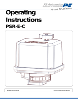
2.3. INTELLI+
INTELLI+ configurable control allows full actuator control including status reports, fault
processing, protections and command processing.
In addition, local controls can be locally disabled (padlock) or remotely (if BUS board is present).
The inverter switches are built into control compartment.
The INTELLI+ control allows non-intrusive configuration and settings. It includes a LCD display
and tools for preventive maintenance.

Invest in confidence
NR1214 EN - INTELLI+ SIL Manual ind. F - INTELLI+ SIL OMM
8
2.4. Safety Integrity Level (SIL)
In 1998, knowledge-sharing resulted in the publication of the series of standards IEC 61508
"Functional Safety of Electrical / Electronic / Programmable Electronic Safety-related Systems."
These standards introduce for the first time the concept of Safety Integrity Level (SIL).
The Safety Integrity Level (SIL) is a measure of the level of safety provided by a technical risk
management measure in an industrial environment.
SIL is qualified on a specific feature called Safety Instrumented Function (SIF) or on a safety
system gathering several instrumented safety functions. This is called "Safety Instrumented
System" (SIS). IEC 61511 standard specifically details SIS requirements.
Safety Expressions and Abbreviations
SIL
PFD
Probability of Failure on Demand
PFH
« Probability of dangerous Failure per Hour » :
probability of a dangerous random equipment failure per
hour
PFD
« Probability of Failure on Demand »
SIL
Safety Integrity Level
HFT
Hardware Fault Tolerance
Characteristic values
SIL
PFD
Probability of
Failure on
Demand
RRF
Risk Reduction Factor
PFH
Probability of
dangerous
Failure per Hour
1
10
-1
to 10
-2
10 to 100
10
-5
to 10
-6
2
10
-2
to 10
-3
100 to 1,000
10
-6
to 10
-7
3
10
-3
to 10
-4
1,000 to 10,000
10
-7
to 10
-8
4
10
-4
to 10
-5
10,000 à 100,000
10
-8
to 10
-9
RRF=1/PFD

Invest in confidence
NR1214 EN - INTELLI+ SIL Manual ind. F - INTELLI+ SIL OMM
9
Actuators of the Intelli+ SIL range are SIL2-certified (SIL3 in the case of a 1oo2 redundancy) for the
following safety features:
FS1: Position indication via relay (open valve, closed valve)
FS2 : Emergency Stayput (Emergency closing, Emergency stop and Opening
position according to configuration)
FS3: 4/20mA current loop proportional position signal
Upon detection of a fault that can alter security features, fault relays indicate the presence of
the fault. The list of faults and involved relays can be found in "SIL Functions" section.
The Intelli+ system is B-type with a 0 tolerance of hardware fault. The evaluation of the safety
integrity was performed by applying the 1h course from 61508-2 d standard. Complying to the
standard, an analysis of failure modes, of their effects and their cause (FMEDA) allowed to
calculate reliability data shown in the following table.
Function
description
Function
Demand
HFT
SD (FIT)
SU (FIT)
DD (FIT)
DU
(FIT)
SFF
(%)
PFD *
PFH
SIL
Level
Valve
status
FS1
strong
0
457.86
2452.89
9496.61
163.50
98.6
-
1,962E-07
2
ESD
opening
FS2
weak
0
457.86
6270.18
14392.96
160.61
99.2
4,455E-03
-
2
ESD closing
FS2
weak
0
457.86
6270.18
14392.96
160.61
99.2
4,455E-03
-
2
ESD
Stayput
FS2
weak
0
457.86
6270.18
14392.96
160.61
99.2
4,455E-03
-
2
Valve
position
FS3
strong
0
87.53
158.55
1121.14
127.58
91.6
-
1,927E-07
2
*PFH is valid for a year. For longer intervals between the maintenance interventions, please refer
to periodic audits section.

Invest in confidence
NR1214 EN - INTELLI+ SIL Manual ind. F - INTELLI+ SIL OMM
10
2.5. SIL requirements
SIL capability requires safety checks during installation and maintenance of our equipment. We
will call SIL requirements, requirements necessary to reach the desired SIL level. They will be
listed in a red box with a requirement number. User will imperatively have to follow them during
installation or maintenance of the device. Please find below a summary of the requirements
mentioned in the user manual.
In three-phase, it is essentiel to respect the direct order of the phases. If this order is not
observed, direction of rotation will be reversed and a SIL error will be indicated. In
addition, if you disconnect and reconnect a servomotor, it is compulsory to remake a SIL
validation (see §4.5.2) to check whether the rotation is in the expected direction, and
launch an ESD command to validate wiring.
-L1 on item 1 -L2 on item 2 -L3 on item 3
SIL requirement - EX_SEC_D202_0_14
Each modification must be followed by a check conducted by an qualified person. In case
the procedure fails, the system does not take into account the new setting but retains the
previous one.
SIL requirement - EX_SEC_D200_LOG11
A "SIL Error" is indicated via terminals 21 and 23. When no error is present, the contact
between these terminals is closed.
SIL Requirement - EX_SEC_AMDEC_4
The activity recorder must be kept, so if the board is replaced, the EEPROM must be
retrieved from the old main board. If the EEPROM is inoperative, the main board and the
contactors must be replaced.
SIL Requirement - EX_SEC_RV_20120110_1
Beyond 10,000 cycles, a maintenance operation must be carried out on the wheel/screw.
SIL Requirement - EX_SEC_AMDEC_MECA_1
User has to ensure that motor surface temperature (excluding motor heating) does not
exceed specified ambient temperature range. Measures provinding protection from heat
sources and special paints must be specified by the user according to the environment and
application.
SIL Requirement - EX_SEC_AMDEC_MECA_2

Invest in confidence
NR1214 EN - INTELLI+ SIL Manual ind. F - INTELLI+ SIL OMM
11
- Safety functions "Emergency close" ESD, "Emergency open" ESD and "Stayput" ESD fit in
this framework.
Bernard Controls demands a time interval shorter or equal to 2 years between 2
periodical tests of FS2 security function (ESD), to comply with the SIL2 level.
- User must comply with the frequency of checks specified for the complete loop of the
instrumented safety system in which the actuator will be integrated.
- Please find in the table below the evolution of PFD according to T1 checking interval:
Function
T1
PFD
ESD (FS2)
1 year
4,455E-03
ESD (FS2)
2 years
8,900E-03
ESD (FS2)
5 years
2.224E-02
ESD (FS2)
10 years
4.447E-02
SIL Requirement - EX_SEC_REG_20130726_1
User is responsible to ensure that valve is sized to handle torque in complete safety.
SIL Requirement - EX_SEC_AMDEC_MECA_3
F

Invest in confidence
NR1214 EN - INTELLI+ SIL Manual ind. F - INTELLI+ SIL OMM
12
2.6. MODELS PRESENTATION
The range of actuators offering a SIL capability is:
Explosion-proof version
- Multi-turn: STX6 to STX140 (built-in electronics)
explosion-proof ST175 and ST220 (built-in electronics)
- Quarter turn: SQX18 to SQX80 (built-in electronics)
- Control box: FPx casing with electronics, separate
Weatherproof version
- Multi-turn: ST6 to ST70 (electronics in adjacent FPi casing)
ST175 and ST220 (built-in electronics)
ASM0 to ASM3 (electronics in adjacent FPi casing)
- Quarter turn: SQ20 to SQ80 (electronics in adjacent FPi casing)
- Control box: FPi casing with electronics, separate
Actuator + reduction gear
Weatherproof and explosion-proof multi-turn actuators can be coupled to a gearbox.
F

Invest in confidence
NR1214 EN - INTELLI+ SIL Manual ind. F - INTELLI+ SIL OMM
13
2.7. Explosion-proof range
2.7.1. STX6 to STX140 (built-in electronics)
STX6
STX10-STX20
STX60-STX100
STX140
STX40

Invest in confidence
NR1214 EN - INTELLI+ SIL Manual ind. F - INTELLI+ SIL OMM
14
2.7.2. ST175 to ST220 ADF (built-in electronics)
2.7.3. SQX18 to SQX80 (built-in electronics)
2.7.4. FPx casing with electronics, separate
ST175-ST220 ADF
SQX18 to SQX80
FPX casing
F

Invest in confidence
NR1214 EN - INTELLI+ SIL Manual ind. F - INTELLI+ SIL OMM
15
2.8. Weatherproof range
2.8.1. ST6 to ST220 (electronics in adjacent FPi casing)
ST6
ST14
ST30
ST70
ST175-ST220

Invest in confidence
NR1214 EN - INTELLI+ SIL Manual ind. F - INTELLI+ SIL OMM
16
2.8.2. SQ20 to SQ80 (electronics in adjacent FPi casing)
2.8.3. ASM0 to ASM3 (electronics in adjacent FPi casing)
2.8.4. FPi casing with electronics, separate
SQ20 to SQ80
ASM0 to
ASM3
FPi casing

Invest in confidence
NR1214 EN - INTELLI+ SIL Manual ind. F - INTELLI+ SIL OMM
17
2.9. Actuators characteristics
2.9.1. Environmental characteristics
Ambient temperature: the actuators are designed to operate at an ambient
temperature between -20 °C to + 40 °C. Temporarily and depending on options, they
should be able to operate at -40 ° C and +70 ° C.
Severity: -20°C and optional - 40°C. Duration: 16h. This duration is due to the high
inertia of a servomotor.
Test according to the IEC 68-2-1 - Cold test
Dry test according to the IEC 68-2-2 - Heat test
Duty cycle:
Operation must be intermittent (S4 intermittent duty). Electric motors fitted to our servomotors
have a 30% duty cycle, which means that after each operation (opening and closing), downtime
of at least 2 or 3 times of the operating time must be observed. As duty cycle, ambient
temperature is relevant to determine the maximum number of starts/hour.
Ambient temperature
Starts/hour
-20°C to +40°C
360
-40°C to +60°C
190
-60°C to +68°C
155
Sealing: The minimum required tightness level is IP67. Tightness level is not intended
for the immersion of the actuators but to improve protection to moisture (see below).
A higher level could be chosen, for example 5 m/72 h or 10 m/ 96 h IP68 depending on
the type of actuator.
Severity: (see standard)
Test according to IEC 60529 - IP code
Wet heat: as electronics are not compatible with a wet atmosphere, it is required to
ensure that the casing provides adequate protection from moisture. Moisture could get
in the electronics compartment because of an effect of pump due to temperature
variations. Hot/wet cycles are carried out for this test.
Test according to IEC 68-2-3 - Continuous wet heat test
User has to ensure that motor surface temperature (excluding motor heating) does not
exceed specified ambient temperature range. Measures provinding protection from heat
sources and special paints must be specified by the user according to the environment and
application.
SIL Requirement - EX_SEC_AMDEC_MECA_2

Invest in confidence
NR1214 EN - INTELLI+ SIL Manual ind. F - INTELLI+ SIL OMM
18
Vibrations: As an actuator is mounted on a valve or a louver, vibrations can disturb the
its correct operation.
Test according to IEC 60068-2-6 - Sinusoidal vibrations
2g (19.6m/s²) from 10 to 500 Hz
Electromagnetic compatibility
For SIL safety, only immunity has to be taken in account.
Test according to IEC 61000-6-2 - Standard generic / Immunity for industrial environment
Lightning: See EN 61000-6-2 above which refers to EN 61000-4-5 - Shock waves (caused
by lightning).
The intense magnetic field test is not taken into account : only ILS are sensitive to it but without
affecting SIL functions.
Field of application
Actuator can operate in:
- On-Off: A class | S4-30% and S2-15mn
- Modulating class: Class III | S4-50%
Power supplies
SIL functions
Single phase
50 Hz or 60 Hz
Three-phase
50 Hz or 60 Hz
ESD STAYPUT
YES (diagram on
request)
YES
ESD OPEN
NO
YES
ESD CLOSE
NO
YES
SIGNALING RELAY
YES (diagram on
request)
YES
PROPORTIONAL SIGNALING
OPTION (4-20mA)
YES (diagram on
request)
YES
2.9.2. Devices
Backlit graphic display with choice of language
Power take-off with encoder
Torque limiter with sensor
Switching from one mode to another (manual - electric) is automatic without clutch lever (except
ST6/ASM). Electrical control has always priority on manual control.
One clutch handle for ST6 handwheel

Invest in confidence
NR1214 EN - INTELLI+ SIL Manual ind. F - INTELLI+ SIL OMM
19
2.9.3. Grease
ST+FPx and ST175/220 ADF range
- Grease > Shell GADUS S5 V142 00
or Shell TIVELA COMPOUND A : Operating temperature: -40°C to +68°C
- Grease > Total MARSON SY00: Operating temperature: -40°C to +68°C
STX6 to STX140 range
- Oil > CONDAT SY320: Operating temperature: -20°C to +68°C
- Huile > MOTUL GEAR 300: Operating temperature: -50°C to +68°C
«Low temperature»
- Grease > Imperator LIPRO EP2: Grease used for anti backing-off devices
ASM/SQ/SQX and STX6 range
- Grease > Total N31272: Operating temperature: -20°C to +68°C
- Grease > Condat GR40: Operating temperature: -50°C to +68°C
"Low temperature" Wheel and worm
- Grease > Fuchs Wynns VT800: Operating temperature: –50°C to 68°C
Grease film to use on primary reduction
2.9.4. Separate casing
The use of a separate FPi or FPx box type is possible provided that:
a maximum distance of 50m is observed
a control cable shielded with a copper braid and a minimum section of 0,5mm² is used
One grease cannot be mixed with another.
Important

Invest in confidence
NR1214 EN - INTELLI+ SIL Manual ind. F - INTELLI+ SIL OMM
20
2.10. REFERENCE DOCUMENTATION
Dimensional drawings: BERNARD CONTROLS
Model
Drawing numbers
Model
Drawing numbers
ST6
Z2201/00
STX6
Z1654/02
ST14
Z2206/00
STX10
Z1671/02
ST30
Z2211/00
STX20
Z1672/05
ST70
Z2216/00
STX40
Z1673/03
ST175
Z2221/00
STX60
Z1675/08
ST220
Z2226/00
STX100
Z1674/03
ASM0
Z2116/00
STX140
Z1681/00
ASM1
Z2116/00
ST175 Explosion-proof
Z2223/00
ASM2
Z2121/00
ST220 Explosion-proof
Z2228/00
ASM3
Z2121/00
SQX25
Z1684/00
SQ20
Z2153/00
SQX50
Z1654/05
SQ25
Z2154/00
SQX80
Z1682/00
SQ50
Z2156/00
FPX
Z2805/00
SQ80
Z2159/00
FPi
Z2800/00
Internal wiring diagram
Model
Drawing numbers
Standard diagram
On request according to the actuator
Test sheet and declaration of conformity:
A test sheet (IMP094 form) is supplied with each SIL device.
Following information is recorded on this test sheet:
Identification of the device
Check of the characteristics of the device
SIL parameters configuration
Test of the SIL configuration
Declaration of compliance with the IEC 61 508 standard
/