Page is loading ...

1) TURN OFF POWER.
IMPORTANT: Before you start, NEVER attempt any work
without shutting off the electricity until the work is done.
a) Go to the main fuse, or circuit breaker, box in your
home. Place the main power switch in the “OFF”
position.
b) Unscrew the fuse(s), or switch “OFF” the circuit breaker
switch(s), that control the power to the fixture or room
that you are working on.
c) Place the wall switch in the “OFF” position. If the fixture
to be replaced has a switch or pull chain, place those in
the “OFF” position.
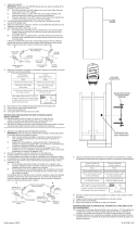
2) Find the appropriate threaded holes on mounting strap.
Assemble mounting screws into threaded holes.
3) Attach mounting strap to outlet box. (Screws not provided).
Mounting strap can be adjusted to suit position of fixture.
4) Grounding instructions: (See Illus. A or B).
A) On fixtures where mounting strap is provided with a hole
and two raise dimples. Wrap ground wire from outlet
box around green ground screw, and thread into hole.
B) On fixtures where a cupped washer is provided. Attach
ground wire from outlet box under cupped washer and
green ground screw, and thread into mounting strap.
If fixture is provided with ground wire. Connect fixture
ground wire to outlet box ground wire with wire connector.
(Not provided.) After following the above steps. Never connect
ground wire to black or white power supply wires.
5) Make wire connections (connectors not provided.) Reference
chart below for correct connections and wire accordingly.
6) Push fixture to wall, carefully passing mounting screws
through holes.
7) Screw threaded cap onto threaded pipe. Tighten threaded
cap to secure fixture to wall.
8) Insert recommended bulb.
9) Place diffuser up against fixture. Align holes in diffuser with
holes along edge of fixture.
10) Thread screws through holes in diffuser and into holes in
fixture. Tighten screws to secure diffuser in place.
11) Place faceplate up against fixture. Align holes in top and
bottom of faceplate with holes in top and bottom of fixture.
12) Thread screws through holes in faceplate and into holes in
fixture. Tighten screws to secure faceplate in to fixture.
Date Issued: 8/30/13 IS-6048-US
MOUNTING
STRAP
PLANCHA
PARA MONTAR
GREEN GROUND
SCREW
CUPPED
WASHER
A
B
OUTLET BOX
GROUND
FIXTURE
GROUND
DIMPLES
WIRE CONNECTOR
(NOT PROVIDED)
OUTLET BOX
GROUND
GREEN GROUND
SCREW
FIXTURE
GROUND
Connect Black or
Red Supply Wire to:
Connect
White Supply Wire to:
Black White
*Parallel cord (round & smooth) *Parallel cord (square & ridged)
Clear, Brown, Gold or Black
without tracer
Clear, Brown, Gold or Black
with tracer
Insulated wire (other than green)
with copper conductor
Insulated wire (other than green)
with silver conductor
*Note: When parallel wires (SPT I & SPT II)
are used. The neutral wire is square shaped
or ridged and the other wire will be round in
shape or smooth (see illus.)
Neutral Wire
THREADED
BALL
BOLA
ROSCADO
SCREW
TORNILLO
SCREW
TORNILLO
FACEPLATE
PLACA FRONTAL
DIFFUSER
DIFUSOR
FIXTURE
ARTEFACTO
We’re here to help 866-558-5706
Hrs: M-F 9am to 5pm EST
SEE OTHER SIDE FOR SPANISH TRANSLATIONS.
VEA EL OTRO LADO DE TRADUCCIONES AL ESPAÑOL.

1) TURN OFF POWER.
IMPORTANT: Before you start, NEVER attempt any work
without shutting off the electricity until the work is done.
a) Go to the main fuse, or circuit breaker, box in your
home. Place the main power switch in the “OFF”
position.
b) Unscrew the fuse(s), or switch “OFF” the circuit breaker
switch(s), that control the power to the fixture or room
that you are working on.
c) Place the wall switch in the “OFF” position. If the fixture
to be replaced has a switch or pull chain, place those in
the “OFF” position.
2) Find the appropriate threaded holes on mounting
strap. Assemble mounting screws into threaded holes.
3) Attach mounting strap to outlet box. (Screws not provided).
Mounting strap can be adjusted to suit position of fixture.
4) Make wire connections (connectors not provided.) Reference
chart below for correct connections and wire accordingly.
5) Push fixture to wall, carefully passing mounting screws
through holes.
6) Screw threaded cap onto threaded pipe. Tighten threaded
cap to secure fixture to wall.
7) Insert recommended bulb.
8) Place diffuser up against fixture. Align holes in diffuser with
holes along edge of fixture.
9) Thread screws through holes in diffuser and into holes in
fixture. Tighten screws to secure diffuser in place.
10) Place faceplate up against fixture. Align holes in top and
bottom of faceplate with holes in top and bottom of fixture.
11) Thread screws through holes in faceplate and into holes in
fixture. Tighten screws to secure faceplate in to fixture.
1) COUPER LE COURANT.
IMPORTANT: TOUJOURS couper l’électricité avant de
commencer le travail.
a) Localiser le coffret à fusibles ou le disjoncteur du
domicile. Mettre l’interrupteur principal en position
d’Arrêt.
b) Dévisser le ou les fusibles (ou mettre le disjoncteur sur
Arrêt) qui contrôlent l’alimentation vers le luminaire ou la
pièce dans laquelle le travail est effectué.
c) Mettre l’interrupteur mural en position d’Arrêt. Si le luminaire
à remplacer est doté d’un interrupteur ou d’une chaîne
connectée à l‘interrupteur, placer ces éléments en
position d’Arrêt.
2) Trouver les trous filetés appropriés sur la barrette de montage.
Vissez les vis de montage dans les trous filetés.
3) Visser la barrette de montage à la boite de jonction. (Vis
non fournies). La barrette de montage peut etre ajustée pour
convenir à la position de l’applique.
4) Connecter les fils (connecteurs non fournis). Se reporter au
tableau ci-dessous pour faire les connexions.
5) Plaquez l’applique contre le mur, en passant soigneusement
les vis de montage dans les trous.
Connect Black or
Red Supply Wire to:
Connect
White Supply Wire to:
Black White
*Parallel cord (round & smooth) *Parallel cord (square & ridged)
Clear, Brown, Gold or Black
without tracer
Clear, Brown, Gold or Black
with tracer
Insulated wire (other than green)
with copper conductor
Insulated wire (other than green)
with silver conductor
*Note: When parallel wires (SPT I & SPT II)
are used. The neutral wire is square shaped
or ridged and the other wire will be round in
shape or smooth (see illus.)
Neutral Wire
Date Issued: 8/30/13 IS-6048-CB
INSTRUCTIONS
For Assembling and Installing Fixtures in Canada
Pour L’assemblage et L’installation Au Canada
THREADED BALL
BOULE FILETE
MOUNTING
STRAP
COLLLIER DE
FIXATION
Connecter le fil noir ou
rouge de la boite
Connecter le fil blanc de la boîte
A Noir A Blanc
*Au cordon parallèle (rond et lisse)
*Au cordon parallele (à angles droits el strié)
Au bransparent, doré, marron, ou
noir sans fil distinctif
Au transparent, doré, marron, ou
noir avec un til distinctif
Fil isolé (sauf fil vert) avec
conducteur en cuivre
Fil isolé (sauf fil vert) avec
conducteur en argent
*Remarque: Avec emploi d’un fil paralléle
(SPT I et SPT II). Le fil neutre est á angles
droits ou strié et l’autre fil doit étre rond ou
lisse (Voir le schéma).
Fil Neutre
6) Visser le bouchon fileté sur le tube fileté. Serrer le bouchon
fileté pour fixer le luminaire au mur.
7) Introduire l’ampoule recommandée.
8) Placer le diffuseur contre le luminaire Aligner les trous situés
dans le diffuseur aux trous le long du bord du luminaire.
9) Serrer les vis par les trous dans le diffuseur et dans ceux du
luminaire. Serrer les vis pour fixer le diffuseur.
10) Placer la plaque frontale contre le luminaire. Aligner les trous
situés en haut et en bas de la plaque frontale aux trous en
haut et en bas du luminaire.
11) Serrer les vis par les trous dans la plaque frontale et dans
les trous du luminaire. Serrer les vis pour fixer la plaque
frontale dans le luminaire.
FACEPLATE
PLAQUE FRONTALE
DIFFUSER
DIFFUSEUR
FIXTURE
LUMINAIRE
SCREW
VIS
SCREW
VIS
We’re here to help 866-558-5706
Hrs: M-F 9am to 5pm EST
/