Page is loading ...

Date Issued 10/23/98
IS-15671-US
INSTALLATION
1) Atornille una tuerca hexagonal en cada perno en "J" hasta que la
tuerca hexagonal llegue al extremo de las roscas.
2) Resbale los pernos en "J" a través de los agujeros pequeños en la
plantilla y asegure en su lugar utilizando arandelas y tuercas hexag-
onales.
3) Resbale el conjunto de plantilla/perno en "J" sobre el cable/conduc-
to a través de los agujeros grandes en la plantilla para asegurar la
colocación y la alineación. Quite el conjunto de la plantilla/perno en
"J".
4) Vacíe concreto en el agujero. NOTA: Asegúrese de que las longi-
tudes del alambre/conducto sean como se especifica.
5) Embeber los pernos en "J" en el concreto hasta que la parte inferior
de la plantilla siente en la parte superior del concreto y el cable/con-
ducto pase a través de los agujeros grandes en la plantilla.
120V Systems: All 120V installations should comply with local electrical
codes for fixture mounting and wiring methods. If you have any doubts con-
cerning installation contact a qualified licensed electrician.
12V Systems: Fixture is not to be installed within 10 feet (3m) of a pool, spa
or fountain.
Before starting: The following items should be completed before proceeding.
A) All holes should be dug. Holes should be at least 18” (457 mm)
deep by 8” (203 mm) diameter or to local code specifications.
B) All trenches should be dug for power supply.
120V: Reference local code specification
12V: Low voltage wiring is intended for shallow burial.
Do not bury deeper than 6” (152 mm) below surface.
C) Run Power supply conduit or cable.
120V: Conduit should protrude 2” (51mm) above top of
concrete and 6” (152 mm) of wire should protrude
from conduit.
12V: Cable should extend 7” (178 mm) above top of
concrete, and can be looped back down to run to
next fixture.
INSTALLATION
1) Screw one hexnut onto each “J” bolt until hexnut gets to end of
threads.
2) Slip “J” bolts through small holes in template and secure in place using
washers and hexnuts.
3) Slip “J” bolt/template assembly over conduit/cable through large holes
in template to insure placement and alignment. Remove “J” bolt/tem-
plate assembly.
4) Pour concrete into hole. NOTE: Make sure conduit/wire lengths remain
as specified.
5) Embed “J” bolts in concrete until bottom of template sits on top of con-
crete and conduit/cable passes through large holes in template.
6) Level template and allow concrete to cure. NOTE: Do not let wire fall
into wet concrete.
7) Remove template. It may be necessary to pry template away from con-
crete.
8) Proceed to instructions provided with bollard.
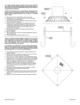
HEXNUT
TUERCA HEXAGONAL
J-BOLT
PERNO EN J
TEMPLATE
PLANTILLA
WASHER
ARANDELA
Sistemas de 120 V: Todas las instalaciones de 120 voltios deben cumplir con
los códigos eléctricos locales para montaje de artefactos y métodos de
cableado. Si tiene alguna duda referente a la instalación, comuníquese con
un electricista capaz licenciado.
Sistemas de 12 V: El artefacto no debe instalarse a menos de 10 pies (3 met-
ros) de distancia de una piscina (alberca), manantial de agua mineral (spa) o
fuente.
Antes de empezar: Los siguientes pasos deben completarse antes de pros-
eguir:
A) Todos los agujeros deben excavarse. Los agujeros deben ser por lo
menos de 18" (457 mm.) de profundidad por 8" (203 mm.) de
diámetro o de acuerdo con las especificaciones del código local.
B) Todas las zanjas deben excavarse para la alimentación eléctrica.
120V: Refiérase a la especificación del código local.
12V: El cableado de bajo voltaje está preparado para que
esté enterrado poco profundo. No entierre a una pro-
fundidad mayor que 6" (152 mm.) debajo de la super-
ficie.
C) Instale el cable o conducto de alimentación eléctrica.
120V: El conducto debe sobresalir 2" (51 mm.) por encima
de la parte superior del concreto y 6" (152 mm.) de
cable deben sobresalir del conducto.
12V: El cable debe extenderse 7" (178 mm.) por encima de
la parte superior del concreto, y puede conectarse en
serie hacia abajo para conectar al siguiente artefacto.
WARRANTY
WE WARRANT THE LANDSCAPE PRODUCTS FEATURED IN OUR LANDSCAPE LIGHTING CATALOG (WITH THE EXCEPTION OF LIGHT BULBS) FOR FIVE YEARS AGAINST
DEFECTS IN MATERIALS AND WORKMANSHIP IF IT WAS PROPERLY INSTALLED AND FAILED UNDER NORMAL OPERATING CONDITIONS, PROVIDED IT IS RETURNED TO THE
POINT OF PURCHASE, WHERE IT WILL BE REPAIRED OR, AS IT MAY BE DETERMINED, TO REPLACE THE LANDSCAPE PRODUCT OR PARTS USED ON THAT PRODUCT.
GARANTIA
NOSOTROS GARANTIZAMOS POR CINCO ANOS LOS PRODUCTOS PANORAMICOS QUE OFRECEMOS EN NUESTRO CATALOGO DE ILUMINACION PANORAMICA (CON EXCEPCION
DE LAS BOMBILLAS), QUE ESTAN EXENTOS DE DEFECTOS DE MATERIALES Y MANO DE OBRA, SI SE INSTALARON CORRECTAMIENTE Y FALLARON EN CONDICIONES DE
OPERACION NORMAL, SIEMPRE QUE SE DEVUELVAN AL LUGAR DE COMPRA, DONDE SERAN REPARADOS O, SEGUN PUEDA DETERMINARSE, SERAN CAMBIADOS LOS PRO-
DUCTOS PANORAMICOS O LAS PIEZAS UTILIZADAS EN ESE PRODUCTO
/


