
vacon
®
20 cp/x
ac drives
multipurpose application
manual


vacon • 0
Service support: find your nearest Vacon service center at www.vacon.com
INDEX
Document ID: DPD00536H
Order code: DOC-APP03982+DLUK
Rev. H
Version release date: 26.1.15
Corresponds to application package ACIT1075V111.vcx
1. Multipurpose Application................................................................................. 2
1.1 Specific functions of Vacon Multipurpose application...................................................... 2
1.2 Example of control connections ....................................................................................... 3
1.3 Optional boards ................................................................................................................. 5
1.3.1 Option board installation................................................................................................... 8
2. Description of Groups .................................................................................... 12
2.1 Keypad Reference: Menu REF ........................................................................................ 12
2.2 Monitor group: menu MON ............................................................................................. 13
2.3 Parameter Groups: Menu PAR ....................................................................................... 14
2.3.1 Group Basic Parameters: Menu PAR G1 ........................................................................ 15
2.3.2 Group Advanced Settings: Menu PAR G2........................................................................ 16
2.3.3 Group Analogue inputs: Menu PAR G3 ........................................................................... 18
2.3.4 Group Digital inputs: Menu PAR G4 ................................................................................ 19
2.3.5 Group Digital outputs: Menu PAR G5.............................................................................. 21
2.3.6 Group Analogue outputs: Menu PAR G6 ......................................................................... 22
2.3.7 Group Supervisions: Menu PAR G7................................................................................. 23
2.3.8 Group Motor Control: Menu PAR G8............................................................................... 24
2.3.9 Group Protections: Menu PAR G9................................................................................... 26
2.3.10 Group Autoreset: Menu PAR G10.................................................................................... 29
2.3.11 Group Fieldbus: Menu PAR G11...................................................................................... 30
2.3.12 Group PID-controller: Menu Par G12 ............................................................................. 31
2.3.13 Group temperature measurement: Menu Par G13 ........................................................ 32
2.4 System parameters, Faults and History faults: Menu SYS/FLT..................................... 33
3. Parameter description................................................................................... 36
3.1 Basic Parameters............................................................................................................ 36
3.2 Advanced settings ........................................................................................................... 37
3.3 Analogue inputs............................................................................................................... 46
3.4 Digital inputs ................................................................................................................... 50
3.5 Digital outputs ................................................................................................................. 52
3.6 Analogue Output..............................................................................................................54
3.7 Supervisions .................................................................................................................... 55
3.8 Motor control................................................................................................................... 57
3.9 Protections ...................................................................................................................... 61
3.10 Autoreset ......................................................................................................................... 67
3.11 Fieldbus ........................................................................................................................... 69
3.11.1 Fieldbus mapping............................................................................................................ 70
3.12 PID Control ...................................................................................................................... 73
3.13 Temperature measurement ........................................................................................... 75
4. Fault tracing .................................................................................................. 78

vacon • 1

Multipurpose Application vacon • 2
Service support: find your nearest Vacon service center at www.vacon.com
1
1. MULTIPURPOSE APPLICATION
The VACON
®
20 CP/X drive contains a preloaded application for instant use.
The parameters of this application are listed in chapter 2.3 of this manual and explained in
more detail in chapter 2.
1.1 Specific functions of Vacon Multipurpose application
The Vacon Multipurpose allows flexible use of VACON
®
20 CP/X frequency converters.
Features
The drive can be controlled through I/O terminals, a fieldbus or the optional keypad.Two pro-
grammable control places and sources for the frequency reference are available, for easy lo-
cal/remote control.
Frequency reference can be direct (analogue input, preset speeds, motor potentiometer, field-
bus) or controlled by the internal PID regulator.
PID setpoint and actual value are totally programmable. A "sleep" function is available, with
possibility of pressure boost and check of the losses before entering the stand-by state.
All the functionalities can be controlled through a fieldbus.
The motor identification function allows automatic optimization of the voltage/frequency curve,
for a optimal torque response also at low motor speed.
It is possible to install one optional board for I/O or fieldbus expansion.
Both AC induction motor and PM motor can be controlled.

vacon • 3 Multipurpose Application
1
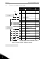
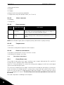
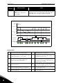
1.2 Example of control connections
Table 1. Connection example, standard I/O terminals.
Standard I/O terminals
Terminal Signal Default
A
RS485 Serial bus, negative
B
RS485 Serial bus, positive
1
+10 Vref Reference output
2
AI1+
Analogue input,
voltage or current
*
*
Selectable with DIP switches, see VACON
®
20 CP/X
Installation Manual
Voltage
3
AI1-/GND
Analogue input common
(current)
6
24Vout 24V aux. voltage
7
DIN COM Digital input common
8
DI1 Digital input 1 Start FWD
9
DI2 Digital input 2 Start REV
10
DI3 Digital input 3
Preset
Speed B0
4
AI2+
Analogue input,
voltage or current*
Current
5
AI2-/GND
Analogue input common
(current)
13
DO1- Digital Output Common
14
DI4 Digital input 4
Preset
Speed B1
15
DI5 Digital input 5
Fault
reset
16
DI6 Digital input 6 Ramp 2
18
AO1+ Analogue signal (+output)
Output
frequency
20
DO1+ Digital output +
Ready
Reference potentiometer
1...10 kΩ
V
To Relay terminals
1 or 2
PID Actual value
4...20mA/0...10V
(programmable)
X1

Multipurpose Application vacon • 4
Service support: find your nearest Vacon service center at www.vacon.com
1
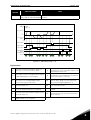
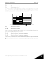
Table 2. Connection example, Relay terminals
Relay terminals
Default
Terminal Signal
22 RO1/2 CM
Relay output 1 RUN
23 RO1/3 NO
24 RO1/1 NC
Relay output 1 FAULT
25 RO1/2 CM
26 RO1/3 NO
From
Standard I/O terminals
From term.
#3 or #5
From term.
#6
FAULT

vacon • 5 Multipurpose Application
1
1.3 Optional boards
One optional I/O expansion board can be installed into the slot on the right side of the drive. The
following boards are supported:
OPTB1: 6 Digital Inputs-Outputs
The first 3 terminals are reserved as digital inputs (DI7, DI8, DI9). The second 3 terminals can
be used as inputs (DI10, DI11, DI12) or digital outputs (EO1, EO2, EO3). The number of terminals
used as input must be declared in parameter P2.24 (hidden if the board is not installed). This
number determines the higher value for the selection of the digital input connected to a certain
logical function. It also changes the visibility of parameters for the selection of digital outputs
function (P5.9, P5.10, P5.11).
OPTB2: 1 Thermistor Input, 2 Relays Outputs
Response to thermistor fault can be programmed with parameter P9.16. Relays functions can
be programmed with parameters P5.9, P5.10 (hidden if the board is not installed).
OPTB4: 1 Analogue Input, 2 Analogue Outputs
One more input is available as frequency reference. Signal programmable with parameters
P3.9 - 12. Two more outputs are available to monitor motor/drive signals. Outputs are pro-
grammable with parameters P6.5 - 12.
Parameters are hidden if the board is not installed.
OPTB5: 3 Relays Outputs
Relays functions can be programmed with parameters P5.9, P5.10, P5.11 (hidden if the board
is not installed).
OPTB9: 5 Digital Inputs, 1 Relay Output
The higher value for the selection of the digital input (DI7, DI8, DI9, DI10, DI11) connected to a
certain logical function is set to 11. Relay functions can be programmed with parameter P5.9
(hidden if the board is not installed).
OPTBF: 1 Analogue Output, 1 Digital Output, 1 Relay Output
The analogue output can be programmed with parameters P6.5 - 8. The digital output can be
programmed with parameter P5.12. The relay output can be programmed with parameter
P5.9. Parameters are hidden if the board is not installed.
OPTBH: 3 temperature sensors
When the board is installed, the specific menu G13 is visible. Temperature measurement can
be used to set a digital/relay output and/or to trigger a fault. It can also be used as direct fre-
quency reference or as actual value for PID regulation.
OPTBK: 4 ASi Outputs, 4 ASi Inputs
ASi outputs are managed as 4 optional digital inputs (DI7, DI8, DI9, DI10). The higher value for
the selection of the digital input connected to a certain logical function is set to 10.
ASi inputs 1-4 are managed as 4 optional outputs (EO1, EO2, EO3, EO4) programmable with
P5.9 - 12.
ASi inputs 1-3 are managed as 3 optional relay outputs (programmable with P5.9 - 11).

Multipurpose Application vacon • 6
Service support: find your nearest Vacon service center at www.vacon.com
1
ASi input 4 is managed as optional digital output (programmable with P5.12).
OPTC3/E3: Profibus DPV1 fieldbus board
Vacon 20CP/X frequency converters can be connected to the PROFIBUS DP network using a
fieldbus board. The converter can then be controlled, monitored and programmed from the
Host system.OPTE3 option board also supports connection from DP Master (class 2) if DP-V1
is enabled. In this case, the Master class 2 can initiate a connection, read and write parameters
using the PROFIdrive Parameter Access service, and close the connection. The PROFIBUS DP
fieldbus is connected to the OPTE3 board using a 5-pin pluggable bus connector. The only dif-
ference between OPTE3 and OPTE5 boards is the fieldbus connector.
OPTC4 Lonworks fieldbus board
Vacon 20CP/X frequency converters can be connected to the LonWorks® network using a
fieldbus board. The converter can then be controlled, monitored and programmed from the
Host system.
OPTC5/E5: Profibus DPV1 fieldbus board (D-type connector)
Vacon 20CP/X frequency converters can be connected to the PROFIBUS DP network using a
fieldbus board. The converter can then be controlled, monitored and programmed from the
Host system.OPTE5 option board also supports connection from DP Master (class 2) if DP-V1
is enabled. In this case, the Master class 2 can initiate a connection, read and write parameters
using the PROFIdrive Parameter Access service, and close the connection. he PROFIBUS DP
fieldbus is connected to the OPTE5 board using a 9-pin female sub-D-connector. The only dif-
ference between OPTE3 and OPTE5 boards is the fieldbus connector.
OPTC6/E6: CanOpen fieldbus board
Vacon 20CP/X frequency converters can be connected to the CanOpen system using a fieldbus
board. The converter can then be controlled, monitored and programmed from the Host sys-
tem. Vacon CanOpen Board is connected to the fieldbus through a 5-pin pluggable bus connec-
tor (board NXOPTE6).
OPTC7/E7: DeviceNet fieldbus board
Vacon 20CP/X frequency converters can be connected to the DeviceNet using a fieldbus board.
The converter can then be controlled, monitored and programmed from the Host system. Va-
con DeviceNet Board is connected to the fieldbus through a 5-pin pluggable bus connector
(board OPTE7).
OPTCI: Modbus TCP fieldbus board
Vacon 20CP/X frequency converters can be connected to Ethernet using an Ethernet fieldbus
board OPTCI. Every appliance connected to an Ethernet network has two identifiers; a MAC ad-
dress and an IP address. The MAC address (Address format: xx:xx:xx:xx:xx:xx ) is unique to the
appliance and cannot be changed. The Ethernet board's MAC address can be found on the
sticker attached to the board or by using the Vacon IP tool software NCIPConfig. Please find
the software installation at www.vacon.com. In a local network, IP addresses can be defined by
the user as long as all units connected to the network are given the same network portion of
the address. For more information about IP addresses, contact your Network Administrator.
Overlapping IP addresses cause conflicts between appliances.

vacon • 7 Multipurpose Application
1
OPTCP: Profinet fieldbus board
Vacon 20CP/X frequency converters can be connected to Ethernet using an Ethernet fieldbus
board OPTCP. Every appliance connected to an Ethernet network has two identifiers; a MAC
address and an IP address. The MAC address (Address format: xx:xx:xx:xx:xx:xx) is unique to
the appliance and cannot be changed. The Ethernet board's MAC address can be found on the
sticker attached to the board or by using the Vacon IP tool software NCIPConfig. You can find
the software installation at www.vacon.com. In a local network, IP addresses can be defined by
the user as long as all units connected to the network are given the same network portion of
the address. For more information about IP addresses, contact your Network Administrator.
Overlapping IP addresses cause conflicts between appliances.
OPTCQ: Ethernet IP fieldbus board
Vacon 20CP/X frequency converters can be connected to Ethernet using an EtherNet/IP field-
bus board OPT-CQ. Every appliance connected to an Ethernet network has two identifiers; a
MAC address and an IP address. The MAC address (Address format: xx:xx:xx:xx:xx:xx) is
unique to the appliance and cannot be changed. The EtherNet/IP board's MAC address can be
found on the sticker attached to the board or by using the Vacon IP tool software NCIPConfig.
Please find the software installation at www.vacon.com. In a local network, IP addresses can
be defined by the user as long as all units connected to the network are given the same network
portion of the address. For more information about IP addresses, contact your Network Ad-
ministrator. Overlapping IP addresses cause conflicts between appliances.

Multipurpose Application vacon • 8
Service support: find your nearest Vacon service center at www.vacon.com
1
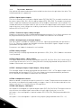
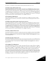
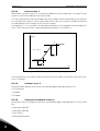
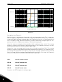
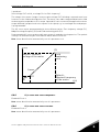
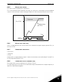
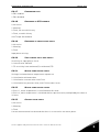
1.3.1 Option board installation
Figure 1. Opening the main cover, MU3 example.
NOTE! It is not allowed to add or replace option boards or fieldbus boards on an AC
drive with the power switched on. This may damage the boards.
1
• Open the cover of the drive.
The relay outputs and other I/O-terminals may have a dangerous control voltage
present even when the drive is disconnected from mains.
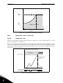
2
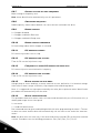
• Remove the option slot cover.

vacon • 9 Multipurpose Application
1
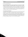
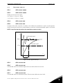
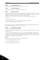
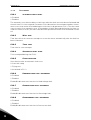
Figure 2. Removing the option slot cover.
3
• Make sure that the sticker on the connector of the board says “dv” (dual
voltage). This indicates that the board is compatible with Vacon 20CP/X.
See below:
• NOTE: Incompatible boards cannot be installed on Vacon 20CP/X. Compat-
ible boards have a slot coding that enable the placing of the board (see
above).
Slot coding
OPT
dv
9116.emf

Multipurpose Application vacon • 10
Service support: find your nearest Vacon service center at www.vacon.com
1
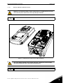
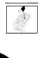
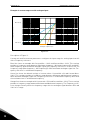
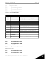
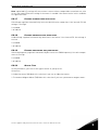
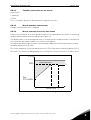
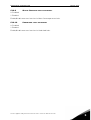
Figure 3. Option board installation.
4
• Install the option board into the slot as shown in the picture below.
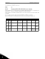
5
• Mount the option slot cover.

vacon • 11 Multipurpose Application
1
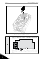
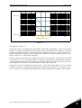
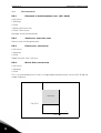
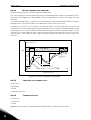
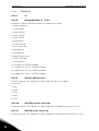
Figure 4. Mounting of option slot cover: remove the plastic opening for option board termi-
nals.

Description of Groups vacon • 12
Service support: find your nearest Vacon service center at www.vacon.com
2
2. DESCRIPTION OF GROUPS
2.1 Keypad Reference: Menu REF
This menu is automatically entered when pressing the LOC/REM keypad and shows the fre-
quency reference in Local control mode.
The reference is also active when selected as main reference (P1.12=4) or as secondary refer-
ence (P2.15=4).
Value is limited between min frequency P1.1 and max frequency P1.2.
In Local mode, or when keypad is the active control place (P1.11=1 or P2.14=1), direction of ro-
tation is determined with P2.23 or by pressing the left or right arrow button: this functionality
could be blocked by setting P2.27=1.

vacon • 13 Description of Groups
2
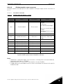
2.2 Monitor group: menu MON
VACON
®
20 CP/X AC drive provides you with a possibility to monitor the actual values of pa-
rameters and signals as well as statuses and measurements. See Table in which the basic
monitoring values are presented.
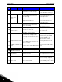
Code Monitoring value Unit ID Description
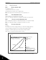
V1.1 Output frequency Hz 1 Output frequency to motor
V1.2 Frequency reference Hz 25 Frequency reference to motor control
V1.3 Motor shaft speed rpm 2 Motor speed in rpm
V1.4 Motor Current A 3
V1.5 Motor Torque % 4 Calculated shaft torque
V1.6 Motor Power % 5 Total power consumption of AC drive
V1.7 Motor Voltage V 6
V1.8 Motor temperature % 9 Calculated motor temperature
V1.9 DC-link Voltage V 7
V1.10 Unit temperature °C 8 Heatsink temperature
V1.11 Board temperature °C 1825 Power board temperature
V1.12 Analogue input 1 % 13 Analogue input AI1
V1.13 Analogue input 2 % 14 Analogue input AI2
V1.14 Exp. Analogue input % 1837 Analogue input on OPTB4
V1.15 Analogue output % 26 Analogue output
V1.16 Exp. Analogue out 1 % 1838 Analogue output 1 on OPTB4-BF
V1.17 Exp. Analogue out 2 % 1839 Analogue output 2 on OPTB4
V1.18 DI1, DI2, DI3 15 Digital inputs status
V1.19 DI4, DI5, DI6 16 Digital inputs status
V1.20 DI7, DI8, DI9 1835 Digital inputs on OPTB1 status
V1.21 DI10, DI11, DI12 1836 Digital inputs on OPTB1 status
V1.22 RO1, RO2, DO 17 Digital outputs status
V1.23 EO1, EO2, EO3, EO4 1852 Expansion board digital outputs status
V1.24 Process variable 29 Scaled process variable. See P7.10
V1.25 PID setpoint % 20 PID controller setpoint
V1.26 PID error value % 22 PID controller error
V1.27 PID feedback % 21 PID controller actual value
V1.28 PID output % 23 PID controller output
V1.29 Temperature sensor 1 °C or °K 1860 OPTBH sensor 1
V1.30 Temperature sensor 2 °C or °K 1861 OPTBH sensor 2
V1.31 Temperature sensor 3 °C or °K 1862 OPTBH sensor 3
V1.32 ASi board state 1894 OPTBK state
Table 3: Monitoring menu items.
NOTE!
Values V1.25-28 are hidden when PID output is not used as frequency reference.
Values V1.14, V1.17 are hidden when OPTB4 expansion board is not installed.
Value V1.16 is hidden when OPTB4-BF expansion board is not installed.
Values V1.20, V1.21 are hidden when no expansion board with available inputs is installed. Value
V1.23 is hidden when no expansion board with available outputs is installed.
Values V1.29, V1.30, V1.31 are hidden when OPTBH expansion board is not installed.
Value V1.32 is hidden when OPTBK expansion board is not installed.

Description of Groups vacon • 14
Service support: find your nearest Vacon service center at www.vacon.com
2
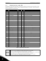
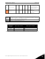
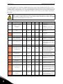
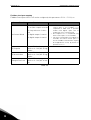
2.3 Parameter Groups: Menu PAR
The Multipurpose Application embodies the following parameter groups:
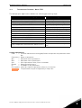
Column explanations:
Code = Location indication on the keypad; Shows the operator the parameter num-
ber.
Parameter= Name of parameter
Min = Minimum value of parameter
Max = Maximum value of parameter
Unit = Unit of parameter value; Given if available
Default = Value preset by factory
ID = ID number of the parameter
Description= Short description of parameter values or its function
= The parameter may be changed only in Stop state
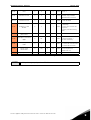
Menu and Parameter group Description
Group Basic Parameters: Menu PAR G1 Basic settings
Group Advanced Settings: Menu PAR G2 Advanced parameter settings
Group Analogue inputs: Menu PAR G3 Analogue input programming
Group Digital inputs: Menu PAR G4 Digital input programming
Group Digital outputs: Menu PAR G5 Digital output programming
Group Analogue outputs: Menu PAR G6 Analogue outputs programming
Group Supervisions: Menu PAR G7 Prohibit frequencies programming
Group Motor Control: Menu PAR G8 Motor control and U/f parameters
Group Protections: Menu PAR G9 Protections configuration
Group Autoreset: Menu PAR G10 Auto reset after fault configuration
Group Fieldbus: Menu PAR G11 Fieldbus data out parameters
Group PID-controller: Menu Par G12 Parameters for PID Controller.
Group Temperature measurement: Menu Par G13
Temperature measurement parame-
ters.
Table 4. Parameter groups.

vacon • 15 Description of Groups
2
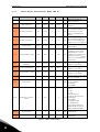
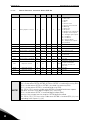
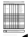
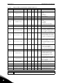
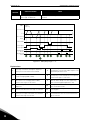
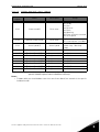
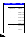
2.3.1 Group Basic Parameters: Menu PAR G1
Code Parameter Min Max Unit Default ID Description
P1.1 Min frequency 0.00 P1.2 Hz 0.00 101
Minimum allowed fre-
quency reference
P1.2 Max frequency P1.1 320.00 Hz 50.00 102
Maximum allowed frequency
reference
P1.3 Acceleration time 1 0.1 3000.0 s 3.0 103
Defines the time required
for the output frequency to
increase from zero fre-
quency to maximum fre-
quency
P1.4 Deceleration time 1 0.1 3000.0 s 3.0 104
Defines the time required
for the output frequency to
decrease from maximum
frequency to zero frequency
P1.5 Current limit
0.2 x I
H
2 x I
H
A
I
H
107
Maximum motor current
from AC drive
P1.6 Motor nominal voltage 180 500 V 400 110
Find this value U
n
on the
rating plate of the motor.
This parameter sets the
voltage at the field weaken-
ing point to 100% * U
nMotor
.
Note also used connection
(Delta/Star).
P1.7
Motor nominal
frequency
8.00 320.00 Hz 50.00 111
Find this value f
n
on the rat-
ing plate of the motor.
P1.8 Motor nominal speed 24 20000 rpm 1440 112
Find this value n
n
on the rat-
ing plate of the motor.
P1.9 Motor nominal current
0.2 x I
H
2 x I
H
A
I
H
113
Find this value I
n
on the rat-
ing plate of the motor.
P1.10 Motor Cos ϕ 0.30 1.00 0.85 120
Find this value on the rating
plate of the motor
P1.11 Control Place 0 2 0 125
Run and direction control:
0 = I/O terminals
1 = Keypad
2 = Fieldbus
P1.12
Frequency reference
source
0 5-7* 0 1819
Selection of reference
source:
0 = AI1
1 = AI2
2 = PID reference
3 = Motor potentiometer
4 = Keypad
5 = Fieldbus
6 = Expansion AI1
7 = Temperature
(*)6 requires expansion
board OPTB4; 7 requires
expansion board OPTBH.
P1.13 Start function 0 1 0 505
0=Ramping
1=Flying start
P1.14 Stop function 0 1 0 506
0=Coasting
1=Ramping
Table 5. Basic parameters.

Description of Groups vacon • 16
Service support: find your nearest Vacon service center at www.vacon.com
2
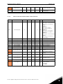
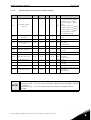
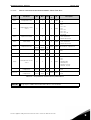
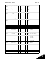
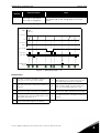
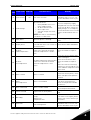
2.3.2 Group Advanced Settings: Menu PAR G2
P1.15 Torque boost 0 1 0 109
0 = Not active
1 = Auto torque boost
P1.16 Show all parameters 0 1 0 115
0 = only Basic
1 = All groups
Code Parameter Min Max Unit Default ID Description
P2.1 Start/Stop logic 0 3 0 300
Logic = 0:
Start sign 1 = Start Forward
Start sign 2 = Start Back-
ward
Logic =1:
Start sign 1 = Start
Start sign 2 = Reverse
Logic = 2:
Start sign 1 = Start pulse
Start sign 2 = Stop pulse
Logic = 3:
Start sign 1 = Start Forward
(edge)
Start sign 2 = Start Back-
ward (edge)
P2.2 Preset speed 1 0.00 P1.2 Hz 10.00 105 Multistep speed 1
P2.3 Preset speed 2 0.00 P1.2 Hz 15.00 106 Multistep speed 2
P2.4 Preset speed 3 0.00 P1.2 Hz 20.00 126 Multistep speed 3
P2.5 Preset speed 4 0.00 P1.2 Hz 25.00 127 Multistep speed 4
P2.6 Preset speed 5 0.00 P1.2 Hz 30.00 128 Multistep speed 5
P2.7 Preset speed 6 0.00 P1.2 Hz 40.00 129 Multistep speed 6
P2.8 Preset speed 7 0.00 P1.2 Hz 50.00 130 Multistep speed 7
P2.9 Acceleration time 2 0.1 3000.0 s 10.0 502
Time from 0 to max fre-
quency
P2.10 Deceleration time 2 0.1 3000.0 s 10.0 503
Time from 0 to max fre-
quency
P2.11
Accel1 to Accel2 tran-
sition frequency
0.00 P1.2 Hz 0.00 527
Threshold for auto change
from acc1 to acc2
P2.12
Decel1 to Decel2 tran-
sition frequency
0.00 P1.2 Hz 0.00 528
Threshold for auto change
from dec2 to dec1
P2.13 S ramp shape 1 0.0 10.0 s 0.0 500 Rounded speed profile.
P2.14
Control place 2
0 2 0 1806
Alternative control place:
0: I/O terminals
1: Keypad
2: Fieldbus
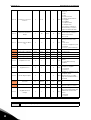
Table 6. Advanced settings group.
Table 5. Basic parameters.

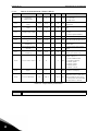
vacon • 17 Description of Groups
2
P2.15
Frequency reference
source 2
0 5-7* 1 1820
Selection of reference
source 2:
0 = AI1
1 = AI2
2 = PID reference
3 = Motor potentiometer
4 = Keypad
5 = Fieldbus
6 = Expansion AI1
7 = Temperature
(*)6 requires expansion
board OPTB4; 7 requires
expansion board OPTBH.
P2.16
MotorPotentiometer
Ramp
1 50 Hz/s 5 331
Rate of change in the motor
potentiometer reference
when increased or
decreased.
P2.17
MotorPotent Ref Mem-
ory
0 2 0 367
Motor potentiometer fre-
quency reference reset
logic.
0 = No reset
1 = Reset if stopped or pow-
ered down
2 = Reset if powered down
P2.18 Skip range 1 low lim 0.00 P1.2 Hz 0.00 509 0 = Not used
P2.19 Skip range 1 high lim 0.00 P1.2 Hz 0.00 510 0 = Not used
P2.20 Skip range 2 low lim 0.00 P1.2 Hz 0.00 511 0 = Not used
P2.21 Skip range 2 high lim 0.00 P1.2 Hz 0.00 512 0 = Not used
P2.22 Stop button active 0 1 1 114
0 = Limited function of Stop
button
1 = Stop button always
enabled
P2.23 Keypad Reverse 0 1 0 123
Motor rotation when con-
trol place is keypad
0 = Forward
1 = Reverse
P2.24 OPTB1 Digital inputs 3 6 6 1829
Number of terminals used
as digital inputs.
The parameter is visible
only when OPTB1 board is
installed
P2.25
Quick Stop decelera-
tion time
0.1 3000.0 s 2.0 1889
Time from max frequency to
0
P2.26 S ramp shape 2 0.0 10.0 s 0.0 501
Rounded speed profile
when Acc/Dec 2 is active.
P2.27
Keypad direction
change
0 1 0 1897
Allow to change motor
direction using keypad LEFT
and RIGHT arrow in REF
menu
0: Allowed
1: Locked
NOTE!
Visibility of the group depends on P1.16.
Table 6. Advanced settings group.
Page is loading ...
Page is loading ...
Page is loading ...
Page is loading ...
Page is loading ...
Page is loading ...
Page is loading ...
Page is loading ...
Page is loading ...
Page is loading ...
Page is loading ...
Page is loading ...
Page is loading ...
Page is loading ...
Page is loading ...
Page is loading ...
Page is loading ...
Page is loading ...
Page is loading ...
Page is loading ...
Page is loading ...
Page is loading ...
Page is loading ...
Page is loading ...
Page is loading ...
Page is loading ...
Page is loading ...
Page is loading ...
Page is loading ...
Page is loading ...
Page is loading ...
Page is loading ...
Page is loading ...
Page is loading ...
Page is loading ...
Page is loading ...
Page is loading ...
Page is loading ...
Page is loading ...
Page is loading ...
Page is loading ...
Page is loading ...
Page is loading ...
Page is loading ...
Page is loading ...
Page is loading ...
Page is loading ...
Page is loading ...
Page is loading ...
Page is loading ...
Page is loading ...
Page is loading ...
Page is loading ...
Page is loading ...
Page is loading ...
Page is loading ...
Page is loading ...
Page is loading ...
Page is loading ...
Page is loading ...
Page is loading ...
Page is loading ...
Page is loading ...
Page is loading ...
Page is loading ...
Page is loading ...
Page is loading ...
Page is loading ...
-
 1
1
-
 2
2
-
 3
3
-
 4
4
-
 5
5
-
 6
6
-
 7
7
-
 8
8
-
 9
9
-
 10
10
-
 11
11
-
 12
12
-
 13
13
-
 14
14
-
 15
15
-
 16
16
-
 17
17
-
 18
18
-
 19
19
-
 20
20
-
 21
21
-
 22
22
-
 23
23
-
 24
24
-
 25
25
-
 26
26
-
 27
27
-
 28
28
-
 29
29
-
 30
30
-
 31
31
-
 32
32
-
 33
33
-
 34
34
-
 35
35
-
 36
36
-
 37
37
-
 38
38
-
 39
39
-
 40
40
-
 41
41
-
 42
42
-
 43
43
-
 44
44
-
 45
45
-
 46
46
-
 47
47
-
 48
48
-
 49
49
-
 50
50
-
 51
51
-
 52
52
-
 53
53
-
 54
54
-
 55
55
-
 56
56
-
 57
57
-
 58
58
-
 59
59
-
 60
60
-
 61
61
-
 62
62
-
 63
63
-
 64
64
-
 65
65
-
 66
66
-
 67
67
-
 68
68
-
 69
69
-
 70
70
-
 71
71
-
 72
72
-
 73
73
-
 74
74
-
 75
75
-
 76
76
-
 77
77
-
 78
78
-
 79
79
-
 80
80
-
 81
81
-
 82
82
-
 83
83
-
 84
84
-
 85
85
-
 86
86
-
 87
87
-
 88
88


Ask a question and I''ll find the answer in the document
Finding information in a document is now easier with AI
Related papers
Other documents
-
Vacon 20 CP/X Applications Manual
-
Vacon 20 X Operating instructions
-
-
Vacon 20 Quick Manual
-
-
-
 Austdac HBTX4A Installation guide
-
-
-
