Page is loading ...

GP-2A
Earth Ground Tester
Users Manual
• Manualdeuso

English
GP-2A
Earth Ground Tester
UsersManual
GP-2A_Rev002
©2012AmprobeTestTools.
Allrightsreserved.

Limited Warranty and Limitation of Liability
YourAmprobeproductwillbefreefromdefectsinmaterialandworkmanshipfor1yearfrom
thedateofpurchase.Thiswarrantydoesnotcoverfuses,disposablebatteriesordamagefrom
accident,neglect,misuse,alteration,contamination,orabnormalconditionsofoperationor
handling.Amprobe’swarrantyobligationislimited,atAmprobe’soption,torefundofthe
purchaseprice,freeofchargerepair,orreplacementofadefectiveproduct.Resellersarenot
authorizedtoextendanyotherwarrantyonAmprobe’sbehalf.Toobtainserviceduringthe
warrantyperiod,returntheproductwithproofofpurchasetoanauthorizedAmprobeTest
ToolsServiceCenterortoanAmprobedealerordistributor.SeeRepairSectionfordetails.This
warrantyisyouronlyremedy.Allotherwarranties-whetherexpress,impliedorstatutory-
includingimpliedwarrantiesoftnessforaparticularpurposeormerchantability,arehereby
excluded.NeitherAmprobenoritsparentcompanyorafliatesshallbeliableforanyspecial,
indirect,incidentalorconsequentialdamagesorlosses,arisingfromanycauseortheory.Since
somestatesorcountriesdonotallowtheexclusionorlimitationofanimpliedwarrantyorof
incidentalorconsequentialdamages,thislimitationofliabilitymaynotapplytoyou.
Repair
Alltesttoolsreturnedforwarrantyornon-warrantyrepairorforcalibrationshouldbe
accompaniedbythefollowing:yourname,company’sname,address,telephonenumber,and
proofofpurchase.Additionally,pleaseincludeabriefdescriptionoftheproblemortheservice
requestedandincludethetestleadswiththemeter.Non-warrantyrepairorreplacement
chargesshouldberemittedintheformofacheck,amoneyorder,creditcardwithexpiration
date,orapurchaseordermadepayabletoAmprobe®TestTools.
In-Warranty Repairs and Replacement – All Countries
Pleasereadthewarrantystatementandcheckyourbatterybeforerequestingrepair.Duringthe
warrantyperiodanydefectivetesttoolcanbereturnedtoyourAmprobe®TestToolsdistributor
foranexchangeforthesameorlikeproduct.Pleasecheckthe“WheretoBuy”sectiononwww.
amprobe.comforalistofdistributorsnearyou.Additionally,intheUnitedStatesandCanadaIn-
WarrantyrepairandreplacementunitscanalsobesenttoaAmprobe®TestToolsServiceCenter
(seebelowforaddress).
Non-Warranty Repairs and Replacement – US and Canada
Non-warrantyrepairsintheUnitedStatesandCanadashouldbesenttoaAmprobe®TestTools
ServiceCenter.CallAmprobe®TestToolsorinquireatyourpointofpurchaseforcurrentrepair
andreplacementrates.
InUSA InCanada
AmprobeTestTools AmprobeTestTools
Everett,WA98203 Mississauga,ONL4Z1X9
Tel:888-993-5853 Tel:905-890-7600
Fax:425-446-6390 Fax:905-890-6866
Non-Warranty Repairs and Replacement – Europe
Europeannon-warrantyunitscanbereplacedbyyourAmprobe®TestToolsdistributorfora
nominalcharge.Pleasecheckthe“WheretoBuy”sectiononwww.amprobe.comforalistof
distributorsnearyou.
EuropeanCorrespondenceAddress*
Amprobe®TestToolsEurope
Beha-AmprobeGmbH
IndenEngematten14
79286Glottertal,Germany
Tel.:+49(0)76848009–0
*(Correspondenceonly–norepairorreplacementavailablefromthisaddress.European
customerspleasecontactyourdistributor.)

1
GP-2A Earth Ground Tester
CONTENTS
1. SAFETY PRECAUTIONS AND PROCEDURES.................................................................................... 2
1.1Preliminaryinstructions............................................................................................................. 2
1.2Duringuse.................................................................................................................................. 3
1.3Afteruse...................................................................................................................................... 3
1.4Denitionofmeasurementcategory(Overvoltage)............................................................... 3
2. GENERAL DESCRIPTION................................................................................................................... 4
2.1Instrumentdescription............................................................................................................... 4
3. PREPARING THE INSTRUMENT......................................................................................................... 4
3.1Initialcheck................................................................................................................................. 4
3.2Powersupply.............................................................................................................................. 4
3.3Calibration.................................................................................................................................. 4
3.4Storage........................................................................................................................................ 4
4. WORKING INSTRUCTIONS............................................................................................................... 5
4.1Instrumentdescription............................................................................................................... 5
4.2Measuringaccessoriesdescription............................................................................................ 6
4.2.1Switchingon...................................................................................................................... 6
4.2.2Autopoweroff................................................................................................................. 6
4.3EARTH3W–Threewireearthresistancemeasurement......................................................... 7
4.4EARTH2W–Twowireearthresistancemeasurement............................................................ 9
4.5
r
-Groundresistivitymeasurement........................................................................................ 11
4.5.1Anomalousmeasuringapplications–allmodes........................................................... 14
5. MANAGEMENT OF STORED DATA................................................................................................ 17
5.1Howtosaveameasurement................................................................................................... 17
5.2Howtocanceloneorseveralmeasurements......................................................................... 17
5.3Howtorecallameasurement................................................................................................. 18
6.INSTRUMENT RESET AND DEFAULT PARAMETERS....................................................................... 19
7. NSTRUMENT CONNECTION TO PC................................................................................................ 19
8. MAINTENANCE............................................................................................................................... 20
8.1General..................................................................................................................................... 20
8.2Batteryreplacement................................................................................................................ 20
8.3Instrumentcleaning................................................................................................................. 20
8.4Endoflife................................................................................................................................. 20
9. TECHNICAL SPECIFICATIONS.......................................................................................................... 21
9.1Denitions................................................................................................................................ 21
9.2Technicalfeatures.................................................................................................................... 22
9.2.1Safetystandards.............................................................................................................. 23
9.2.2Generalfeatures.............................................................................................................. 23
9.3Environment............................................................................................................................. 23
9.3.1Operatingenvironmentalconditions............................................................................ 23
9.3.2EMC.................................................................................................................................. 23
10. PRACTICAL REPORTS FOR ELECTRICAL TESTS............................................................................ 24
10.1Earthresistanceinttsystems................................................................................................. 24
10.2Earthresistance,voltaamperemetricmethod...................................................................... 24
10.2.1Creatingcablesextensions......................................................................................... 24
10.2.2Methodforsmall-sizedearthrods............................................................................. 25
10.2.3Methodforlarge-sizedearthrods............................................................................. 25
10.3Groundresistivity................................................................................................................... 26
10.3.1Approximateevaluationofintentionalrods’contribution..................................... 27

2
1. SAFETY PRECAUTIONS AND PROCEDURES
TheinstrumentwasdesignedincompliancewithstandardsEN61557andEN61010-1relativeto
electronicequipment.
�CAUTION
Foryourownsafetyandtoavoiddamagingtheinstrumentyouarerecommendedtofollow
theproceduresdescribedinthismanualandreadcarefullyallinstructionsprecededbythis
symbol�
Beforeandduringmeasurementskeeptothefollowinginstructions:
•Donottakemeasurementsinwetplacesaswellasinthepresenceofexplosivegasand
combustiblesorindustyplaces.
•Eventhoughyouarenottakinganymeasurementavoidanycontactwiththecircuitunder
test,withexposedmetalparts,unusedmeasuringterminals,circuitsetc.
•Donottakeanymeasurementanymeasurementwheneveranomalousconditionsoccursuch
asdeformations,breaks,leakages,blinddisplayetc.
•Payutmostattentionwhentakingmeasurementsofvoltagehigherthan25Vinspecial
places(buildingyards,swimmingpools,etc.)andhigherthan50Vinordinaryplacesdueto
theriskofelectricshock.
Thefollowingsymbolsareusedinthismanualaswellasontheinstrument:
�
CAUTION: Please read carefully this manual in order to understand the nature of the
potential danger and the actions to undertake
Refertotheinstructionmanual.Animproperusemaydamagetheinstrumentorits
componentsaswellasendangertheuser
D
DCorACvoltageandcurrent
X
Highvoltagedanger:riskofelectricshock
T
Doubleinsulation
=
Thebarredsymboloftherubbishbinshownontheequipmentindicatesthat,atthe
endofitsusefullife,boththeproductsanditsaccessoriesshallbecollectedseparately
fromotherwasteandcorrectlydisposed
1.1 Preliminary Instructions
•Thisinstrumentwasdesignedforuseinenvironmentswithpollutiondegree2.
•Itcanbeusedforvoltageandcurrentmeasurementsonelectricalinstallationswithover
voltagecategoryIII240Vtoearthandmaximumvoltageof415Vbetweeninputs.
•Youarerecommendedtorespecttheusualsafetyregulationsaimedatprotectingyou
againstdangerouscurrentsandtheinstrumentagainstimproperuse.
•Onlytheoriginalaccessoriessuppliedalongwiththeinstrumentguaranteecompliancewith
thesafetystandardsinforce.Theymustbeinagoodconditionand,ifnecessary,replaced
withidenticalones.
•Donottestnorconnecttoanycircuitexceedingthespeciedoverloadprotection.
•Donottakemeasurementsunderenvironmentalconditionsexceedingthelimitsindicatedin
thismanual.
•Makesurethatbatteriesarecorrectlyinstalled.
•Beforeconnectingtestleadstothecircuitundertestcheckthattherightfunctionwas
selected.

3
1.2 During Use
Youarerecommendedtoreadcarefullythefollowinginstructions:
�CAUTION
Failuretocomplywithwarningsandinstructionsmaydamagetheinstrumentand/orits
componentsaswellasinjuretheoperator
Ifthelowbatterysymbolisdisplayedduringuseinterrupttestingandreplacebatteries
followingtheproceduredescribedinparagraph8.2
•Beforeselectinganewfunctiondisconnectthetestleadsfromthecircuitundertest.
•Whentheinstrumentisconnectedtothecircuitundertestnevertouchanyunusedterminal.
•Donotmeasureresistanceinthepresenceofexternalvoltages;althoughtheinstrumentis
protected,anexcessivevoltagemaycausemalfunction.
•Avoidsubmittingtheinstrumenttovoltagewhilemeasuring(i.e.atestleadslippingoffthe
measuringpointaccidentallytouchinganenergizedpoint).UnpackingAndInspection
1.3 After Use
•TurnofftheinstrumentpressingON/OFFkeyafterusingit.
•Ifyouexpectnottousetheinstrumentforalongtimeremovethebatteries.
1.4 Definition Of Measurement Category (Overvoltage)
ThestandardsEN61010-1:Safetyrequirementsforelectricalequipmentformeasurement,
controlandlaboratoryuse,Part1:Generalrequirements,denewhatameasurementcategory,
usuallycalledovervoltagecategory,means.Underparagraph6.7.4:Measuringcircuits,itquotes:
Circuitsaredividedintothefollowingmeasurementcategories:
•MeasurementcategoryIVisformeasurementsperformedatthesourceofalow-voltage
installation.
•Examplesareelectricitymetersandmeasurementsonprimaryexcesscurrentprotection
devicesaswellasripplecontrolunits.MeasurementcategoryIIIisformeasurements
performedinthebuildinginstallations.
•Examplesaremeasurementsondistributionboards,circuitbreakers,wiring,includingcables,
bus-bars,junctionboxes,switches,socket-outletsinthexedinstallations,andequipment
forindustrialuseaswellassomeotherequipment,forexample,stationarymotorswith
permanentconnectiontoxedinstallations.MeasurementcategoryIIisformeasurements
performedoncircuitsdirectlyconnectedtothelowvoltageinstallations.
•Examplesaremeasurementsonhouseholdappliances,portabletoolsandsimilarequipment.
MeasurementcategoryIisformeasurementsperformedoncircuitsnotdirectlyconnectedto
MAINS.
•ExamplesaremeasurementsoncircuitsnotderivedfromMAINS,andspecially(internally)
protectedMAINS-derivedcircuits.Inthislattercase,transientstressesarevariable;forthis
reason,thenormrequiresthatthetransientwithstandingcapabilityoftheequipmentis
madeknowntotheuser.

4
2. GENERAL DESCRIPTION
Thisinstrumentwillgrantyouaccurateandreliablemeasurementsprovidedthatisused
accordingtotheinstructionsgiveninthismanual.Youwillenjoythehighestsafetythankstoa
developmentofnewestconceptionassuringdoubleinsulationandovervoltagecategoryIII.
2.1 Instrument Description
•EARTH2W:two-wireearthresistancemeasurement.
•EARTH3W:three-wireearthresistancemeasurement.
• r:four-wiregroundresistivitymeasurement.
3. PREPARING THE INSTRUMENT
3.1 Initial Check
Thisinstrumentwascheckedbothmechanicallyandelectricallypriortoshipment.Allpossible
caresandprecautionsweretakentoletyoureceivetheinstrumentunderperfectconditions.
Notwithstandingwesuggestyoutocheckitrapidlytocheckanydamagewhichmayhave
occurredduringtransport.Shoulditbethecasepleasecontactimmediatelytheforwarderor
yourdealer.
Yourshippingcartonshouldinclude:
1 GP-2A
4 Groundstakes
1 Testleadset(banana–banana)
1 Alligatorclipset
1 OpticalUSBcable
1 USBdriverCD
1 Carryingcase
1 User’smanual
Ifanyoftheitemsaredamagedormissing,returnthecompletepackageto
theplaceofpurchaseforanexchange.
3.2 Power Supply
Theinstrumentispoweredbybatteries(refertoparagraph9.2.2forfurtherdetailsonmodel,
numberandbatterylife).Thebatterychargeisdisplayedontherighttopside.Thesymbol
indicatesthatbatteriesarefullycharged,whilethesymbol indicatesthatbatteriesarelow
andshallbereplaced.
Toreplace/insertbatteriesfollowtheinstructionsindicatedunderparagraph8.2.
3.3 Calibration
Theinstrumentcomplieswiththetechnicalspecicationsreportedinthismanualandsucha
complianceIsguaranteedforoneyearafterpurchasedate.
3.4 Storage
Afteraperiodofstorageunderextremeenvironmentalconditionsexceedingthelimitslet
theinstrumentresumenormalmeasuringconditionsbeforeusingit(seeenvironmental
specicationslistedunderparagraph9.3.1).Thisprecautionwillgrantaccuratemeasurements
withoutriskingtodamagetheinstrument.

5
4. WORKING INSTRUCTIONS
4.1 Instrument Description
1
8
2
3
4
6
7
5
1
Inputs
2
ENTER / Arrow keys
ENTER keytoselectmeasuringmode
Arrowkeystomovethecursorselectingtherequiredparameters
3
Back light key / ESC
Back light keytoturnonthedisplaybacklightfor30seconds
ESC keytoquitwithoutselectinganymode
4
RCL / CLR key
RCL keytorecalldatastoredintheinstrument’smemory
CLR keytocanceltheselectedmeasurementsfromtheinstrument’smemory
5
Display
6
GO keytostartameasurement
7
SAVE keytostoremeasurements
8
ON/OFF keytoturnon/offtheinstrument

6
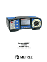
4.2 Measuring Accessories Description
1
2
2
2
Fig.1
4.2.1 Switching on
Whenswitchingontheinstrumentabrieftoneisaudiblealongwithdisplayofallsegmentsfor
aboutonesecond.
Subsequentlythelastrmwareversionaswellasthelastselectedmeasuringmodearedisplayed
beforeswitchingoff.
4.2.2 Auto power off
Theinstrumentautomaticallyturnsoff3minutesafterthelastkeypressing.Toresume
operationturnontheinstrumentpressingtheon/offkey.
1
Barrier
2
Hand-Held Area

7
4.3 EARTH 3W – Three Wire Earth Resistance Measurement
ThemeasurementiscarriedoutincompliancewithstandardsIEC781,VDE0413,EN61557-5.
�CAUTION
•Theinstrumentcanbeusedforvoltageandcurrentmeasurementsoninstallationswith
overvoltagecategoryCATIII240Vtoearthandmaximumvoltageof415Vbetweeninputs.
Donotconnecttheinstrumenttoinstallationswhosevoltagesexceedthelimitsindicated
inthismanual.Exceedingsuchlimitsmaycauseelectricshocktotheuseranddamagethe
instrument
•Alwaysconnectthecablestotheinstrumentandtothealligatorclipswhenthelatterare
notconnectedtotheplantundertest
•AlwaysrespecttheHand-heldareaofprobe(see4.2)
•Ifthelengthofthesuppliedcablesisn’tsuitablefortheplantundertest(seePar.11),You
cancreateyourownextensionsfollowingindicationsinPar.11.2.1
Fig.2:Three-wireearthresistancemeasurement
1.
TurnontheinstrumentpressingtheON/OFFkey
2.
Pressingright/leftarrowkeys , selectMOD,thenpressingup/downarrow
keys , select3Woption
3. Ascreensimilartotheonebelowappearswheretheinputinterferingvoltagevalueof
theinstrumentisdisplayed
(Inputinterferingvoltagevalue)
4. Connecttheblue,red,greenandblackcablestothecorrespondinginstrument’sinput
terminalsH,S,ES,Ethenaddingcrocodilesifnecessary
5. Extend,ifnecessary,theblueandredmeasuringcablesseparatelyusingcableswith
propersection.Addinganyextensiondoesnotrequirecalibrationanddoesnotaffect
themeasuredearthresistancevalue
6. Drivetheauxiliaryrodsintothegroundkeepingtothedistanceinstructionsprovidedby
thestandards(§11.2)
7. Connectcrocodilestotheauxiliaryrodsandtotheinstallationundertest(seeFig.2)

8
8. PressGOkey,theinstrumentstartscarryingoutmeasurement
9. Whiletheinstrumentismeasuringascreensimilartotheonebelowappearswherethe
instrument’sinputinterferingvoltagevalueisdisplayed.Whenthemessage
isdisplayeddonotdisconnectortouchthetestleads
(Inputinterferingvoltagevalue)
�CAUTION
Whenstartingmeasurementtheinputinterferingvoltageismeasuredatboththevoltand
amperecircuit.Shoulditrangebetween3Vand9V,theinstrumentcarriesoutmeasurement
anddisplaysthesymbol�indicatingtheuncertaintydeclineofthemeasurement(§9.1)
10. Whenthetestisover,shouldtheearthresistancevaluebelowerthanthefullscale,the
instrumentemitsadoubletoneindicatingthepositiveoutcomeofthetestanddisplays
theresistancemeasurementaswellastheinterferingvoltagevalueatthetimeof
measuring
(Inputinterferingvoltagevalue)
�CAUTION
Theresistancemeasurementiseffectedwith4-wirevoltamperemethodwithoutbeing
affectedbytheresistancevalueofthecables.Itisthereforenotnecessarytoeffect
compensationofcableresistanceorofanyextension
11. Whenthetestisover,shouldtheearthresistancevaluebehigherthanthefullscale,the
instrumentemitsalongtoneindicatingthenegativeoutcomeofthetestanddisplays
thescreenbelow
(Inputinterferingvoltagevalue)
12.
ThemeasurementscanbestoredpressingtheSAVEkeytwice(§5.1)
(Earthresistancemeasurement)
(Earthresistancemeasurementhigherthanfullscale)

9
4.4 EARTH 2W – Two Wire Earth Resistance Measurement
�CAUTION
•Theinstrumentcanbeusedforvoltageandcurrentmeasurementsoninstallationswith
overvoltagecategoryequaltoCATIII240Vtoearthandmaximumvoltageof415Vbetween
inputs.Donotconnecttheinstrumenttoinstallationswhosevoltagesexceedthelimits
indicatedinthismanual.Exceedingsuchlimitsmaycauseelectricshocktotheuserand
damagetheinstrument
•Alwaysconnectthecablestotheinstrumentandtothealligatorclipswhenthelatterare
notconnectedtotheplantundertest
•AlwaysrespecttheHand-heldareaofprobe(see4.2)
•Ifthelengthofthesuppliedcablesisn’tsuitablefortheplantundertest(seePar.11),You
cancreateyourownextensionsfollowingindicationsinPar.11.2.1
Wheneveritisnotpossibletodriverodsintothegroundtotakeathree-wiremeasurement(i.e.
historicalcentres),itispossibletousethesimpliedtwo-wiremethodwhichgivesanexcess
valueforthesakeofsafety.Tocarryoutthetestasuitableauxiliaryrodisnecessary;anauxiliary
rodisdeemedassuitablewhenitsearthresistanceisnegligibleandindependentoftheearth
installationundertest.
InFig.3alamppostisusedasauxiliaryrod,howeveranymetalbodydrivenintothegroundcan
beusedprovidedthattheabovementionedrequirementsaremet.
�CAUTION
TheinstrumentdisplaysthesumvalueofRA+RTasresult(seeFig.3andFig.4).Therefore
themeasurementachievedistheclosertoRA(prospectivevalue)themorenegligibleisthe
valueRToftheauxiliaryrodwithrespecttoRAitself.Inadditionthemeasurementwillbe
increased“forsafetysake”byRT,i.e.ifRA+RTresultstobecoordinatedwithprotective
conductors,RAalonewillbefarmorecoordinated
Fig.3:Two-wireearthresistancemeasurementusinganauxiliaryrod
IntheTTsystems(seeFig.4)itispossibletoperformatwo-wireearthmeasurementusingthe
NEUTRALconductorprovidedbythenationalEnergyBoardtakendirectlyfromasocketorpanel
boardasanauxiliaryrod;ifalsotheearthconnectionisavailable,themeasurementcanbe
takenonthesocketdirectly,betweenNEUTRALandEARTH.
�CAUTION
Ifyouwishtoeffectthemeasurementusingtheneutralandearthconductorsofanordinary
socket,youmayaccidentallyconnecttophase;inthiscasethedetectedvoltageaswellasthe
warningsymbol
forwrongenteringwillbedisplayedandnomeasurementwillbeeffectedeventhoughthe
GOkeyispressed.

10
Fig.4:Two-wireearthresistancemeasurementfromthepanelboard
1.
TurnontheinstrumentpressingtheON/OFFkey
2.
Pressingright/leftarrowkeys , selectMOD,thenpressingup/downarrow
keys , select2Woption
3. Ascreensimilartotheonebelowappearswheretheinputinterferingvoltagevalueof
theinstrumentisdisplayed
(Inputinterferingvoltagevalue)
4. Connecttheblue,red,greenandblackcablestothecorrespondinginstrument’sinput
terminalsH,S,ES,Ethenaddingcrocodilesifnecessary
5. Extend,ifnecessary,theblueandredmeasuringcablesseparatelyusingcableswith
propersection.Addinganyextensiondoesnotrequirecalibrationanddoesnotaffect
themeasuredearthresistancevalue
6. Connectcrocodilestotheauxiliaryrodsandtotheinstallationundertest(seeFig.3and
Fig.4)
7.
PressGOkey,theinstrumentstartscarryingoutmeasurement
8. Whiletheinstrumentismeasuringascreensimilartotheonebelowappearswherethe
instrument’sinputinterferingvoltagevalueisdisplayed.Whenthemessage
isdisplayeddonotdisconnectortouchthetestleads
(Inputinterferingvoltagevalue)

11
�CAUTION
Whenstartingmeasurementtheinputinterferingvoltageismeasuredatboththevoltand
amperecircuit.Shoulditrangebetween3Vand9V,theinstrumentcarriesoutmeasurement
anddisplaysthesymbol�indicatingtheuncertaintydeclineofthemeasurement(§9.1)
9. Whenthetestisover,shouldtheearthresistancevaluebelowerthanthefullscale,the
instrumentemitsadoubletoneindicatingthepositiveoutcomeofthetestanddisplays
theresistancemeasurementaswellastheinterferingvoltagevalueatthetimeof
measuring
(Inputinterferingvoltagevalue)
�CAUTION
Theresistancemeasurementiseffectedwith4-wirevoltamperemethodwithoutbeing
affectedbytheresistancevalueofthecables.Itisthereforenotnecessarytoeffect
compensationofcableresistanceorofanyextension
10. Whenthetestisover,shouldtheearthresistancevaluebehigherthanthefullscale,the
instrumentemitsalongtoneindicatingthenegativeoutcomeofthetestanddisplays
thescreenbelow
(Inputinterferingvoltagevalue)
11.
ThemeasurementscanbestoredpressingtheSAVEkeytwice(§5.1)
4.5
r
- Ground Resistivity Measurement
Thegroundresistivityvalueisanessentialparametertocalculatetheresistancevalueofthe
earthrodstobeusedfortheearthinstallation’sconstruction.Themeasurementiseffected
accordingtostandardsIEC781,VDE0413EN61557-5.
�CAUTION
•Theinstrumentcanbeusedforvoltageandcurrentmeasurementsoninstallationswith
overvoltagecategoryequaltoCATIII240Vtoearthandmaximumvoltageof415Vbetween
inputs.Donotconnecttheinstrumenttoinstallationswhosevoltagesexceedthelimits
indicatedinthismanual.Exceedingsuchlimitsmaycauseelectricshocktotheuserand
damagetheinstrument
•Alwaysconnectthecablestotheinstrumentandtothealligatorclipswhenthelatterare
notconnectedtotheplantundertest
•AlwaysrespecttheHand-heldareaofprobe(see4.2)
•Ifthelengthofthesuppliedcablesisn’tsuitablefortheplantundertest(seePar.11),You
cancreateyourownextensionsfollowingindicationsinPar.11.2.1
(Earthresistancemeasurement)
(Earthresistancemeasurementhigherthanfullscale)

12
Fig.5:Groundresistivitymeasurement
1.
TurnontheinstrumentpressingtheON/OFFkey
2.
Pressingright/leftarrowkeys , selectMOD,thenpressingup/downarrow
keys , selectoption
3. Ascreensimilartotheonebelowappearswhereboththeinputinterferingvoltageof
theinstrumentandtherods’distancevaluearedisplayed
(Valueofinputinterferingvoltageandrods’distanceset)
4. Shouldyouneedtomodifytherods’distancepressthearrowkeys , and
selectDIST,thenpressingthearrowkeys , setthedesireddistance(ranging
from1upto10metres,bystepsofoneorfrom3upto30feetbystepsofthree)
(Valueofrods’distanceset)
5.
Tosetthedistancemeasuringunitpressthearrowkeys , andselectUNIT,

13
thenpressingthearrowkeys , setthedesiredmeasuringunit(morft)
(Measuringunitselected)
6. Connecttheblue,red,greenandblackcablestothecorrespondinginstrument’sinput
terminalsH,S,ES,Ethenaddingcrocodilesifnecessary
7. Extend,ifnecessary,theblueandredmeasuringcablesseparatelyusingcableswith
propersection.Addinganyextensiondoesnotrequirecalibrationanddoesnotaffect
themeasuredgroundresistivityvalue
8. Drivetheauxiliaryrodsintothegroundplacingthemonalineatamutualdistance
equaltothatselectedontheinstrument.Settingadistanceotherthantheactual
distancebetweentheearthrodsmayaffectthemeasurement(§11.3)
9. Connectcrocodilestotheauxiliaryrods(seeFig.5)
10.
PressGOkey,theinstrumentstartscarryingoutmeasurement
11. Whiletheinstrumentismeasuringascreensimilartotheonebelowappearswherethe
instrument’sinputinterferingvoltagevalueandthedistancesetbetweenauxiliaryrods
aredisplayed.Whenthemessageis
displayeddonotdisconnectortouchthe
testleads
(Valueofinputinterferingvoltageandrods’distanceset)
�CAUTION
Whenstartingmeasurementtheinputinterferingvoltageismeasuredatboththevoltand
amperecircuit.Shoulditrangebetween3Vand9V,theinstrumentcarriesoutmeasurement
anddisplaysthesymbol�indicatingtheuncertaintydeclineofthemeasurement(§9.1)
12. Whenthetestisover,shouldthegroundresistivityvaluebelowerthanthefullscale,
theinstrumentemitsadoubletoneindicatingthepositiveoutcomeofthetestand
displaystheresistivitymeasurementaswellastheinterferingvoltagevalueatthetime
ofmeasuring
(Valueofinputinterferingvoltageandrods’distanceset)
(Measurementofgroundresistivity)

14
�CAUTION
Theresistivitymeasurementiseffectedwith4-wirevoltamperemethodwithoutbeing
affectedbytheresistancevalueofthecables.Itisthereforenotnecessarytoeffect
compensationofcableresistanceorofanyextension.
13. Whenthetestisover,shouldthegroundresistivityvaluebehigherthanthefullscale,
theinstrumentemitsalongtoneindicatingthenegativeoutcomeofthetestand
displaysthescreenbelow
(Valueofinputinterferingvoltageandrods’distanceset)
�CAUTION
ThefullscaleiscalculatedasPMAX=2DISTRwhereDISTisthevaluesetforthedistance
amongtherodsandRthemaximumresistancevaluewhichcanbemeasuredbythe
instrument.Thefullscaleofgroundresistivitymeasurementdependsonthesettingofthe
distanceamongtherods
14.
ThemeasurementscanbestoredpressingtheSAVEkeytwice(§5.1)
4.5.1 Anomalous measuring applications – all modes
1. Whenstartingameasurementtheinstrumentchecksthecontinuityofmeasuringcables.
Ifthevoltcircuit(redcableSandgreencableES)isinterruptedoritsresistancevalueis
toohigh,theinstrumentdisplaysascreensimilartotheonebelow.Checkthatterminals
areproperlyconnectedandthattheearthrodisconnectedtoterminalSandnotdriven
intoapebblyorscarcelyconductiveground.Inthislattercasepourwateraroundthe
rodtodecreaseitsresistancevalue(§11.2).
RP>topisdisplayedwhen:
TheSrod’sresistanceRS>50KΩissummeduptothevoltcircuit
TheresistanceofrodSexceedsthevalue1200+100RX[Ω](whereRXistheearth
resistancevalue)
(Examplefor3Wmode)
2. Whenstartingameasurementtheinstrumentchecksthecontinuityofmeasuringcables.
Iftheamperecircuit(bluecableHandblackcableE)isinterruptedoritsresistance
valueistoohigh,theinstrumentdisplaysascreensimilartotheonebelow.Checkthat
terminalsareproperlyconnectedandthattheearthrodisconnectedtoterminalHand
notdrivenintoapebblyorscarcelyconductiveground.Inthislattercasepourwater
aroundtherodtodecreaseitsresistancevalue(§11.2).
RC>topisdisplayedwhen:
(Measurementofgroundresistivityhigherthanthefull
scale)
(Voltcircuit’sresistancetoohigh)
(Valueofinputinterferingvoltage)

15
TheHrod’sresistanceRH>50KΩissummeduptotheamperecircuit
TheresistanceofrodHexceedsthevalue1200+100RX[Ω](whereRXistheearth
resistancevalue)
(Examplefor3Wmode)
3. Whenstartingameasurementtheinstrumentchecksthecontinuityofmeasuring
cables.Ifthevoltcircuit(redcableSandgreencableES)andtheamperecircuit(blue
cableHandblackcableE)arebothinterruptedortheirresistancevaluesaretoohigh,
theinstrumentdisplaysascreensimilartotheonebelow.Checkthattheterminalsare
properlyconnectedandthattheearthrodsconnectedtoterminalsSandHarenot
drivenintoapebblyorscarcelyconductiveground.Inthislattercasepourwateraround
therodstodecreasetheirresistancevalue(§11.2).
RP,RC>topisdisplayedwhen:
theSrod’sresistanceRS>50KΩissummeduptothevoltcircuitandtheHrod’s
resistanceHRH>50KΩissummeduptotheamperecircuit
boththeSrod’sresistanceandtheHrod’sresistanceexceedthevalue1200+100RX
[Ω](whereRXistheearthresistancevalue)
(Examplefor3Wmode)
4. Whenstartingameasurement,iftheredcable(connectedtoSterminal)andthegreen
cable(connectedtoESterminal)arereversed,theinstrumentdoesnoteffectthetest,
emitsalongsoundtoneanddisplaysthescreenbelow
(Exampleunder
r
mode)
5. Whenstartingameasurement,ifaninterferingvoltagehigherthan9Visdetectedat
thevoltcircuit’sinput,theinstrumentdoesnoteffectthetest,emitsalongsoundtone
anddisplaysthescreenbelow
(Amperecircuit’sresistancetoohigh)
(Valueofinputinterferingvoltage)
(Bothvoltandamperecircuits’resistancetoohigh)
(Valueofinputinterferingvoltage)
(Redandgreencablesreversed)

16
(Exampleunder2Wmode)
6. Whenstartingameasurement,ifaninterferingvoltagehigherthan9Visdetectedat
theamperecircuit’sinput,theinstrumentdoesnoteffectthetest,emitsalongsound
toneanddisplaysthescreenbelow
(Exampleunder2Wmode)
7. Whenstartingameasurement,ifaninterferingvoltagehigherthan9Visdetectedat
boththeampereandvoltcircuits’inputs,theinstrumentdoesnoteffectthetest,emits
alongsoundtoneanddisplaysthescreenbelow
(Exampleunder2Wmode)
8. Ifbatteryvoltageistoolowtheinstrumentdisplaysthesymboloflowbatteryaswell
asthemessageLOW BATTandnomeasurementisallowed.Itishoweverpossibletocarry
outsettings,readingofstoreddata,etc
(Exampleunder
r
mode)
9.
Theabovesaidanomalouscasescannotbestored
(Toohighinputinterferingvoltageatvoltcircuit)
(Inputinterferingvoltagevalue)
(Toohighinputinterferingvoltageatbothampereand
voltcircuits)
(Inputinterferingvoltagevalue)
(Toolowpowersupply,lowbatteries)
(Inputinterferingvoltagevalueanddistancesetamong
rods)

17
5. MANAGEMENT OF STORED DATA
5.1 How To Save A Measurement
1. AftertakingameasurementpressSAVEkey,theinstrumentdisplaysascreen
similartotheonebelow
2. ShouldyouneedtomodifythevaluesoftheparametersLandPpressthearrow
keys , andselectLorP,thenpressingthearrowkeys , setthedesired
value(from1to255).Thesevaluescanenableyoutotracebacktheplacewhere
themeasurementwaseffected
3.
or ConrmmeasurementstoringpressingSAVEkeyorENTERkey
5.2 How To Cancel One Or Several Measurements
1. PressRCLkey,theinstrumentdisplaysascreensimilartotheonebelow
2. Pressthearrowkeys , toselectthememorylocationwherecancellationof
dataistobestarted,thedisplaysascreensimilartotheonebelow
�CAUTION
Conrmingcancellationofdatacausesremovalofallstoreddatastartingfromtheselected
locationtillthelastmemorylocation
(No.ofmemorylocationwherethe
measurementhastobesaved)
(LastvaluesetforparametersLandP)
(Numberofthememorylocationwhere
cancellationistobestarted)
(ValuesofLandPparameters)
(Numberofthelastmemorylocationused)
(ValuesofLandPparameters)
/