Eastwood 32400 Operating instructions

Type
Operating instructions
MODULAR LIGHTING SYSTEM
INSTRUCTIONS
Item
#32400
#32401
#32402
#32403
2 Eastwood Technical Assistance: 800.343.9353 >> techelp@eastwood.com
The Eastwood Lighting System Light Module utilizes the latest LED technology to achieve the
brightest 1000 Lumen light output and most energy efficiency possible. The progressive dimming fea-
ture allows infinitely adjustable light output to provide only the light needed while conserving battery
power. A solid cast aluminum housing with shock resistant protection provides tactical level reliability.
The quick attaching mount design allows for use with optionally available Tripod and Underhood
mounting systems.
FEATURES
Three function Switch:
- Press once and release, On – High Illumination
- Press and hold, Dimming up and down
- Press and release, Off/On
170° adjustable Handle/Stand with magnetic base
Battery power display function: 3 Color, 4 Segment LED’s indicate charge level
Durable aluminum housing
Interchangeable, Tool Free, Clamp-on accessory attachment system
12 Volt, 1 Amp output AC wall charger with 9ft cord
12 Volt, DC, automotive “lighter” type, power port charger with 6ft cord
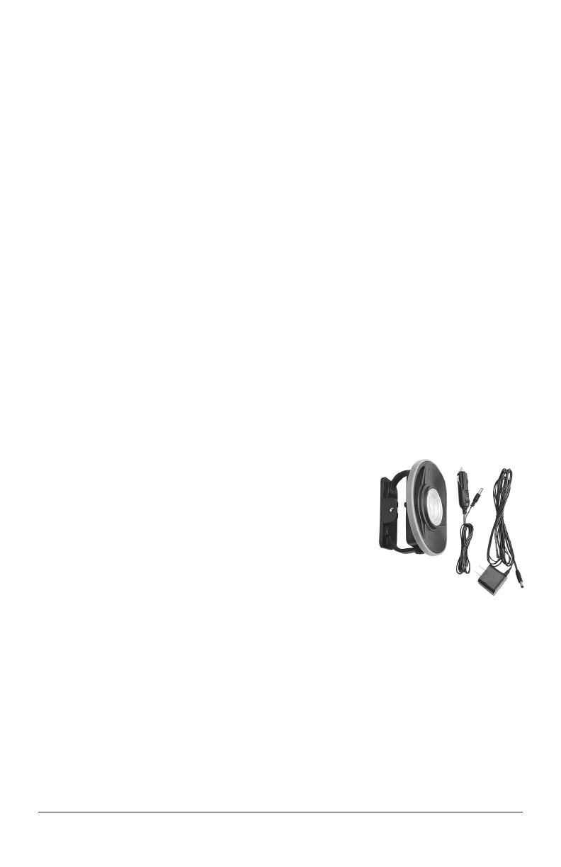
CONTENTS
(1) Eastwood Lighting System Light Module
on adjustable magnetic base
(1) Wall Charger – 120V input, 12V, 1 amp output, 9 ft. cord
(1) 12 Volt DC Power Port Charger – 12V input, 12V 500ma output
SPECIFICATIONS
7.4 Volt, 2200mAh, Li-ion type 18650 Integral Rechargeable Battery
1000 Lumens light output (high), 100 Lumens light output (lowest dimmer setting)
1.5 hours working time (high), 8 hours working time (lowest dimmer setting)
10-Watt COB LED
3-hour charge time
Moisture resistant to IP-65 rating
1 Meter drop rating
To order parts and supplies: 800.343.9353 >> eastwood.com 3
READ INSTRUCTIONS
Thoroughly read and understand this manual before using.
Save for future reference.
EYE INJURY HAZARD!
Do Not allow LED lamps to project directly into eyes.
Temporary blindness may occur.
SHOCK HAZARD!
Keep metal housing of work light away from live electrical sources.
Never operate or store light in damp or wet conditions.
Keep work light away from excessive heat sources to avoid damage.
SAFETY INFORMATION
DANGER indicates a hazardous situation which, if not avoided, will result in death or serious injury.
WARNING indicates a hazardous situation which, if not avoided, could result in death or serious injury.
CAUTION used with the safety alert symbol, indicates a hazardous situation which, if not avoided,
could result in minor or moderate injury.
NOTICE is used to address practices not related to personal injury.
SAFETY INFORMATION
The following explanations are displayed in this manual, on the labeling, and on all other information
provided with this product:
4 Eastwood Technical Assistance: 800.343.9353 >> techelp@eastwood.com
OPERATION
Grip the Handle/Stand and rotate Lamp
through 130° to support or mount lamp
magnetically. NOTE: The Handle/Stand
design allows for quick attachment on the
separately available #32401 Eastwood
Underhood Bracket (not included) or the
#32402 Eastwood Light Tripod
(not included).
Depress and release round Switch located at rear of housing once for Full Brightness and
a 2nd time for Off (FIG 1).
Depress and hold Switch in for 3 seconds (lamp will blink twice) to gradually dim lamp
(will blink twice again when dimmest setting is reached).
Depress and release again to turn Off, depress and hold to resume full brightness.
NOTE: Default setting is Full Brightness. Switching Off and On quickly at any time will
return Lamp to Full Brightness.
CHARGING
When the Lamp fails to illuminate and/or
the 4 Tri-Color (Green, Amber & Red) LED
charge level segments at the rear of the
Housing do not illuminate, a charge is re-
quired. Note that the number of illuminated
LED’s will decrease in number from four to
one as the charge depletes.
- Flip up rubber seal and plug the round
terminal of included Wall Charger or 12 Volt Power Port Cable into rear of Housing (FIG 2).
- Plug wall unit into properly grounded 120 VAC, 60 Hz. outlet
- Allow 3 hours for full charge.
- The array of 4 Green, Amber and Red LED’s at the rear of the Housing will all illuminate
to indicate full charge (FIG 2).
- Close Charging Port Cover to maintain IP-65 rating.
FIG. 1
FIG. 2
To order parts and supplies: 800.343.9353 >> eastwood.com 5
CHARGING WHILE IN USE
The Lamp may be used while charging however it will significantly extend the required charging time.
OPTIONAL ACCESSORIES (Not Included)
#32401 Eastwood Underhood Light Bracket
#32402 Eastwood Light Tripod
#32403 Additional Eastwood Light Module Mount
MOUNTING THE LIGHT MODULE
ON OPTIONAL ACCESSORIES (Not Included)
MOUNTING TO THE # 32401 EASTWOOD UNDERHOOD LIGHT BRACKET.
Flip Latches of the sliding Light Module
Mount upward (FIG 3).
Slide Magnetic Base of Lamp into sliding
Light Module Mount.
Flip Latches of sliding Light Module
Mount downward (FIG 4).
Adjust as required.
MOUNTING TO THE # 32402 EASTWOOD
LIGHT TRIPOD:
Insert Thumbscrew into Tripod Mounting
Plate hole and thread into Magnetic Base of
Light Module (FIG 5).
Adjust as required.
FIG. 3
FIG. 4
FIG. 5
6 Eastwood Technical Assistance: 800.343.9353 >> techelp@eastwood.com
ASSEMBLY OF THE EASTWOOD LIGHTING
SYSTEM ACCESSORIES
#32401 EASTWOOD UNDERHOOD LIGHT BRACKET
Consists of:
(2) Halves of Bracket
(1) Sliding Light Module Mount
(2) Thumb Screws
ASSEMBLING THE # 32401 EASTWOOD
UNDERHOOD LIGHT BRACKET.
Insert the rail on the rear of the sliding Light
Module Mount into the channel of one half
of the Underhood Bracket while simultane-
ously depressing spring-loaded buttons of
the Light Module Mount (FIG 6).
Align the Rubber Covered Hooks and
channels of the Underhood Bracket so
that they are facing the same direction
then slip the open half over the male
connector block (FIG 7).
Using two included Thumb Screws,
secure the two halves together (FIG 8).
Adjust as required.
FIG. 6
FIG. 7
FIG. 8
To order parts and supplies: 800.343.9353 >> eastwood.com 7
#32402 EASTWOOD LIGHTING SYSTEM TRIPOD
Consists of:
(1) Tripod
(1) Long Module
Support Bar
(1) Short Module
Support Bar
(5) Thumb Screws
ASSEMBLING THE #32402
EASTWOOD TRIPOD:
Insert one of the Thumb Screws into
the sliding collar attached to the 3-leg
assembly and thread it securely into the
Main Post and tighten in place (FIG 9).
Using a Thumb Screw, trap the Short
Module Support Bar between the Long
Module Support Bar and top of the
Main Post then thread the Thumbscrew
securely into the Main Post (FIG 9).
Pass a Thumb Screw through the open
hole in the Light Module Support Bar and
thread it into the Magnetic Base of the
Light Module (FIG 9).
Adjust as required.
Utilize the remaining two Thumbscrews
to attach additional #32400 Eastwood
Light Modules.
FIG. 9
Long
Module
Support
Bar
Thumbscrews
Short Support Bar
© Copyright 2018 Easthill Group, Inc. 3/18 Instruction item #32404Q Rev 1
If you have any questions about the use of this product, please contact
The Eastwood Technical Assistance Service Department: 800.343.9353 >> email: techelp@eastwood.com
PDF version of this manual is available at eastwood.com
The Eastwood Company 263 Shoemaker Road, Pottstown, PA 19464, USA
800.343.9353 eastwood.com
  • Page 1 1
  • Page 2 2
  • Page 3 3
  • Page 4 4
  • Page 5 5
  • Page 6 6
  • Page 7 7
  • Page 8 8

Eastwood 32400 Operating instructions

Type
Operating instructions

Ask a question and I''ll find the answer in the document

Finding information in a document is now easier with AI