Page is loading ...

Graco Inc., PO Box 1441, Minneapolis, MN 55440-1441
Copyright 2004, Graco Inc. is registered to I.S. EN ISO 9001
310824C
Repair
390
™
Airless Sprayer
- For portable spray applications of architectural paints and coatings -
3300 psi (22.7MPa, 227bar) Maximum Working Pressure
*all models not available in all countries
IMPORTANT SAFETY INSTRUCTIONS!
Read all warnings and instructions. Save these instructions. Contact Graco Customer Service
or your local Graco distributor to obtain a manual in your language.
Model #* VAC Country
248800 / 248802 / 826055
120 North America
✔
248804 / 248806
240 Europe / Europe
multicord
✔
248808
240 Asia / Australia
✔
248810
110 UK
✔
TIA
ti5634a
Related Manuals
310820
309639
309250
310876

Manual Conventions
2 310824C
Contents
Manual Conventions . . . . . . . . . . . . . . . . . . . . . . . . 2
Warnings . . . . . . . . . . . . . . . . . . . . . . . . . . . . . . . . . 3
Component Identification . . . . . . . . . . . . . . . . . . . . 5
Installation . . . . . . . . . . . . . . . . . . . . . . . . . . . . . . . . 6
Pressure Relief Procedure . . . . . . . . . . . . . . . . . . . 7
General Repair Information . . . . . . . . . . . . . . . . . . 8
Troubleshooting . . . . . . . . . . . . . . . . . . . . . . . . . . . . 9
Displacement Pump Replacement . . . . . . . . . . . . 13
Drive Housing Replacement . . . . . . . . . . . . . . . . . 15
Spin Test . . . . . . . . . . . . . . . . . . . . . . . . . . . . . . . . . 16
Fan Replacement . . . . . . . . . . . . . . . . . . . . . . . . . . 17
Motor Brush Replacement . . . . . . . . . . . . . . . . . . 18
Control Board Replacement . . . . . . . . . . . . . . . . . 19
Fuse Replacement . . . . . . . . . . . . . . . . . . . . . . . . . 21
Pressure Control Assembly Replacement . . . . . . 22
Manifold Replacement . . . . . . . . . . . . . . . . . . . . . . 23
Power Cord Replacement . . . . . . . . . . . . . . . . . . . 24
Motor Replacement . . . . . . . . . . . . . . . . . . . . . . . . 25
Wiring Diagram . . . . . . . . . . . . . . . . . . . . . . . . . . . 26
Technical Data . . . . . . . . . . . . . . . . . . . . . . . . . . . . 27
Graco Standard Warranty . . . . . . . . . . . . . . . . . . . 29
Graco Information . . . . . . . . . . . . . . . . . . . . . . . . . 30
Manual Conventions
Note
WARNING
WARNING: a potentially hazardous situation which, if
not avoided, could result in death or serious injury.
Warnings in the instructions usually include a symbol
indicating the hazard. Read the general Warnings
section for additional safety information.
Hazard Symbol
CAUTION
CAUTION: a potentially hazardous situation which, if
not avoided, may result in property damage or
destruction of equipment.
Additional helpful information.

Warnings
310824C 3
Warnings
The following are general warnings related to the safe setup, use, grounding, maintenance, and repair of this equip-
ment. Additional, more specific warnings may be found throughout the text of this manual where applicable.
WARNING
FIRE AND EXPLOSION HAZARD
Flammable fumes, such as solvent and paint fumes, in work area can ignite or explode. To help prevent
fire and explosion:
• Use equipment only in well ventilated area.
• When flammable liquid is used in or near sprayer or for flushing or cleaning, keep sprayer at least 20
feet (6 m) away from explosive vapors.
• Eliminate all ignition sources; such as pilot lights, cigarettes, portable electric lamps, and plastic drop
cloths (potential static arc).
• Keep work area free of debris, including solvent, rags and gasoline.
• Do not plug or unplug power cords, or turn power or light switches on or off when flammable fumes
are present.
• Ground equipment and conductive objects in work area. See Grounding instructions.
• Use only grounded hoses.
• Hold gun firmly to side of grounded pail when triggering into pail.
• If there is static sparking or you feel a shock, stop operation immediately. Do not use equipment
until you identify and correct the problem.
• Keep a fire extinguisher in the work area.
ELECTRIC SHOCK HAZARD
Improper grounding, setup, or usage of the system can cause electric shock.
• Turn off and disconnect power cord before servicing equipment.
• Use only grounded electrical outlets.
• Use only 3-wire extension cords.
• Ensure ground prongs are intact on sprayer and extension cords.
INJECTION HAZARD
High-pressure fluid from gun, hose leaks, or ruptured components will pierce skin. This may look like just
a cut, but it is a serious injury that can result in amputation. Get immediate medical attention.
• Do not point gun at anyone or at any part of the body.
• Do not put your hand over the spray tip.
• Do not stop or deflect leaks with your hand, body, glove, or rag.
• Do not spray without tip guard and trigger guard installed.
• Engage trigger lock when not spraying.
• Follow Pressure Relief Procedure in this manual, when you stop spraying and before cleaning,
checking, or servicing equipment.

Warnings
4 310824C
EQUIPMENT MISUSE HAZARD
Misuse can cause death or serious injury.
• Do not exceed the maximum working pressure or temperature rating of the lowest rated system
component. See Technical Data in all equipment manuals.
• Use fluids and solvents that are compatible with equipment wetted parts. See Technical Data in all
equipment manuals. Read fluid and solvent manufacturer’s warnings.
• Check equipment daily. Repair or replace worn or damaged parts immediately.
• Do not alter or modify equipment.
• Use equipment only for its intended purpose. Call your Graco distributor for information.
• Route hoses and cables away from traffic areas, sharp edges, moving parts, and hot surfaces.
• Do not kink or overbend hoses or use hoses to pull equipment.
• Keep children and animals away from work area.
• Comply with all applicable safety regulations.
PRESSURIZED ALUMINUM PARTS HAZARD
Do not use 1,1,1-trichloroethane, methylene chloride, other halogenated hydrocarbon solvents or fluids
containing such solvents in pressurized aluminum equipment. Such use can cause serious chemical
reaction and equipment rupture, and result in death, serious injury, and property damage.
BURN HAZARD
Equipment surfaces can become very hot during operation. To avoid severe burns, do not touch hot
equipment. Wait until equipment has cooled completely.
MOVING PARTS HAZARD
Moving parts can pinch or amputate fingers and other body parts.
• Keep clear of moving parts.
• Do not operate equipment with protective guards or covers removed.
• Pressurized equipment can start without warning. Before checking, moving, or servicing equipment,
follow the Pressure Relief Procedure in this manual. Disconnect power or air supply.
PERSONAL PROTECTIVE EQUIPMENT
You must wear appropriate protective equipment when operating, servicing, or when in the operating
area of the equipment to help protect you from serious injury, including eye injury, inhalation of toxic
fumes, burns, and hearing loss. This equipment includes but is not limited to:
• Protective eyewear
• Clothing and respirator as recommended by the fluid and solvent manufacturer
•Gloves
• Hearing protection
WARNING

Component Identification
310824C 5
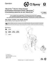
Component Identification
K
E
H
B
A
D
J
F
ti5636b
N
M
PR S
C
G
Item English
A Pressure Control
BON/OFF switch
C Pressure Gauge (not on all models)
DPower Cord
E Fluid Outlet
FPrime Valve
G Cord Wrap
HPump
J Suction Hose
KDrain Hose
MFluid Hose
NGun
PTip
R Guard
S Trigger Safety Lock

Installation
6 310824C
Installation
Grounding and Electric
Requirements
The sprayer cord includes: a grounding wire with an
appropriate grounding contact.
The sprayer requires:
110-120V Units: 100-130VAC, 50/60 Hz, 11A, 1 phase,
circuit with a grounding receptacle.
240V Units: 210-255 VAC, 50/60 Hz, 7.5A, 1 phase, cir-
cuit with a grounding receptacle.
Never use an outlet that is not grounded or an
adapter.
Do not use the sprayer if the electrical cord has a dam-
aged ground contact. Only use an extension cord with
an undamaged ground contact.
Recommended extension cords for use with this
sprayer:
• 110-120V: 3-wire, 12 AWG (2.5 mm
2
) minimum, 300
ft. (90 m) maximum length.
• 240V: 3-wire, 16 AWG (1.0 mm
2
) minimum, 300 ft
(90 m) maximum length.
Spray gun: ground through connection to a properly
grounded fluid hose and pump.
Fluid supply container: follow local code.
Solvent and Oil-based fluids: follow local code. Use
only conductive metal pails placed on a grounded sur-
face such as concrete. Do not place the pail on a non-
conductive surface such as paper or cardboard, which
interrupts grounding continuity.
Grounding the metal pail: connect a ground wire to the
pail by clamping one end to pail and other end to ground
such as a water pipe.
To maintain grounding continuity when flushing or
relieving pressure: hold metal part of the spray gun
firmly to the side of a grounded metal pail, then trigger
the gun.
WARNING
Your system must be grounded. Read warnings, page
3.
Smaller gauge or longer extension cords may
reduce sprayer performance.

Pressure Relief Procedure
310824C 7
Pressure Relief Procedure
1. Turn OFF power and turn pressure control to lowest
pressure setting.
2. Hold gun against side of grounded metal flushing
pail. Trigger gun to relieve pressure.
3. Turn prime valve down.
If you suspect the spray tip or hose is clogged or that
pressure has not been fully relieved after following the
steps above, VERY SLOWLY loosen tip guard retaining
nut or hose end coupling to relieve pressure gradually,
then loosen completely. Clear hose or tip obstruction.
4. Engage trigger safety lock on gun if unit is being
shut down or left unattended.
WARNING
Follow this Pressure Relief Procedure whenever you
are instructed to relieve pressure, stop spraying, check
or service equipment or install or clean spray tip. Read
Injection Hazard Warning, page 3.
FLUSH
ti5310a
ti5304a

General Repair Information
8 310824C
General Repair Information
• Keep all screws, nuts, washers, gaskets, and electri-
cal fittings removed during repair procedures. These
parts usually are not provided with replacement kits.
• Test repairs after problems are corrected.
• If sprayer does not operate properly, review repair
procedure to verify you did it correctly. See Trouble-
shooting, page 9.
• Overspray may build up in the air passages.
Remove any overspray and residue from air pas-
sages and openings in the enclosures whenever
you service sprayer.
• Do not operate the sprayer without the motor shroud
in place. Replace if damaged. Motor shroud directs
cooling air around motor to prevent overheating and
insulate the control board from accidental electric
shock.
WARNING
Read Electric Shock Warning, page 3 and Burn
Hazard Warning, page 4.
WARNING
Flammable materials spilled on hot, bare, motor could
cause fire or explosion. To reduce risk of burns, fire or
explosion, do not operate sprayer with cover removed.
WARNING
To reduce risk of serious injury, including electric
shock:
• Do not touch moving or electric parts with fingers
or tools while testing repair.
• Unplug sprayer when power is not required for
testing.
• Install all covers, gaskets, screws and washers
before you operate sprayer.
CAUTION
• Do not run sprayer dry for more than 30 seconds.
Doing so could damage pump packings.
• Protect the internal drive parts of this sprayer from
water. Openings in the cover allow for air cooling of
the mechanical parts and electronics inside. If
water gets in these openings, the sprayer could
malfunction or be permanently damaged.
• Prevent pump corrosion and damage from freezing.
Never leave water or water-base paint in sprayer
when its not in use in cold weather. Freezing fluids
can seriously damage sprayer. Store sprayer with
Pump Armor to protect sprayer during storage.

Troubleshooting
310824C 9
Troubleshooting
WARNING
Read Electric Shock Warning, page 3, Burn Hazard
Warning, page 4 and Pressure Relief Procedure,
page 7.
Problem
What To Check
(If check is OK, go to next check)
What To Do
(When check is not OK, refer to this column)
Motor Won’t Operate
Basic Fluid Pressure 1. Pressure control knob setting.
Motor will not run if set at mini-
mum (fully counter-clockwise).
Slowly increase pressure setting to see if motor
starts.
2. Spray tip or fluid filter may be
clogged.
Relieve pressure, page 7. Then clear clog or
clean gun filter. Refer to gun instruction manual,
309639.
Basic Mechanical 1. Pump frozen or hardened paint Thaw sprayer if water or water-based paint has
frozen in sprayer. Place sprayer in warm area to
thaw. Do not start sprayer until thawed com-
pletely. If paint hardened (dried) in sprayer,
replace pump packings. See page 13, Dis-
placement Pump Replacement.
2. Displacement pump connecting
rod pin. Pin must be completely
pushed into connecting rod and
retaining spring must be firmly in
groove or pump pin.
Push pin into place and secure with spring
retainer. See page 13, Displacement Pump
Replacement.
3. Motor. Remove drive housing
assembly. See page 15, Drive
Housing Replacement. Try to
rotate fan by hand.
Replace motor if fan won’t turn. See page 26,
Motor Replacement.

Troubleshooting
10 310824C
Basic Electrical
See wiring diagram, page
27
1. Electric supply. Meter must read
100-130 VAC for 110-120 VAC
models and 210-255 VAC for 240
VAC models.
Reset building circuit breaker, replace building
fuses. Try another outlet.
2. Extension cord. Check extension
cord continuity with volt meter.
Replace extension cord.
3. Sprayer power supply cord.
Inspect for damage such as bro-
ken insulation or wires.
Replace power supply cord. See page 25,
Power Cord Replacement.
4. Fuse. Check replaceable fuse on
control board (next to ON/OFF
switch).
Replace fuse after completing motor inspection.
See page 21, Fuse Replacement.
5. Motor leads are securely fas-
tened and properly connected to
control board.
Replace loose terminals; crimp to leads. Be
sure terminals are firmly connected.
Clean circuit board terminals. Securely recon-
nect leads.
6. Motor thermal switch. Yellow
motor leads must have continuity
through thermal switch.
Replace motor. See page 26, Motor Replace-
ment.
7. Brush cap missing or loose brush
lead connections.
Install brush cap or replace brushes if leads are
damaged. See page 18, Motor Brush
Replacement.
8. Brush length which must be 1/4
in. (6mm) minimum.
NOTE: Brushes do not wear at
the same rate on both sides of
motor. Check both brushes.
Replace brushes. See page 18, Motor Brush
Replacement.
9. Motor armature commutator for
burn spots, gouges and extreme
roughness.
Remove motor and have motor shop resurface
commutator if possible. See page 26, Motor
Replacement.
10. Motor armature for shorts using
armature tester (growler) or per-
form spin test, page 16.
Replace motor. See page 26, Motor Replace-
ment.
11. Pressure control not plugged in
to control board.
Insert pressure control connector into control
board.
Problem
What To Check
(If check is OK, go to next check)
What To Do
(When check is not OK, refer to this column)

Troubleshooting
310824C 11
Low Output 1. Worn spray tip. Relieve pressure, page 7. Replace tip. Refer to
gun instruction manual, 309639.
2. Verify pump does not continue to
stroke when gun trigger is
released.
Service pump. See page 13, Displacement
Pump Replacement.
3. Prime valve leaking. Relieve pressure, page 7. Then repair prime
valve. See page 23, Manifold Replacement.
4. Suction hose connections. Tighten any loose connections. Check o-rings
on suction hose swivel.
5. Electric supply with volt meter.
Meter must read 100-130 VAC for
110-120 VAC models and
210-255 for 240 VAC models.
Low voltages reduce sprayer per-
formance.
Reset building circuit breaker; replace building
fuse. Repair electrical outlet or try another
outlet.
6. Extension cord size and length. 7. Replace with a correct, grounded extension
cord. See page 6, Grounding and Electric
Requirements.
8. Leads from motor to circuit board
for damaged or loose wire con-
nectors. Inspect wiring insulation
and terminals for signs of over-
heating.
Be sure male terminal pins are centered and
firmly connected to female terminals. Replace
any loose terminals or damaged wiring.
Securely reconnect terminals.
9. Worn motor brushes which must
be 1/4 in. (6 mm) minimum.
Replace brushes. See page 18. Motor Brush
Replacement.
10. Motor brushes binding in brush
holders.
Clean brush holders. Remove carbon dust by
using compressed air to blow out brush dust.
11. Low stall pressure. Turn pressure
control knob fully clockwise.
Replace pressure control assembly. See page
22, Pressure Control Assembly Replace-
ment.
12. Motor armature for shorts by
using an armature tester
(growler) or perform spin test,
page 16.
Replace motor. See page 26, Motor
Replacement.
Problem
What To Check
(If check is OK, go to next check)
What To Do
(When check is not OK, refer to this column)

Troubleshooting
12 310824C
Motor runs and pump
strokes
1. Prime Valve Open. Close prime valve.
2. Paint supply. Refill and reprime pump.
3. Intake strainer clogged. Remove and clean, then reinstall.
4. Suction hose leaking air. Tighten nut. Check o-rings on swivel.
5. Intake valve ball and piston ball
are seating properly.
See Pump Manual 309250. Strain paint before
using to remove particles that could clog pump.
6. Leaking around throat packing
nut which may indicate worn or
damaged packings.
See Pump Manual 309250.
7. Pump rod damaged. See Pump Manual 309250.
Motor runs but pump does
not stroke
1. Displacement pump pin dam-
aged or missing.
Replace pump pin if missing. Be sure retaining
spring is fully in groove all around connecting
rod. See page 13, Displacement Pump
Replacement.
2. Connecting rod assembly for
damage.
Replace connecting rod assembly. See page
13, Displacement Pump Replacement.
3. Gears or drive housing. Inspect drive housing assembly and gears for
damage and replace if necessary. See page 15,
Drive Housing Replacement.
Motor is hot and runs
intermittently
1. Be sure ambient temperature
where sprayer is located is not
more than 115°F (46°C) and
sprayer is not located in direct
sun.
Move sprayer to shaded, cooler area if possible.
2. Motor has burned windings indi-
cated by removing positive (red)
brush and seeing burned adja-
cent commutator bars.
Replace motor. See page 26, Motor
Replacement.
3. Tightness of pump packing nut.
Overtightening tightens packings
on rod, restricts pump action and
damages packings.
Loosen packing nut. Check for leaking around
throat. Replace pump packings if necessary.
See pump manual 309250.
Problem
What To Check
(If check is OK, go to next check)
What To Do
(When check is not OK, refer to this column)

Displacement Pump Replacement
310824C 13
Displacement Pump Replacement
See manual 309250 for pump repair instructions.
Removal
1. Relieve pressure, page 7.
2. Loosen two screws (30) and rotate cover (44).
3. Loosen nut (A) and remove hose set (35). Loosen
nut (B) and remove the high pressure hose (14).
4. Cycle pump until pin (32) is in position to be
removed.
5. Disconnect power cord from outlet.
6. Using a flat screwdriver, push retaining spring (C)
up. Push out pump pin (32).
7. Using a hammer, loosen pump jam nut (11).
Unscrew and remove pump (9).
WARNING
Read Injection Hazard Warning, page 3, Moving
Parts Hazard Warning, page 4 and Pressure Relief
Procedure, page 7.
44
30
ti6104a
14
B
A
35
ti6105a
32
ti6106a
C
11
9
11
ti6107a

Displacement Pump Replacement
14 310824C
Installation
1. Extend pump piston rod full. Apply grease to top of
pump rod at (D) or inside connecting rod (7). Install
jam nut (11) on pump threads.
2. Install pump rod (D) into connecting rod (7).
3. Install pump pin (32). Verify retainer spring (C) is in
groove over pump pin.
4. Push pump (9) up until pump threads engage.
5. Screw in pump until threads are flush with top of
drive housing opening.
6. Align pump outlet (E) to back.
7. Screw jam nut (11) up onto pump until nut stops.
Tighten jam nut by hand, then tap 1/8 to 1/4 turn
with a 20 oz (maximum) hammer to approximately
75 ft-lb (102 N•m).
8. Install suction tube (35) and high pressure hose
(14). Tighten nuts (A) and (B).
.
9. Fill packing nut with Graco TSL until fluid flows onto
top of seal.
10. Rotate cover (44). Tighten screws (30).
WARNING
If pump pin works loose, parts could break off due to
force of pumping action. Parts could project through
air and result in serious injury or property damage.
CAUTION
If the pump jam nut loosens during operation, the
threads of the drive housing will be damaged.
$
TIA
#
TIA
%
14
B
A
35
ti6105a
44
30
ti5735a

Drive Housing Replacement
310824C 15
Drive Housing Replacement
Removal
1. Relieve pressure, page 7.
2. Remove pump (9). Displacement Pump Replace-
ment, page 13. Disconnect power cord from outlet.
3. Remove two screws (30) and cover (32).
4. Remove four screws (6).
5. Pull drive housing (5) out of motor front endbell.
6. Remove gear cluster (2) and (3) and thrust bearing
(4) from drive housing.
Installation
1. Apply a liberal coat of grease to gears and needle
bearing surfaces. Install thrust bearing (4) and
gears (2) and (3) in front endbell housing.
2. Push drive housing into front endbell housing. Insert
gear crank (3) through hole in connecting rod (7).
3. Install four screws (6).
4. Install cover (32) with two screws (30).
5. Install pump (9). Displacement Pump Replace-
ment, page 13.
WARNING
Read Injection Hazard Warning, page 3 and , page
7.
CAUTION
Do not drop gear cluster (3) and (2) when removing
drive housing (5). Gear cluster may stay engaged in
motor front endbell or drive housing.
5
30
6
32
6
3
2
ti5641a
7
4
2
4
3
ti6121a
Needle
bearing
surfaces
3
7
ti6124a

Spin Test
16 310824C
Spin Test
See Wiring Diagram, page 27.
To check armature, motor winding and brush electrical
continuity:
1. Relieve pressure, page 7. Disconnect power cord
from outlet.
2. Remove two screws (30) and shroud (29).
3. Remove drive housing (5), page 15.
4. Disconnect motor connector (F).
Armature Short Circuit Test
Quickly turn motor fan by hand. If motor coasts two or
three revolutions before complete stop, there are no
electrical shorts. If motor does not spin freely, armature
is shorted. Replace motor, page 26.
Armature, Brushes, and Motor Wiring Open
Circuit Test (Continuity)
1. Connect red and black motor leads with test lead.
Turn motor fan by hand at about two revolutions per
second.
2. If uneven or no resistance, check for missing brush
caps, broken brush springs, brush leads, and worn
brushes. Repair as needed, page 18.
3. If still uneven or no resistance, replace motor, page
26.
4. Reattach motor connector (F).
5. Replace drive housing, page 15.
6. Replace shroud (29) and two screws (30).
WARNING
Read Electric Shock Warning, page 3 and Pressure
Relief Procedure, page 7.
30
29
F
ti5638a

Fan Replacement
310824C 17
Fan Replacement
Removal
1. Relieve pressure, page 7. Disconnect power cord
from outlet.
2. Remove two screws (30) and shroud (29).
3. Remove spring clip (101) on back of motor.
4. Pull off fan (100).
Installation
1. Slide new fan (100) in place on back of motor. Be
sure blades of fan face motor as shown.
2. Install spring clip (101).
3. Replace shroud (29) and two screws (30).
WARNING
Read Electric Shock Warning, page 3 and Pressure
Relief Procedure, page 7.
29
100
101
ti5769a
30

Motor Brush Replacement
18 310824C
Motor Brush Replacement
See Wiring Diagram, page 27.
Removal
Replace brushes worn to less than 1/4 in. (6mm).
Brushes wear differently on each side of motor, check
both sides.
1. Relieve pressure, page 7. Disconnect power cord
from outlet.
2. Remove two screws (30) and shroud (29).
3. Disconnect motor connector (D) from control board
(33).
4. Cut tie wrap (F).
5. Locate two yellow wires (C) (thermal leads). Cut
each yellow wire at the center.
6. Using a flat screwdriver, pry off (two) brush caps
(A). Remove brushes (B) from motor.
7. Discard old brush harness.
8. While rotating fan by hand, using compressed air,
blow air into positive (top) brush holder to remove
brush dust.
Installation
\
1. With wires facing toward front of motor, install new
brushes (B) in motor. Be sure to install the positive
(red) brush lead in the top of the motor (as shown)
and the negative (black) brush lead in the side of the
motor.
2. Push each cap (A) into place over brush. Orient
each cap with the 2 projections on either side of the
brush lead. You will hear a “snap” when cap is
securely in place.
3. Using a wire stripper, strip off wire insulation approx-
imately 1/4 inch (6 mm) from the end of each yellow
wire (C) to the motor.
4. Insert stripped end into end of a butt splice (E) on
new brush assembly.
5. Use a crimping tool to squeeze the ends of the butt
splice (E) tightly around each wire. Pull gently on
each wire to be sure it will not pull out of the butt
splice.
6. Using new tie wrap (F) from kit, wrap tie around
motor and wires only. Trim off excess. Be sure pres-
sure hose and wire leads are not caught in tie wrap.
7. Reconnect motor connector (D) to control board
(33).
8. Replace shroud (29) and two screws (30).
WARNING
Read Electric Shock Warning, page 3 and Pressure
Relief Procedure, page 7.
To contain the dust, turn on your shop vac. Place
the end of the hose over the negative (lower) brush
holder while blowing compressed air into the posi-
tive (top) brush holder.
Use all new parts included in your brush kit. Do not
reuse old parts if new replacement parts are pro-
vided.
30
29
33
ti5637a
A
B
+
-
C
D
E
ti5637a
F
D
A
Red
Black

Control Board Replacement
310824C 19
Control Board Replacement
See Wiring Diagram, page 27.
Removal
1. Relieve pressure, page 7. Disconnect power cord
from outlet.
2. Remove two screws (30) and shroud (29).
3. Disconnect pressure switch connector (A) from con-
trol board (33).
4. Disconnect motor connector (B) from control board
(33).
5. Remove 3 screws (30) securing control board to
housing (2 are located on the front and one on the
back next to the power cord).
6. Pull control board out slightly and then slide it back
and off of frame.
7. Remove grommet and wires from strain relief.
.
8. Remove 2 power cord connectors from control
board.
WARNING
Read Electric Shock Warning, page 3 and Pressure
Relief Procedure, page 7.
30
33
30
ti6119a
Make sure power cord is free and NOT wrapped
around cord wrap.
Ground wire will remain attached to sprayer with
grounding screw.
33
240V
A
B
33
120V
B
A

Control Board Replacement
20 310824C
Installation
1. Position grommet and power cord wires through
strain relief in control board (33).
2. Reconnect the power cord connectors to the correct
terminals indicated on the control board (120V,
black and white, 240V, blue and brown) on control
board (33).
3. Carefully slide control board back into place on the
side of the motor frame.
4. Replace 3 screws (30). Torque to 30-35 in-lbs
(3.4-3.9 N.m)
5. Reattach motor connector (B) and pressure control
assembly connector (A).
6. Install shroud (29) and two screws (30).
Be sure power cord is routed between the blue high
pressure hose to the manifold and the sprayer
frame.
33
ti6122a
ti6125a
A
B
33
120V
H
B
A
J
G
F
E
D
ti5639a
30
33
30
/