
KMA-700/KMA-500
Digital Karaoke Mixing Amplifier
U
OWNER’S MANUAL
MANUAL DE INSTRUCCIONES

i En
1 Read these instructions.
2 Keep these instructions.
3 Heed all warnings.
4 Follow all instructions.
5 Do not use this apparatus near water.
6 Clean only with dry cloth.
7 Do not block any ventilation openings. Install in accordance
with the manufacturer’s instructions.
8 Do not install near any heat sources such as radiators, heat
registers, stoves, or other apparatus (including amplifiers) that
produce heat.
9 Do not defeat the safety purpose of the polarized or
grounding-type plug. A polarized plug has two blades with
one wider than the other. A grounding type plug has two
blades and a third grounding prong. The wide blade or the
third prong are provided for your safety. If the provided plug
does not fit into your outlet, consult an electrician for
replacement of the obsolete outlet.
10 Protect the power cord from being walked on or pinched
particularly at plugs, convenience receptacles, and the point
where they exit from the apparatus.
11 Only use attachments/accessories specified by the
manufacturer.
12 Use only with the cart, stand, tripod, bracket,
or table specified by the manufacturer, or sold
with the apparatus. When a cart is used, use
caution when moving the cart/apparatus
combination to avoid injury from tip-over.
13 Unplug this apparatus during lightning storms or when unused
for long periods of time.
14 Refer all servicing to qualified service personnel. Servicing is
required when the apparatus has been damaged in any way,
such as power cord or plug is damaged, liquid has been spilled
or objects have fallen into the apparatus, the apparatus has
been exposed to rain or moisture, does not operate normally,
or has been dropped.
IMPORTANT SAFETY INSTRUCTIONS
CAUTION
RISK OF ELECTRIC SHOCK DO
NOT OPEN
CAUTION: TO REDUCE THE RISK OF
ELECTRIC SHOCK, DO NOT REMOVE COVER
(OR BACK). NO USER-SERVICEABLE PARTS
INSIDE. REFER SERVICING TO QUALIFIED
SERVICE PERSONNEL.
• Explanation of Graphical Symbols
The lightning flash with arrowhead symbol, within an
equilateral triangle, is intended to alert you to the
presence of uninsulated “dangerous voltage” within
the product’s enclosure that may be of sufficient
magnitude to constitute a risk of electric shock to
persons.
The exclamation point within an equilateral triangle
is intended to alert you to the presence of important
operating and maintenance (servicing) instructions in
the literature accompanying the appliance.
IMPORTANT
Please record the serial number of this unit in the space
below.
MODEL:
Serial No.:
The serial number is located on the rear of the unit.
Retain this Owner’s Manual in a safe place for future
reference.

IMPORTANT SAFETY INSTRUCTIONS
ii En
Yamaha and the Electronic Industries Association’s Consumer Electronics Group want you to get the most out of your
equipment by playing it at a safe level. One that lets the sound come through loud and clear without annoying blaring or
distortion – and, most importantly, without affecting your sensitive hearing. Since hearing damage from loud sounds is
often undetectable until it is too late, Yamaha and the Electronic Industries Association’s Consumer Electronics Group
recommend you to avoid prolonged exposure from excessive volume levels.
FCC INFORMATION (for US customers)
1 IMPORTANT NOTICE: DO NOT MODIFY THIS
UNIT!
This product, when installed as indicated in the
instructions contained in this manual, meets FCC
requirements. Modifications not expressly approved by
Yamaha may void your authority, granted by the FCC, to
use the product.
2IMPORTANT: When connecting this product to
accessories and/or another product use only high quality
shielded cables. Cable/s supplied with this product MUST
be used. Follow all installation instructions. Failure to
follow instructions could void your FCC authorization to
use this product in the USA.
3 NOTE: This product has been tested and found to comply
with the requirements listed in FCC Regulations, Part 15
for Class “B” digital devices. Compliance with these
requirements provides a reasonable level of assurance that
your use of this product in a residential environment will
not result in harmful interference with other electronic
devices.
This equipment generates/uses radio frequencies and, if
not installed and used according to the instructions found
in the users manual, may cause interference harmful to the
operation of other electronic devices.
Compliance with FCC regulations does not guarantee that
interference will not occur in all installations. If this
product is found to be the source of interference, which can
be determined by turning the unit “OFF” and “ON”, please
try to eliminate the problem by using one of the following
measures:
Relocate either this product or the device that is being
affected by the interference.
Utilize power outlets that are on different branch (circuit
breaker or fuse) circuits or install AC line filter/s.
In the case of radio or TV interference, relocate/reorient
the antenna. If the antenna lead-in is 300 ohm ribbon lead,
change the lead-in to coaxial type cable.
If these corrective measures do not produce satisfactory
results, please contact the local retailer authorized to
distribute this type of product. If you can not locate the
appropriate retailer, please contact Yamaha Electronics
Corp., U.S.A. 6660 Orangethorpe Ave., Buena Park, CA
90620.
The above statements apply ONLY to those products
distributed by Yamaha Corporation of America or its
subsidiaries.
We Want You Listening For A Lifetime

iii En
1 To assure the finest performance, please read this manual
carefully. Keep it in a safe place for future reference.
2 Install this sound system in a well ventilated, cool, dry, clean
place – away from direct sunlight, heat sources, vibration,
dust, moisture, and/or cold. Allow ventilation space of at least
10 cm (3-15/16”) on the top, left and right of this unit, and
20 cm (7-7/8”) on the back.
3 Locate this unit away from other electrical appliances, motors,
or transformers to avoid humming sounds.
4 Do not expose this unit to sudden temperature changes from
cold to hot, and do not locate this unit in an environment with
high humidity (i.e. a room with a humidifier) to prevent
condensation inside this unit, which may cause an electrical
shock, fire, damage to this unit, and/or personal injury.
5 Avoid installing this unit where foreign objects may fall onto
this unit and/or this unit may be exposed to liquid dripping or
splashing. On the top of this unit, do not place:
– Other components, as they may cause damage and/or
discoloration on the surface of this unit.
– Burning objects (i.e. candles), as they may cause fire,
damage to this unit, and/or personal injury.
– Containers with liquid in them, as they may fall and liquid
may cause electrical shock to the user and/or damage to
this unit.
6 Do not cover this unit with a newspaper, tablecloth, curtain,
etc. in order not to obstruct heat radiation. If the temperature
inside this unit rises, it may cause fire, damage to this unit,
and/or personal injury.
7 Do not plug in this unit to an AC wall outlet until all
connections are complete.
8 Do not operate this unit upside-down. It may overheat,
possibly causing damage.
9 Do not use force on switches, knobs and/or cords.
10 When disconnecting the power cord from the AC wall outlet,
grasp the plug; do not pull the cord.
11 Do not clean this unit with chemical solvents; this might
damage the finish. Use a clean, dry cloth.
12 Only voltage specified on this unit must be used. Using this
unit with a higher voltage than specified is dangerous and may
cause fire, damage to this unit, and/or personal injury.
Yamaha will not be held responsible for any damage resulting
from use of this unit with a voltage other than specified.
13 To prevent damage by lightning, keep the power cord
disconnected from an AC wall outlet or the unit during a
lightning storm.
14 Do not attempt to modify or fix this unit. Contact qualified
Yamaha service personnel when any service is needed. The
cabinet should never be opened for any reasons.
15 When not planning to use this unit for long periods of time
(i.e. vacation), disconnect the AC power plug from the AC
wall outlet.
16 Install this unit near the wall outlet and where the AC power
plug can be reached easily.
17 Be sure to read the “Troubleshooting” section on common
operating errors before concluding that this unit is faulty.
18 Before moving this unit, press POWER switch to turn this
unit off, and disconnect the power cord from the AC wall
outlet.
19 The batteries shall not be exposed to excessive heat such as
sunshine, fire or like.
20 Condensation will form when the surrounding temperature
changes suddenly. Disconnect the power supply cable from
the outlet, then leave the unit alone.
21 When using the unit for a long time, the unit may become
warm. Turn the power off, then leave the unit alone for
cooling.
22 VOLTAGE SELECTOR (Except U.S.A. model)
The VOLTAGE SELECTOR on the rear panel of this unit
must be set for your local main voltage BEFORE plugging
into the AC wall outlet.
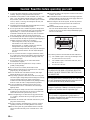
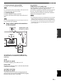
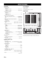
Caution: Read this before operating your unit
The following rack size measurements must be adhered to:
12 The ventilation space on the top, left and right of this
unit; more than 10 cm (3-15/16”)
3 The ventilation space on the back of this unit; more
than 20 cm (7-7/8”)
4 Do not remove the feet.
WARNING
TO REDUCE THE RISK OF FIRE OR ELECTRIC
SHOCK, DO NOT EXPOSE THIS UNIT TO RAIN
OR MOISTURE.
As long as this unit is connected to the AC wall outlet,
it is not disconnected from the AC power source even
if you turn off this unit by POWER switch.
CAUTION
Danger of explosion if battery is incorrectly replaced.
Replace only with the same or equivalent type.
CAUTION
Use of controls or adjustments or performance of
procedures other than those specified herein may result
in hazardous radiation exposure.
foot foot
rack

1 En
PREPARATIONINTRODUCTION
OPERATION
ADDITIONAL
INFORMATION
English
HANDLING PRECAUTIONS..............................2
BEFORE CONNECTING.....................................2
NAMES OF PARTS AND THEIR FUNCTIONS
..............................................................................3
SYSTEM CONNECTIONS...................................6
CONNECTIONS ....................................................7
CONFIGURATION DIAGRAM ........................10
REMOTE CONTROL.........................................11
GENERAL OPERATION...................................13
SETUP MODE......................................................14
TROUBLESHOOTING.......................................16
MAINTENANCE .................................................16
AFTER-SALES SERVICING.............................17
KARAOKE ETIQUETTE...................................17
COPYRIGHT .......................................................17
SPECIFICATIONS..............................................18
CONTENTS
INTRODUCTION
PREPARATION
OPERATION
ADDITIONAL INFORMATION

2 En
INTRODUCTION
Thank you for your purchase of the Yamaha KMA-700/KMA-500 Digital Karaoke Mixing Amplifier.
This document is the owner’s manual for both KMA-700 and KMA-500. Model names are given where the details of
functions are unique to each model. Illustrations for KMA-700 are mainly used for explanations.
Before using this unit, be sure to read this manual so that you can take full advantage of the features of this unit.
After you finish reading, keep this manual in a safe place in case you need it in the future. The manual should be very
helpful in understanding the Digital Karaoke Mixing Amplifier and solving any difficulties that may arise during use.
■ Do not install the unit in the following
locations:
• In places exposed to direct sunlight or near heat
sources, such as a radiator.
• In places where heat cannot escape due to poor
ventilation, or are very humid or dusty.
• On a sloping surface or exposed to excessive vibration.
• In places which may be exposed to rain, such as near a
window.
• In places which may be exposed to soot, vapor or heat,
such as near cooking facilities.
■ Connection precautions
• Be sure to switch off the power of the relevant
equipment before making any connection.
• The white input/output jacks of the amplifier are
designed for the left channel, while the red input/output
jacks are for the right channels. Be sure to connect the
cords without making a mistake in the color codes for
the left and right channels.
• Insert the plugs of the connection cords securely into
the jacks. If the connection is incomplete, there may be
no sound produced or noise may be generated.
• When unplugging the power cable from the AC wall
outlet, be sure to hold the plastic molding of the plug
itself and pull.
• For KMA-700, set IMPEDANCE SELECTOR on the
rear panel before turning on the unit. Refer to
“IMPEDANCE SELECTOR” on page 7.
• Except in the case of the U.S.A. model, VOLTAGE
SELECTOR on the rear panel of this unit must be set
for your local main voltage BEFORE plugging the
power cable into the AC wall outlet. Refer to
“VOLTAGE SELECTOR” on page 9.
■ Power consumption of AC OUTLETS
(U.S.A. model only)
• Be careful that the total power consumption does not
exceed the wattage marked on the rear panel. Do not
connect appliances other than system components to
the AC OUTLETS of this unit.
• Do not connect a TV set to this unit; even if it indicates
a power consumption value below the permissible
value when the TV power is turned on.
HANDLING PRECAUTIONS
BEFORE CONNECTING

3 En
PREPARATION
English
PREPARATION
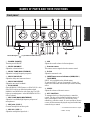
1 POWER (ON/OFF)
Turn the power ON/OFF.
2 MUSIC BALANCE
Adjust the volume balance.*
3 MUSIC TONE (BASS/TREBLE)
Adjust the low/high frequency response.*
4 MIC ECHO DELAY
Adjust the delay time between echoes.*
5 MIC ECHO REPEAT
Adjust the amount of feedback.*
6 ECHO MODE
Select NORMAL, WIDE (stereo) or SPACIOUS** echo.
SPACIOUS echo is an effect that produces both
NORMAL and WIDE echo with a time lag. The LED
lights up in amber/green** when WIDE/SPACIOUS**
echo is selected.
7 MIC TONE (BASS/MID/TREBLE)
Adjust the low/middle/high frequency response of
microphones.*
8 MIC jacks (1/2/3**)
Connect microphones to these jacks.
9 MIC VOL (1/2/3**)
Adjust the microphone input level.*
0 MIC
Adjust the overall volume of all microphones.
A Remote sensor
This sensor receives signals from the remote control.
B ECHO
Adjust the amount of echo.
C INPUT/Input source indicators (DVD/AUX**/
TAPE/BGM)
INPUT is not available in the default setting.
To activate INPUT, refer to “Input mode” on page 14.
Input source indicators indicate the input source currently
active.
D MUSIC
Adjust the volume of the music source.
E KEY CONTROL
To transpose the key of the played music, rotate this
control. The key can be changed in halftone steps in 5
steps; either higher or lower. To reset the key to the
natural key, press this control. If over 4 seconds of silence
occurs, the unit assumes the played song has finished and
resets the key to natural.
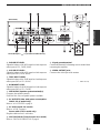
NAMES OF PARTS AND THEIR FUNCTIONS
Front panel
The shaded part ( ) is provided for KMA-700 only.
* Use a flathead screwdriver to adjust.
**KMA-700 only

4 En
NAMES OF PARTS AND THEIR FUNCTIONS
For details on component connection, refer to “SYSTEM
CONNECTIONS” on page 6.
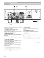
1 BALANCED MIC INPUT jacks (1/2)
Connect microphones to these jacks.
These are balanced inputs and each connects to the same
circuit MIC 1 and 2 on the front panel.
2 DVD audio input jacks
Connect to the output jacks of KARAOKE equipment or
DVD player.
3 AUX audio input jacks*
Connect to the output jacks of a TAPE player, VCR, etc.
4 TAPE audio input jacks
Connect to the output jacks of a TAPE player, VCR, etc.
5 TAPE audio output jacks
Connect to the input jacks of a TAPE player, VCR, etc.
6 BGM audio input jacks
Connect to the output jacks of the source component of
background music.
7 SUBWOOFER jack without low-pass filter
Connect to the input jack of the subwoofer with a low-
pass filter. This jack outputs the monaural signal directly.
8 SUBWOOFER jack with low-pass filter
Connect to the input jack of the subwoofer.
9 PRE OUT jacks
Connect to the input jacks of the extension power
amplifier.
0 IMPEDANCE SELECTOR*
Refer to “IMPEDANCE SELECTOR” on page 7.
A REMOTE jack
Connect to an external remote control.
Refer to “Connecting an external remote control” on page
8.
B VIDEO INPUT jacks
Connect to the input jack of the video output of a DVD,
AUX*, or background video player or video camera, etc.
Rear panel
(Asia model)
The shaded part ( ) is provided for KMA-700 only.
* KMA-700 only

5 En
NAMES OF PARTS AND THEIR FUNCTIONS
PREPARATION
English
C DVD INPUT LEVEL
Adjust the balance of the DVD input level with respect to
other inputs (AUX*, TAPE, BGM).
D AUX INPUT LEVEL*
Adjust the balance of the AUX input level with respect to
other inputs (DVD, TAPE, BGM).
E TAPE INPUT LEVEL
Adjust the balance of the TAPE input level with respect to
other inputs (DVD, AUX*, BGM).
F BGM INPUT LEVEL
Adjust the balance of the BGM input level with respect to
other inputs (DVD, AUX*, TAPE).
G SPEAKERS (Speaker system terminal(s))
Connect to the speaker system(s).
For KMA-500, only one speaker system is available.
H AC OUTLETS (Max. total power consumption:
100 W. U.S.A. model only)
Refer to “AC OUTLETS” on page 9.
I AC IN (Except U.S.A. model)
Refer to “AC IN” on page 9.
Power cable (U.S.A. model only)
Plug this cable into an AC wall outlet.
J VOLTAGE SELECTOR (Except U.S.A. model)
Refer to “VOLTAGE SELECTOR” on page 9.
K Signal ground terminal
Connect this terminal if a humming noise is emitted when
connecting this amplifier.
L VIDEO OUTPUT jacks
Connect to the video input of the monitor.
(Asia model)
The shaded part ( ) is provided for KMA-700 only.
* KMA-700 only

6 En
OPERATION
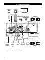
SYSTEM CONNECTIONS
MIC
Monitor TV
MIC
Monitor TV
Monitor TV
System 2
Active subwoofer
System 1
Active subwoofer
(With lowpass filter)
System A
Right Left
(Asia model)
System B
(KMA-700 only)
Right Left
KARAOKE/
DVD player
VTR/LD
player
(KMA-700
only)
Background
music/video
player
Power
amplifier
The shaded part ( ) is provided for KMA-700 only.
TAPE
recorder

7 En
OPERATION
English
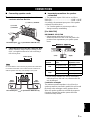
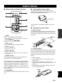
■ Connecting speaker cords
1 Pull the lever up to open, then insert the
conductor wire into the hole.
2 Close the lever to secure the conductor wire.
Before connection, strip a section of coating 15 mm
(9/16”) in length from the end of each cord using a
tool such as pliers.
Be careful that the cord conductors projected from a terminal do
not contact with another cord. Contact from the conductors of
different speaker cords may cause damage to the system.
■ Important precautions for speaker
connection
• The maximum outputs of this unit are as follows:
KMA-700..................................................120 W + 120 W
KMA-500..................................................100 W + 100 W
Accordingly, the maximum input power of the speakers
used must exceed the above.
• Use Yamaha speakers to prevent any trouble or
damage caused by mismatching.
[For KMA-700]
IMPEDANCE SELECTOR
• Before turning on this unit, be sure to set
IMPEDANCE SELECTOR on the rear panel to the
position whose requirements your speaker system
meets.
• Do not change IMPEDANCE SELECTOR setting
while the power to this unit is on, otherwise this unit
may be damaged.
Connection examples
The minimum speaker impedance is 4 Ω. If two 6 Ω
speaker systems are connected in parallel, this will exceed
the design value and trigger a safety protector device.
When two speaker systems are used and the protector is
frequently activated, the speaker systems should be
connected serially instead.
CONNECTIONS
Note
(+) cord to
(+) terminal
(–) cord to (–) terminal
The shaded part ( ) is provided for KMA-700 only.
15 mm (9/16”)
Right
speaker
Left
speaker
The shaded part ( ) is provided for KMA-700 only.
Switch
position
If your system
uses:
Speaker
impedance level
Low
One speaker system
4
Ω or higher
Two speaker systems
8
Ω or higher
High
One speaker system
8
Ω or higher
Two speaker systems
16
Ω or higher
(Low) (High)

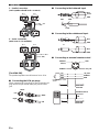
8 En
CONNECTIONS
1. Parallel connection
(each speaker should be 8 Ω or more)
2. Series connection
(total: over 4 Ω is available)
[For KMA-500]
The speaker impedance must be between 8 Ω to 16 Ω.
■ Connecting the RCA pin plugs
When connecting RCA pin plugs, be sure to insert the red
plug into the red jack and the white plug into the white
jack.
■ Connecting to the balanced input
■ Connecting to the unbalanced input
■ Connecting an external remote control
6 Ω 6 Ω
6 Ω + 6 Ω ➝ 3 Ω
(<4 Ω : NG)
6 Ω 6 Ω
6 Ω + 6 Ω = 12 Ω
(>4 Ω : OK)
Left
Right
White
Red
White
Red
HOT
COLD
GND
HOT
COLD
GND
HOT
GND
HOT
GND
or
GND
+5V_OUT
REMOTE
(Direct)
REMOTE
+5V
OUT
GND
+5V_OUT
REMOTE
GND
External remote control
satellite
RMC KMA-700/
KMA-500
REMOTE (Direct)
GND
RMC KMA-700/
KMA-500

9 En
CONNECTIONS
OPERATION
English
1. External remote control satellite
Connect to +5V_OUT, REMOTE and GND.
By connecting the remote control satellite to this input, this unit
can receive the signal of the remote control.
2. REMOTE (Direct)
Connect to REMOTE (Direct) and GND.
Connect to the infrared diode output (open collector) of
RMC.
By connecting the REMOTE (Direct) to this input, this unit can
receive the signal of the REMOTE.
■ Power related switch and connections
on the rear panel
The shaded part ( ) is provided for KMA-700 only.
The parts in the sub illustrations are provided for U.S.A.
model only.
AC IN
(Except U.S.A. model)
Connect the supplied power cable to AC IN.
Power cable
Plug the power cable into the AC wall outlet after all other
connections are complete.
VOLTAGE SELECTOR
(Except U.S.A. model)
VOLTAGE SELECTOR on the rear panel of this unit
must be set for your local main voltage BEFORE plugging
the power cable into the AC wall outlet.
AC OUTLETS
(SWITCHED. U.S.A. model only)
Use these outlets to connect the power cables from your
other components to this unit. The power to AC
OUTLETS is controlled by POWER on the front panel of
this unit. The outlets supply power to any connected
component whenever the power of this unit is turned on.
Total power consumption is 100 W.
• Be careful that the total power consumption does not exceed the
wattage marked on the rear panel. Do not connect appliances
other than system components to the power outlets of this unit.
• Do not connect a TV set to this unit; even if it indicates a power
consumption value below the permissible value when the TV
power is turned on.
Note
Note
(Asia model)
Supplied power cable
(Except U.S.A. model)
Notes

10 En
* KMA-700 only
**Balanced input, on the rear panel
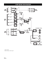
CONFIGURATION DIAGRAM

11 En
OPERATION
English
■ Names of parts and their functions
1 INPUT
INPUT is not available in default setting.
To activate INPUT, refer to “Input mode” on page 14.
2 KEY CONTROL ( / / )
Transpose the key of the played music.
3 MIC ( / )*
Adjust the overall volume of the microphones.
4 ECHO ( / )*
Adjust the amount of echo.
5 MUSIC ( / )*
Adjust the music volume.
* The LED on the corresponding control on the front panel blinks
during adjustment.
6 PRESET (1/2/3)
Recall saved preset settings for MIC volume/ECHO
amount/MUSIC volume/ECHO MODE.
To save current settings of the above, press the desired
button (PRESET 1, 2, 3 or KEY CONTROL on the front
panel) for 3 seconds. Pressing KEY CONTROL saves
settings to PRESET 1. When save is completed, “ ” on
the KEY CONTROL blinks once. You can save up to 3
presets (PRESET 1/2/3) on this unit. Refer to “Power ON
recall” on page 14.
7 ECHO MODE
Select NORMAL, WIDE or SPACIOUS (KMA-700 only)
echo.
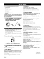
■ Preparing the remote control
The remote control comes with the battery already
installed. Before using the remote control for the very first
time, pull out the plastic tab, as shown.
For information on replacing the battery, refer to next
section.
■ Operation of remote control
1. Remote control
The distance between the remote control and the remote
sensor of this unit should be within 6 m (20’). Be sure to
aim the remote control directly at the remote sensor on the
front panel.
2. Loading a battery
The life of the battery used in the remote control is about
half a year under normal use. Remove the battery if the
remote control is not used for an extended period. When
the battery becomes weak, replace with a new CR2025
battery.
To replace the battery:
1. Using a small screwdriver, carefully slide out the
battery holder.
2. Remove the expired battery, and place the new
CR2025 battery onto the battery holder with the + side
facing up.
3. Slide the battery holder into the remote control, and
push it so that it clicks shut.
REMOTE CONTROL
Plastic tab
Within 6 m
(20’)
30°
30°
+ side up

12 En
REMOTE CONTROL
Improper use of batteries may cause a risk of battery
leakage and explosion.
Adhere to the following guidelines:
• Do not attempt to recharge the old battery.
• Insert a battery so that the positive (+) and negative (–)
poles are positioned as shown.
• Even if the shapes are the same, the voltage of batteries
may vary depending on the models. Be careful not to
use different model of battery.
• Dispose of the old battery in accordance with local
regulations.
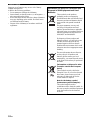
Information for Users on Collection and
Disposal of Old Equipment and Used
Batteries
These symbols on the products,
packaging, and/or accompanying
documents mean that used electrical and
electronic products and batteries should
not be mixed with general household
waste.
For proper treatment, recovery and
recycling of old products and used
batteries, please take them to applicable
collection points, in accordance with your
national legislation and the Directives
2002/96/EC and 2006/66/EC.
By disposing of these products and
batteries correctly, you will help to save
valuable resources and prevent any
potential negative effects on human
health and the environment which could
otherwise arise from inappropriate waste
handling.
For more information about collection
and recycling of old products and
batteries, please contact your local
municipality, your waste disposal service
or the point of sale where you purchased
the items.
[Information on Disposal in other
Countries outside the European
Union]
These symbols are only valid in the
European Union. If you wish to discard
these items, please contact your local
authorities or dealer and ask for the
correct method of disposal.
Note for the battery symbol
(bottom two symbol examples):
This symbol might be used in
combination with a chemical symbol. In
this case it complies with the requirement
set by the Directive for the chemical
involved.

13 En
OPERATION
English
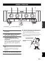
1 Connect the required number of
microphones.
2 Set the POWER switches of this unit and
other required components to ON.
3 Play the KARAOKE music source
component, and adjust the volume by
rotating MUSIC.
The music source is selected automatically in default
setting. To set the conditions for selection, refer to
“Auto input condition” on page 14. To select the
music source manually, refer to “Input mode” on
page 14.
4 Adjust the microphone volume by rotating
MIC.
When different microphone volumes are not
balanced, adjust MIC VOL using a flathead
screwdriver.
5 Adjust the ECHO amount by rotating ECHO.
6 Adjust the key by rotating KEY CONTROL.
■ Notes for the proper use of microphones
• Sing into the microphone by holding it at a distance of 5 to
10 cm (2 to 3-15/16”) from your mouth.
• To ensure clear sound, grasp the microphone below the mic
head.
• Do not block the lower part of the windscreen. This will disturb
proper voice reproduction with unclear bass. Howling also
tends to occur in such cases.
GENERAL OPERATION
The shaded part ( ) is provided for KMA-700 only.
5 to 10 cm (2 to 3-15/16”)
away from your mouth.
Grasp the microphone below
the head.

14 En
You can set the following menu in Setup mode:
• Power ON recall
• Input mode
• Auto input condition
•Enable remote
• Remote mode
• MIC/MUSIC max level
• MIC/MUSIC volume select
• Initializing
To set each menu above, set the corresponding controls as
shown in the “Setup mode table” on page 15 according to
the following procedure.
1 To enter Setup mode, turn off the main unit
and press POWER while pressing KEY
CONTROL and ECHO MODE.
2 Set KEY CONTROL and MUSIC according to
the “Setup mode table” on page 15 to set
desired menus and items.
For Auto input condition, select the desired source
before selecting the item.
Set all settings you want to change before moving to
step 3.
3 Press KEY CONTROL to enter the settings.
“ ” blinks once when the settings are entered.
4 To terminate Setup mode, turn off the main
unit.
■ Menus in Setup mode
1. Power ON recall
Select Last memory or Preset, to recall the settings of MIC
volume/ECHO amount/MUSIC volume/ECHO MODE
when the unit is turned on.
Last memory*: The settings when the unit was turned off
last are recalled.
Preset: The settings saved to PRESET 1 are recalled.
2. Input mode
Set Input mode to Auto or Manual.
Auto*: The input source is set automatically.
Manual: The input source is selected by INPUT.
Source is selected in order of DVD, AUX**, TAPE,
BGM.
3. Auto input condition
Set the conditions for each source (DVD, AUX** and
TAPE) for Auto Input mode described in 2.
Audio*: The source is switched based on audio signal.
Video: The source is switched based on video signal.
Audio/Video: The source is switched based on audio or
video signal.
For only this menu, select desired source by INPUT
before selecting the desired item.
4. Enable remote
Enable or disable remote control.
Enable*: The remote control is enabled.
Disable: The remote control is disabled.
5. Remote mode
Set the light receiving device.
Front&Ext.*: Both the front panel and external remote
control satellite receive the signal from the remote control.
Front: Only the front panel receives the signal.
Ext.: Only the external remote control satellite receives
the signal.
6. MIC/MUSIC max level
Set the maximum volume of MIC and MUSIC.
10*: No setting.
9 to 3: The maximum volume is set to the level indicated
(2 to 0 cannot be set).
7. MIC/MUSIC volume select
Select how MIC and MUSIC volumes increase/decrease
(i.e., the volume curve) when the controls are turned.
Pattern 1*: Steep curve
Pattern 2: Less steep curve
Pattern 3: Least steep curve, and is most suitable for fine
adjustment.
8. Initializing
Reset all the settings set in Setup mode to the defaults.
Cancel: Initializing is not executed.
Initialize: Initializing is executed.
When pressing KEY CONTROL with MUSIC set to 3,
Initializing is executed.
SETUP MODE
* Default setting
**KMA-700 only

15 En
SETUP MODE
OPERATION
English
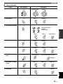
■ Setup mode table
Menu KEY CONTROL Items/MUSIC
1. Power ON recall
2. Input mode
3. Auto input condition
4. Enable remote
5. Remote mode
6. MIC/MUSIC max
level
7. MIC/MUSIC volume
select
8. Initializing
+1 Last memory: 1 Preset: 2
+2 Auto: 1 Manual: 2
+3
Audio: 1 Video: 2 Audio/Video: 3
Select desired source
by INPUT.
Example: DVD
+4 Enable: 1 Disable: 2
+5 Front&Ext.: 1 Front: 2 Ext.: 3
–1
No setting: 10 Set to the indicated level: 9 to 3
Example: 3
–2
Pattern 1: 1 Pattern 2: 2 Pattern 3: 3
–5
Cancel: 1 Initialize: 3

16 En
ADDITIONAL INFORMATION
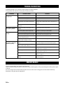
If problems should occur, check the following table for simple remedies.
If the problem still cannot be solved, please consult your dealer.
When the set gets dirty, wipe it with a soft, dry cloth.
Never use alcohol, thinner, benzene, insecticide or other volatile agents, for they may damage the surface paint or gloss
of the set.
Also do not wipe the set with a chemical cloth or leave it on the set for a long period, for the surface finish may
deteriorate or the paint may be stripped off.
TROUBLESHOOTING
Problems Possible causes Solutions
No speaker sound is
output at all.
POWER is set to OFF. Set POWER to ON.
The power cable is unplugged. Plug the power cable securely into the AC wall outlet.
MUSIC is in the lowest position. Adjust MUSIC.
The wrong music source is selected when
Input mode is set to Manual in Setup mode.
Select the correct music source with INPUT or set Input
mode to Auto in Setup mode. Refer to “Input mode” on
page 14.
The sound is cut off due to a temperature rise
in the unit.
Turn the power off, then leave the unit alone for cooling.
No sound is output from
one of the speakers.
MUSIC BALANCE is turned fully to one
speaker.
Set the control to the center position.
One of the speaker cords is disconnected. Insert the cord securely into the terminals.
No microphone sound is
output.
The microphone plug is not fully inserted. Insert the plug securely into the jack.
The switch on the microphone is set to OFF. Set the switch on the microphone to ON.
The corresponding MIC VOL or MIC controls
are in the minimum position.
Adjust the control.
The microphone is too far from your mouth, or
the microphone handling is incorrect.
Refer to the user’s manual supplied with your microphone.
The remote control does
not work, or does not
function properly.
The remote control is too far away or tilted too
much.
The remote control will function within 6 m (20’) and no
more than 30 degrees off-center from the front panel.
Direct sunlight or lighting is striking the
remote control sensor of this unit.
Reposition this unit.
Enable remote is set to Disable in Setup mode. Set Enable remote to Enable in Setup mode. Refer to
“Enable remote” on page 14.
The wrong Remote mode is set in Setup mode. Set the correct Remote mode in Setup mode. Refer to
“Remote mode” on page 14.
The battery is weak. Replace with a new CR2025 battery. Refer to “Loading a
battery” on page 11.
When INPUT does not work, Input mode is set
to Auto.
Set Input mode to Manual in Setup mode. Refer to “Input
mode” on page 14.
MAINTENANCE
Page is loading ...
Page is loading ...
Page is loading ...
-
 1
1
-
 2
2
-
 3
3
-
 4
4
-
 5
5
-
 6
6
-
 7
7
-
 8
8
-
 9
9
-
 10
10
-
 11
11
-
 12
12
-
 13
13
-
 14
14
-
 15
15
-
 16
16
-
 17
17
-
 18
18
-
 19
19
-
 20
20
-
 21
21
-
 22
22
-
 23
23


Yamaha KMA-700 Owner's manual
- Type
- Owner's manual
- This manual is also suitable for
Ask a question and I''ll find the answer in the document
Finding information in a document is now easier with AI
Related papers
Other documents
-
VocoPro DA-8900 User manual
-
 Free The Tone FM-1V Fire Mist Overdrive User guide
-
Better Music Builder G5 Series Owner's manual
-
 Audio2000's AKJ7404 User manual
-
-
-
King KMA 20 Installation guide
-
-
Honeywell KMA 29 User manual
-
Kicker 2018 KMA Mono Amplifier Owner's manual

