Page is loading ...

Dynalink ADSL2+ Modem Router
Quick Setup Guide
– RTA1320 (Single Ethernet & USB)
– RTA1030W (Single Ethernet & USB with Wireless)
– RTA1025W (4-Ethernet ports & USB with Wireless)
– RTA1046VW (4-Ethernet ports with Wireless & VoIP)

ADSL 2+ Modem Router Quick Set-up Guide
Important
This Guide is intended to get you started quickly. We have made the factory
default setting of this router suitable for your country
1
. All you need is to
follow through the steps we describe here.
This Guide should be read in conjunction with the User Manual
2
.
It is provided as a PDF file on this CD. You can view or print this User
Manual.
Advanced users, or those who have other setup preferences such as USB
install should also refer to the relevant sections of the User Manual.
Notes for this page:
1. In Australia the majority of ADSL subscribers get PPPoE service by
default. In New Zealand the majority of ADSL subscribers get PPPoA
service by default. Your router is already preset to meet this requirement.
2. In the User Manual please ignore all references to the value
of VPI or VCI. In Australia VPI is 8 and VCI is 35, In New Zealand VPI is 0
and VCI is 100. These numbers are preset as factory default. Do not
change them.
1
Do I need a micro filter?
Microfilters filter out ADSL signals to allow ADSL and regular voice calls
simultaneously over a single telephone line.
Any equipment sharing an ADSL telephone line, other than an ADSL modem,
must be connected to a telephone jackpoint via a microfilter. Examples
include telephone headsets, fax machines, dial-up modems and set top boxes
(eg Foxtel Digital).
A quality microfilter/splitter featuring two jacks (ADSL/MODEM and PHONE) is
recommended for performance and convenience. A suitable Dynalink microfilter/
splitter can be purchased from your local computer store or your service provider.

2
Before you start
Your computer must have:
• Ethernet port (or USB for models RTA1320, RTA1030W, RTA1025W)
• TCP/IP protocol enabled
• A web browser, such as Internet Explorer 5.x, Firefox 1.x or better.
Obtain your Internet account information from your ISP:
• Login user name and password
• Public IP address (only if you subscribe for static IP)
• DNS server IP (only if specified by ISP).
Connection options:
1. Ethernet (Recommended - this option is Operating System independent.)
The modem router comes with single Ethernet port (RTA1320 & RTA1030W),
or a built in 4-port switch (RTA1025W & RTA1046VW). If you require more
ports, purchase a network switch to provide for more connections, or use
wireless (see the next option). Only one Ethernet cable is provided. Extra
cables and network switch can be purchased from your supplier.
2. Wireless LAN (Only for computers that support wireless LAN. This option
is also Operating System independent.)
The router is also a wireless access point that supports IEEE 802.11g and
802.11b standards. To configure for wireless it is best to connect to a
computer via Ethernet and then follow the Setup Procedure under Section
6 Setting up wireless. Model RTA1320 does not have this option.
3. USB (Not recommended - this option is intended for a standalone
Windows Vista/XP/2000/ME/98SE computer only)
Choose this option only if a computer does not have an Ethernet port and it
is not feasible to add an Ethernet port or use wireless. You must then
install a driver to operate the router. The USB driver and detailed
installation instructions (in the User Manual) are located on the enclosed
CD. Model RTA1046VW does not have this option.

ADSL 2+ Modem Router Quick Set-up Guide
Connecting the modem router
1. Connect the DSL port of the modem directly into your ADSL jackpoint
(telephone wall socket) with the provided line cord. If connecting through
a filter, the filter must have a designated ADSL/MODEM port for bypassing
filtering of ADSL signals.
2. Connect the Ethernet port of each computer to Ethernet/LAN port of the
router. One Ethernet cable is provided.
Note: If you choose to connect via the USB port (not recommended), there
is no need to use the Ethernet cable. Do not plug in the USB cable yet.
During driver installation, you will be advised to do so. Refer to the User
Manual for instructions.
3. Connect the provided AC/AC power adaptor to the Power jack of the router.
Plug the adaptor into a mains power outlet. Switch on the router. In normal
operation the following lights should be on: Power, DSL, Ethernet/LAN
(1, 2, 3 or 4 if using 4-port models), WLAN (wireless models only). Section
10 of this Guide explains how these indicator lights work.
3
Getting the computer ready
You have two options. Option (1) is recommended and is the Windows
default network setting.
1. Obtain an IP address automatically
Most computers are already configured this way. By default the router
is a DHCP server which automatically assigns an IP address to a computer
that is connected to it. Now go to Section 5 – Going On-Line.
If you are unsure of your computer’s network configuration, refer to Q1-6
in Section 11 – Troubleshooting.
2. Assign an IP address manually
The router’s default address is 192.168.1.1. If you prefer to assign an IP
address manually to your computer, use 192.168.1.x (x is a number
between 2 and 254).
4

5
Windows XP/2000:
1. Go to Control Panel – Network
Connections. Open Local Area
Connections and click Properties.
Double click Internet Protocol (TCP/IP).
Select Use the following IP address.
2. Enter 192.168.1.x (x is a number you
pick between 2 and 254). This is the IP
address you assign to the computer.
Subnet Mask is 255.255.255.0.
3. Enter the router’s IP 192.168.1.1 as
Default gateway, and as Preferred DNS
server If your ISP specifies DNS server
addresses, enter the specified addresses according to the ISP’s instructions.
4. Click OK to finish.
You have now finished with configuring your computer. Go to the next section
for going on-line.
Going on-line
Step 1 GO TO THE ‘CONNECT TO INTERNET’ PAGE
Start your web browser (Internet Explorer, Firefox,
etc). Enter the default address http://192.168.1.1.
Type admin for both User name and Password.
See Q1 in Section 11 - Troubleshooting if you
cannot get this screen.
Next you will be in the Quick Start > Connect to
Internet page.
Step 2 ENTER INTERNET ACCOUNT DETAILS
Enter your Internet account User Name & Password in the exact format
as specified by the ISP. Typically the User name resembles an e-mail address
with the suffix “@isp.com.au”. Make sure the page displays “Your DSL router
is ready to connect” before clicking Connect.

ADSL 2+ Modem Router Quick Set-up Guide
See Q2 in Section 11 – Troubleshooting, if after several minutes the message
“Your DSL router is not ready to connect” still shows.
Once connected the screen changes to displaying on-line time. The PPP light
on the front panel of the router will come on, indicating that you are online.
Click Disconnect only if you wish to disconnect manually.
You are now successfully connected to the Internet. Your Internet account user
name & password will be saved automatically.
If previously the computer had a dial-up modem for Internet connection, check your
browser setting. The system may still try to communicate through the previous
connection. In Internet Explorer, go to
Tools–Internet options–Connections
,
select
Never dial a connection
. Close Internet Explorer to take effect.

6
Setting up Wireless
Models RTA1025W, RTA1030W and RTA1046VW only
A full description on this topic is found in the User Manual for each model.
Wireless support is enabled by default. The router is a wireless access point.
IEEE 802.11g and 802.11b wireless network standards are supported. For indoor
operations, these standards provide typically 20m and 60m range
respectively.
Wireless security features are disabled for ease of initial install. It is important
to enable wireless security to protect your network after you have verified that
all wireless computers can connect.
6.1 SET UP PROCEDURE
1. Connect via Ethernet or wirelessly from a computer to configure for
wireless operation. Start your web browser. Enter the default address
http://192.168.1.1. Username and Password are both admin.
(This is also described in Step 1, Section 5 – Going On-line)
2. Go to Wireless > Basic settings. You may choose your own SSID, or use
the unique factory default SSID. Wireless computers scan all channels
and once connected, use the same channel as the access point. Note:
if interference with another nearby wireless network is detected, select
a different channel.
3. Set up wireless computers according to the vendor’s instructions. Because
the router is a wireless access point, select infrastructure mode. Do not
use Adhoc (peer-to-peer) mode.
To verify that a wireless computer is connected, go to Status > Wireless
Clients. The table displays the hardware MAC addresses of all connected
wireless computers.
6.2 SET UP WIRELESS SECURITY
It is essential to protect your network by enabling wireless security. Go to
Wireless > Security. Select ‘WPA-PSK’ and then choose ‘TKIP’ or ‘AES’ for
‘Data Encryption’. AES is generally accepted as better than TKIP, and is much
more secure than the outdated WEP encryption. Please make sure your wireless
computer also supports the same encryption type.

ADSL 2+ Modem Router Quick Set-up Guide
Next, enter your choice of ‘password’ into the Pre-Shared Key: box. Any
printable characters may be used. Good practice is to use a strong password of
random characters and is over 20 characters long. Click Apply to take effect.
The same key must be entered into your computer when you attempt to connect
wirelessly. Refer to the vendor’s instructions of your computer or wireless
adaptor for details. Usually the process is like this:
• Click on a wireless icon at the right hand bottom corner of your desktop.
• Select your wireless router from a list of wireless networks available. Your
wireless router is identifiable by its SSID.
• Windows will ask for a “Network Key”. Enter the Pre-Shared Key you have
chosen for the router.

7
Voice over IP
Model RTA1046VW only
VoIP (Voice over IP) is a voice service provided over the internet by some service
providers. It allows users to talk without using a conventional telephone service
and often provides lower call costs.
A full description on this topic is found on Chapter 4: Web Configuration > Voice
over IP on page 117 of the User Manual.
7.1 CONNECTING THE HARDWARE
1. Connect a telephone handset to Phone1 port.
2. Connect the PSTN port to the Phone port of your microfilter/splitter.
3. Connect the DSL port to the Modem port of your microfilter/splitter.
4. Plug the microfilter into the telephone wall outlet.
Note:
A: Handsets are not provided. Any standard telephone handsets may be used.
B: Microfilters/splitters can be purchased separately. To use your VoIP Service without a microfilter/
splitter, connect the DSL port directly to the telephone wall outlet. However, with this configuration
you cannot use the RTA1046VW for PSTN calls (conventional telephone service).

ADSL 2+ Modem Router Quick Set-up Guide
7.2 CONFIGURING THE VOIP SETTINGS
The router supports only SIP (Session Initiation Protocol) protocol for Internet
telephony. It is necessary to subscribe and receive the settings required from
your VoIP service provider in order to set up VoIP service.
The settings required are specific to your VoIP provider. Before you start,
make sure you have received appropriate settings from your service provider.
Go to Voice > SIP Basic. Example settings:
Australian Users should choose pppoe_8_35_1 (or pppoa_8_35_1).
New Zealand Users should choose pppoa_0_100_1.
SIP Transport Protocol: Specify UDP
(default) or TCP as required by the
service provider.
SIP Transport Port: Enter the port
number of the SIP proxy server if
specified by the service provider.
Default is 5060.
SIP Registrar Address: Enter the
Domain Name or IP and the port
required for the service.
SIP Outbound Proxy: Enter the Domain Name or IP and the port required for
the service.
SIP Proxy Server Address: Enter the Domain Name or IP and the port required
for the service.
Registration Information: Enter your SIP account details. If using two accounts,
enter the account details that correspond to Phone1 and Phone2. Click Apply.
The VoIP Ready indicator light will change to green upon successful registration
with your VoIP provider.
Warning: Note that the dial tone for VoIP calls will be slightly different when
compared to standard telephone line dial tone. Ensure you are aware of the
difference so you can be sure you are making low cost VoIP calls rather than
more expensive PSTN calls (conventional telephone service).
Other advanced VoIP functions and settings are optional. A full description on
this topic is found on Chapter 4: Web Configuration > Voice over IP on page 117
of the User Manual.

Advanced functions
8.1 FIREWALL & TRAFFIC RESTRICTIONS
Default firewall configuration
By default the firewall blocks all inbound requests including Ping from the
Internet to your local network. In the outbound direction, all traffic that originates
from your local network are allowed. Most users do not require changing any
firewall settings and are automatically protected by this default configuration.
Running a server on your local network
If you want Internet users to have access to servers on your local network, set up
Port Forwarding (Virtual Servers) to allow incoming requests reaching the
servers. Refer to the Virtual Server Port Forwarding section of the User Manual.
DMZ
If you run applications that require unrestricted 2-way traffic between a
computer on your network and the Internet, set up the computer as DMZ Host.
Refer to the Virtual Server DMZ Host section of the User Manual. Caution: the
specified computer will no longer be protected by the firewall.
Restricting access
You can block specified computers on your network to access the Internet by
defining IP Filters. Refer to the Firewall IP Filtering section of the User Manual.
8.2 IP EXTENSION (HALF-BRIDGING)
The ADSL router can be made to
resemble a bridge modem. It bridges
traffic between the Internet (WAN) and
your local network (LAN). In this mode
firewall and Internet sharing (NAT) are
disabled. A computer or network
device connected directly to the
modem receives a WAN IP from your
ISP via the bridged modem. This
arrangement is suitable for certain applications that require a computer or
a network device, such as a VPN router, to receive a WAN IP.
Caution: This mode of operation disables the firewall and assumes security will
be provided by another device on your LAN.
8

ADSL 2+ Modem Router Quick Set-up Guide
To set IP extension, go to the Advanced menu. Select WAN > Internet. Click on
the “modify icon” under Edit:
The next screen displays VPI/VCI as 8/35 (Australia) or 0/100 (New Zealand).
Do not change these numbers. Go Next. Select PPPoE LLC (Australia) or PPPoA
VCMUX (New Zealand). Go Next. On the next screen untick Enable NAT, and
tick PPP IP extension as illustrated. Go Next.
Enter your Internet account user name and password. Go Next. The new
configuration is displayed. Click Apply to confirm changes. The router will
restart itself to activate IP extension mode.
NAT or firewall settings disappear from the Advanced menu hereafter. Now
follow Step 2 of Section 5 – Going On-line.
Please refer to the User Manual for other advanced functions. Always restart
the router to activate any changes to configuration.

9
Tips for security
This router is shipped “secure” with firewall enabled by default. In order to
take full benefit from the security features of this router:
Do:
• Change your router’s administrative user name & password.
• Back up your router’s configuration. This function can be found in the
router’s Management > Backup Config menu.
• Disable UPnP if you don’t need this function.
• Read about the more advanced functions. They can be found in the
User Manual for each of the models.
Don’t:
• Enable remote access to the router, unless you are confident in handling
the security implications.
• Enable IP extension (half-bridging) without any other firewall protection.
If the router operating in this mode is connected to a computer, to the
minimum install a “personal firewall” (software) to protect the computer.
• Send your router away for repair or replacement without resetting to
factory default or wiping out your Internet account login details. Use the
Backup Configuration option to store your router’s setting elsewhere. This
function can be found in the router’s Management > Backup Config menu.
When a replacement unit is received, restore the original setting from the
backup file.
WIRELESS SECURITY
A number of wireless security features are supported.
Protected access
To enable wireless security, go to Wireless > Security. Available options are:
WEP, 802.1x, WPA, WPA2.

ADSL 2+ Modem Router Quick Set-up Guide
Advanced security is provided by WPA/WPA2 and 802.1x. These are robust
security mechanisms. A special “home mode” known as WPA-PSK is
recommended for most users. You choose a password, known as Pre-Shared
Key or PSK, for the wireless network. Please refer to Section 6.2 of this Guide
for setting up.
WEP offers basic protection from eavesdropping. When enabled, all wireless
stations transmit data encrypted using a predetermined key. WEP is outdated
and is mainly used for backward compatibility with legacy equipment.
Whichever protection method is selected at the access point, all wireless clients
must also support the same method in order to connect.
Access Control
This allows access control via a list of wireless stations by registering the MAC
address of permitted clients at the access point. Go to Wireless > Access
Control and follow the instructions. For detail procedure, refer to the User
Manual.
Hide SSID
SSID is a name given to an access point to identify the network. Users may
change SSID anytime. By default, SSID is periodically broadcasted by the
access point to advertise its presence. In enabling the Wireless > Basic > Hide
Wireless Network option, SSID is not broadcasted. Other wireless users
normally cannot see the access point.

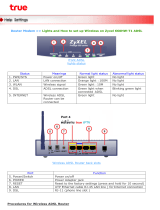
Function Color and Status Definition
Power
Off Power is off
Solid Green Power is on and the device operates normally
Solid Red
Power on self-test in progress
The device enters the console mode
of the boot loader
Power on self-test failure if this light
remains solid
Flashing Red Firmware upgrade in progress
DSL
Off No DSL signal
Slow Flashing Green DSL line handshaking in progress
Fast Flashing Green DSL line training in progress
Solid Green DSL link is up
PPP
Off Modem is not online
Solid Green Modem is online
Ethernet/
LAN 1 to 4
Off No Ethernet signal
Flashing Green Data going through port
Solid Green Ethernet is connected
RTA1320, RTA1025W and RTA1030W only
USB
Off No USB signal
Flashing Green Data going through port
Solid Green USB is connected
RTA1025W, RTA1030W and RTA1046VW only
WLAN
Off Wireless is disabled
Flashing Green Data going through wireless
Solid Green Wireless is ready
RTA1046VW only
Phone 1 or 2
Off Handset on hook/ in PSTN mode
Solid Green VoIP in use
VoIP ready
Off VoIP service is not ready
Solid Green VoIP service is ready
Indicator lights
10

ADSL 2+ Modem Router Quick Set-up Guide
Troubleshooting Q & A
Q1. Cannot display page to enter Internet user name & password?
1. If previously the computer had a dialup modem, check browser setting. For
example in Internet Explorer, go to Tools–Internet options–Connections,
and select Never dial a connection. Check LAN Settings that the option
Use a Proxy Server is not selected.
2. Check that the router’s ETHERNET light is on. If not, check your Ethernet
cable is firmly plugged in.
3. Perform a PING test. In Windows XP or 2000, click Start-Run. Enter cmd
then OK. Type ping 192.168.1.1 then press Enter. The response should be:
Pinging 192.168.1.1 with 32 bytes of data:
Reply from 192.168.1.1: bytes=32 time=4ms TTL=30
If there is a similar response, the router is communicating with your
computer correctly and the problem lies elsewhere. If the result is
Request timed out, there may be a network problem. Check that the
ETHERNET cable is firmly plugged in.
4. Disable any personal firewall or virus checker temporarily. If you use
Internet Explorer, go to Tools–Internet options-Security. Reset security
level of all 4 icons to default. (You can revert to your customised settings
after configuring the router).
5. If the router is connected to a network hub, try connecting the router
directly to the computer to eliminate any possible problem associated with
the hub.
6. Check that your Computer is set to obtain its IP address automatically.
Go to Start-Run, type ncpa.cpl and press enter.
Right cilck Local Area Connection > Properties > Internet Protocol (TCP/
IP)-Properties. Select Obtain IP address automatically and Obtain DNS
servers automatically. Click OK, then OK to exit.
Q2. Cannot connect to Internet or cannot browse web pages?
• If the DSL light is off
This means the broadband service may not have been activated on your
telephone line. Check that the ADSL Line Filter has been connected
correctly. If it has, contact ISP to confirm that the broadband service
has been provisioned. It is impossible to go online if the DSL light is off,
or keeps flashing all the time.
11

• If the DSL light is on but the PPP light is off
This means the modem is unable to go online because the Internet
username or password you entered as described in Section 5 – Going On-
line is incorrect, or the Internet account has not been activated. Check that
you have entered your Internet user name and password in the exact
format as specified by ISP. Repeat entry if necessary. Should this problem
persist, check with your ISP that the Internet account, username &
password are correct, and that your account has been activated.
• If both DSL and PPP light are on
The modem is actually on line. This problem may be with your browser
setting. Try returning any custom settings of the browser to default. If you
have a personal firewall, disable it to see if it makes any difference.
If you still cannot browse, perform a PING test as described in Q1-3, using these
addresses:
(A) Ping www.dynalink.com.au (or any valid web address)
(B) Ping 203.26.24.112 (or any valid public IP address)
If both (A) & (B) reported “request time out”, there is an issue on your local
network, your computer is not communicating to the modem correctly due to
either hardware issues or network misconfiguration.
If (A) failed but (B) yielded responses, this is a DNS server problem. Ask your
ISP if you must enter the DNS server address manually. Follow Q1-6, change the
Obtain DNS servers automatically option to Use the following DNS server
addresses. Enter the DNS server address provided by your ISP.
Q3. Browsing is fine but how can I run certain on-line applications?
You need to set up virtual servers or DMZ host. See Section 8 on Firewall &
traffic restrictions.
Q4. How to reset router if its IP and/or administrative password have been
changed but forgotten?
Reset the router to factory default by pushing a pin into the hidden reset button
located next to the push button at the back of the unit. Push and hold for at
least 5 seconds then release to trigger reset.

ADSL 2+ Modem Router Quick Set-up Guide
Q5. What is the assigned WAN IP when the router is on line?
Go to Status > Internet Connection, the WAN IP is displayed here.
Q.6 How to get information update?
This Quick Guide and User’s Manual on CD are the primary source of information
about the product. Please check the Dynalink website http://www.dynalink.
com.au or http://www.dynalink.co.nz regularly for updates, links, or to
download a more current version of this Quick Set-up Guide.

Default Configuration
This router is shipped with the following factory default settings depending on
your region.
Router IP address 192.168.1.1
Subnet mask 255.255.255.0
VPI/VCI 8/35 (Australia)
0/100 (New Zealand)
Connect mode PPPoE LLC/SNAP (Australia)
PPPoA VC-MUX (New Zealand)
NAT enabled
DSL line mode ADSL2+ (Australia)
G.DMT (New Zealand)
WAN IP dynamic
DHCP enabled
DNS relay on
UPnP IGD enabled
Firewall
Incoming requests blocked
Outgoing traffic not blocked
Configuration & management:
User name admin
Password admin
Telnet password admin
Wireless Settings (not applicable to model RTA1320):
Wireless Channel 11
Wireless security disabled
VoIP settings (RTA1046VW only):
Default SIP port TCP 5060
Default CODEC Auto switching (G.711, G.726, G.729)
12

Warranty
How to get help
Dynalink warrants this product against defects in materials and workmanship
for a period of twelve months from the original date of purchase. We will, at our
discretion, repair or replace the faulty unit, free of charge, provided it is
returned to us with proof of purchase from an authorised dealer within the
warranty period. Return delivery after repair will be paid for by Dynalink. We
reserve the right not to repair or replace goods that:
have been mishandled, abused or not installed according
to the guidelines as outlined in the instructions.
have been subjected to a power surge from other
equipment or other external factors.
have been altered or modified.
If you were unable to progress your installation to the step where you enter
your Internet username and password, contact Dynalink to log a request for
telephone support. Please make sure you provide your full telephone number
including area code or mobile number.
If possible, visit Dynalink’s on-line support area at
http://www.dynalink.com.au/support (Australia)
http://www.dynalink.co.nz/support (New Zealand)
or send e-mail to
[email protected] (Australia)
[email protected] (New Zealand)
Dynalink Technical Support (Australia):
Phone 1800 653 962
Fax 1800 063 962
(Monday-Friday: 9:00am-5:00pm)
Dynalink Technical Support (New Zealand):
Phone 0800 653 962
Fax 09 448 5549
(Monday-Friday: 8:30am-7:30pm)
/