Page is loading ...

Comfort-Set
®
90 Series
TM
PREMIUM
1F97-391
Installation and
Operating Instructions
Retain for Future Use
Thermostat/Humidifier Control
Digital 7 Day Programmable

17
16
4
3
5
6
2
1
7 8
9
10
11
12
13
14
15
Easy, Menu-Driven Set-Up
and Programming
Premium options
to customize the thermostat
to fit your application.

1
INTRODUCTION
Thank you for purchasing your
new Comfort-Set 90 thermostat
and humidifier control. White-
Rodgers has been producing
energy saving controls for over
60 years. We have been design-
ing and producing the Comfort-
Set family of electronic pro-
grammable thermostats since
1982. Comfort-Set 90 is the
third generation of the elec-
tronic programmable family.
We believe you will find that
the Comfort-Set 90 is the most
user friendly and technologi-
cally advanced thermostat and
humidifier control available
today.
Introduction
Installation/Configuration
Programming
FAQs
Features
You will find information about
thermostat buttons and display
beginning on page 2.
Introduction . . . . . . . . . . . . . . . . . . . . . . . . . .1
Installation/Configuration . . . . . . . . . . . . . . .4
Manual Operation and Programming . . . .24
Features . . . . . . . . . . . . . . . . . . . . . . . . . . . . .30
FAQs . . . . . . . . . . . . . . . . . . . . . . . . . . . . . . . .38
Troubleshooting . . . . . . . . . . . . . . . . . . . . . .42
Index . . . . . . . . . . . . . . . . . . . . . . . . . . . . . . .46
Use the tabs at the bottom of the page to quickly
locate sections
Troubleshooting Index

2
THE THE
THE THE
THE
THERMOSTTHERMOST
THERMOSTTHERMOST
THERMOST
AA
AA
A
T BT B
T BT B
T B
UTTUTT
UTTUTT
UTT
ONSONS
ONSONS
ONS
See inside front cover for illustration
showing button locations.
1
(Blue arrow) Lowers temperature
setting (45°F or 7°C minimum)
2
(Red arrow) Raises temperature setting
(99°F or 37°C maximum)
3
The yellow indicator glows when the
system is operating.
4
This button (on top of the cover) lights
the display.
5
Used to initiate or review thermostat
programming.
6
Used with TIME
FWD
/TIME
BACK
to set the clock.
7
Used to adjust the time backward, or to
select the previous menu item.
8
Used to adjust the time forward, or to
select the next menu item.
9
Used with TIME
FWD
/TIME
BACK
to set the current day and with
HOLD
to
enter VACATION mode.
10
Used to advance operation to the next
program period.
11
Used to manually override program-
ming to hold at a selected temperature.
12
Used to display humidity.
13
Selects fan operation (see The Display,
figure 1
21
). This button is also used to
program the fan to run continuously during
a program period.
14
Used to set/reset the filter and
humidity maintenance timer.
15
Sets the system mode (HEATing, OFF,
COOLing, or AUTOmatic changeover).
16
Used to adjust the clock one hour
forward or back.
17
Used to start or return to program
operation.
INTRODUCTION

3
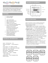
FAN AUTOHRS
CHECK BATTERY
F
AM
MON
FAN AUTO
HEATHEAT
HRS
CHECK BATTERY
F
AM
MON WED THU FRI SAT SUNTUEWED THU FRI SAT SUNTUE
18 18
19 20 21
22
25
2324
Figure 1. The Display
LARLAR
LARLAR
LAR
GE LIGHTED (LGE LIGHTED (L
GE LIGHTED (LGE LIGHTED (L
GE LIGHTED (L
CD) DISPLACD) DISPLA
CD) DISPLACD) DISPLA
CD) DISPLA
YY
YY
Y
The thermostat display alternately shows
the current time and the current tempera-
ture on the left side. The display also
shows the temperature you have pro-
grammed or set on the right side of your
screen.
18
Displays system mode (
HEAHEA
HEAHEA
HEA
TT
TT
T,
OFFOFF
OFFOFF
OFF,
COOLCOOL
COOLCOOL
COOL,
AA
AA
A
UTUT
UTUT
UT
OO
OO
O,
HOLDHOLD
HOLDHOLD
HOLD,
VV
VV
V
AA
AA
A
CA CA
CA CA
CA or
HUMDHUMD
HUMDHUMD
HUMD). During programming displays the
time period (
MOR,MOR,
MOR,MOR,
MOR,
D D
D D
D
AA
AA
A
YY
YY
Y
,,
,,
,
EVE, EVE,
EVE, EVE,
EVE,
NHT NHT
NHT NHT
NHT)
being programmed. In the configuration
menu, the menu item name is shown, one
word at a time (
PRPR
PRPR
PR
GMGM
GMGM
GM
MODEMODE
MODEMODE
MODE,
EMREMR
EMREMR
EMR,
COOLCOOL
COOLCOOL
COOL
FF
FF
F
AN AN
AN AN
AN
DELADELA
DELADELA
DELA
OFFOFF
OFFOFF
OFF, etc.).
19
CHECK BCHECK B
CHECK BCHECK B
CHECK B
AA
AA
A
TTERTTER
TTERTTER
TTER
YY
YY
Y appears when the
“AA” alkaline batteries are weak and
should be replaced.
BB
BB
B
AA
AA
A
TTERTTER
TTERTTER
TTER
YY
YY
Y appears
when the thermostat is running on battery
power only.
CHECK STCHECK ST
CHECK STCHECK ST
CHECK ST
AA
AA
A
T T
T T
T appears when
the thermostat detects certain problems
within itself.
CHECK SYCHECK SY
CHECK SYCHECK SY
CHECK SY
STEM STEM
STEM STEM
STEM appears
when the thermostat detects certain
problems in the heating or humidity
system.
20
Indicates the length of time remaining
in a temporary hold condition. Also
indicates the length of time remaining in
VACATION mode.
21
Displays
FF
FF
F
AN ONAN ON
AN ONAN ON
AN ON when the fan is
operating continuously. Displays
FF
FF
F
ANAN
ANAN
AN
AA
AA
A
UTUT
UTUT
UT
OO
OO
O when the fan cycles with the
heating or cooling system.
22
Displays the setpoint temperature. In
HUMD mode, shows humidity setpoint.
23
Alternately displays room temperature
and time of day. In HUMD mode, shows
actual humidity.
24
Shows the current day of the week.
When programming, shows the day(s)
being programmed.
25
The word
HEAHEA
HEAHEA
HEA
TT
TT
T or
COOLCOOL
COOLCOOL
COOL will appear
above or below the setpoint if area
18
is
needed to display other information.
Introduction

4
INSTALLATION AND CONFIGURATION
This White-Rodgers Automatic
Setback Digital Thermostat uses
microcomputer technology to provide
precise time, temperature and humidity
SPECIFICATIONSSPECIFICATIONS
SPECIFICATIONSSPECIFICATIONS
SPECIFICATIONS
Model 1F97-391 Model 1F97-391
Model 1F97-391 Model 1F97-391
Model 1F97-391 7 Day Programming
ELECTRICAL DELECTRICAL D
ELECTRICAL DELECTRICAL D
ELECTRICAL D
AA
AA
A
TT
TT
T
AA
AA
A
Electrical Rating:
17 to 30 VAC, 50/60 Hz
0.05 to 1.5 Amps
1.5 Amps Maximum Total Load
(All terminals combined)
THERMAL DTHERMAL D
THERMAL DTHERMAL D
THERMAL D
AA
AA
A
TT
TT
T
AA
AA
A
Setpoint Temperature Range:
45° to 99°F (7° to 37°C)
Setpoint Humidity Range:
10% to 45%
Operating Ambient Temperature:
32° to 110°F (0° to 43°C)
Operating Humidity Range:
90% non-condensing max.
Shipping Temperature Range:
-4° to 131°F (-20° to 55°C)
control. This thermostat offers the
flexibility to design heating and
cooling programs that fit personal
needs. This thermostat is adaptable to
most 24 Volt residential forced air,
hydronic (hot water or steam), electric
heat systems.
Standard Systems:
Fuel: Gas, Oil, Electric
Type: Heating/Cooling, Heat Only,
Hot Water or Steam Systems, Cool
Only

5
PRECAUTIONSPRECAUTIONS
PRECAUTIONSPRECAUTIONS
PRECAUTIONS
WARNING
!
Do not shorDo not shor
Do not shorDo not shor
Do not shor
t out tert out ter
t out tert out ter
t out ter
minals onminals on
minals onminals on
minals on
gg
gg
g
as vas v
as vas v
as v
alvalv
alvalv
alv
e or primare or primar
e or primare or primar
e or primar
y contry contr
y contry contr
y contr
ol tool to
ol tool to
ol to
test.test.
test.test.
test.
Shor Shor
Shor Shor
Shor
t or incort or incor
t or incort or incor
t or incor
rr
rr
r
ect wiringect wiring
ect wiringect wiring
ect wiring
will damawill dama
will damawill dama
will dama
gg
gg
g
e there ther
e there ther
e ther
mostamosta
mostamosta
mosta
t andt and
t andt and
t and
could cause percould cause per
could cause percould cause per
could cause per
sonal injursonal injur
sonal injursonal injur
sonal injur
y and/y and/
y and/y and/
y and/
or pror pr
or pror pr
or pr
operoper
operoper
oper
ty damaty dama
ty damaty dama
ty dama
gg
gg
g
ee
ee
e
..
..
.
Do not use on cirDo not use on cir
Do not use on cirDo not use on cir
Do not use on cir
cuits ecuits e
cuits ecuits e
cuits e
xx
xx
x
ceedingceeding
ceedingceeding
ceeding
specified vspecified v
specified vspecified v
specified v
oltaolta
oltaolta
olta
gg
gg
g
ee
ee
e
..
..
.
Higher Higher
Higher Higher
Higher
vv
vv
v
oltaolta
oltaolta
olta
gg
gg
g
e will damae will dama
e will damae will dama
e will dama
gg
gg
g
e contre contr
e contre contr
e contr
ol andol and
ol andol and
ol and
could cause shoccould cause shoc
could cause shoccould cause shoc
could cause shoc
k or firk or fir
k or firk or fir
k or fir
ee
ee
e
hazard.hazard.
hazard.hazard.
hazard.
TT
TT
T
herher
herher
her
mostamosta
mostamosta
mosta
t installat installa
t installat installa
t installa
tiontion
tiontion
tion
and all components of theand all components of the
and all components of theand all components of the
and all components of the
system shall confsystem shall conf
system shall confsystem shall conf
system shall conf
oror
oror
or
m to Class IIm to Class II
m to Class IIm to Class II
m to Class II
circir
circir
cir
cuits per the NEC codecuits per the NEC code
cuits per the NEC codecuits per the NEC code
cuits per the NEC code
..
..
.
TT
TT
T
o pro pr
o pro pr
o pr
ee
ee
e
vv
vv
v
ent electrical shocent electrical shoc
ent electrical shocent electrical shoc
ent electrical shoc
k and/k and/
k and/k and/
k and/
or equipment damaor equipment dama
or equipment damaor equipment dama
or equipment dama
gg
gg
g
ee
ee
e
,,
,,
,
discon- discon-
discon- discon-
discon-
nect electric ponect electric po
nect electric ponect electric po
nect electric po
ww
ww
w
er to system aer to system a
er to system aer to system a
er to system a
tt
tt
t
main fuse or cirmain fuse or cir
main fuse or cirmain fuse or cir
main fuse or cir
cuit brcuit br
cuit brcuit br
cuit br
eakeak
eakeak
eak
er boer bo
er boer bo
er bo
xx
xx
x
until installauntil installa
until installauntil installa
until installa
tion is completetion is complete
tion is completetion is complete
tion is complete
..
..
.
CAUTION
!
WARNING
!
Do not wire HM1 or HM2 fromDo not wire HM1 or HM2 from
Do not wire HM1 or HM2 fromDo not wire HM1 or HM2 from
Do not wire HM1 or HM2 from
therther
therther
ther
mostamosta
mostamosta
mosta
t (24 vt (24 v
t (24 vt (24 v
t (24 v
olts) to HUM onolts) to HUM on
olts) to HUM onolts) to HUM on
olts) to HUM on
ignition contrignition contr
ignition contrignition contr
ignition contr
ol (120 vol (120 v
ol (120 vol (120 v
ol (120 v
olts).olts).
olts).olts).
olts).
NOTE
This thermostat is intended for use
with a low voltage system. Do not use
directly on a line voltage system unless
an isolation relay/transformer is
installed.
Do not exceed the ratings shown in the
Specifications section, preceding page.
If in doubt about the electrical ratings
of your heating/cooling system, have it
inspected by a qualified heating and air
conditioning contractor or licensed
electrician.
All wiring must conform to local and
national electrical codes and ordi-
nances.
This control is a precision instrument,
and should be handled carefully.
Rough handling or distorting compo-
nents could cause the control to
malfunction.
RR
RR
R
ead all instread all instr
ead all instread all instr
ead all instr
uctions thoructions thor
uctions thoructions thor
uctions thor
oughloughl
oughloughl
oughl
yy
yy
y
befbef
befbef
bef
oror
oror
or
e bee be
e bee be
e be
ginning installaginning installa
ginning installaginning installa
ginning installa
tion.tion.
tion.tion.
tion.
Installation/Configuration

6
INSTINST
INSTINST
INST
ALLAALLA
ALLAALLA
ALLA
TION TION
TION TION
TION
AND CONFIGURAAND CONFIGURA
AND CONFIGURAAND CONFIGURA
AND CONFIGURA
TIONTION
TIONTION
TION
Shut off electricity at main fuse or
circuit breaker box until installation is
complete AND the jumper leads (fig.
10, page 17) on the back of the
thermostat are configured properly.
Remove the front cover of the old
thermostat. With wires still attached,
remove wall plate from the wall.
Identify each wire attached to the
thermostat using one of the labels
enclosed with the new thermostat.
Disconnect the wires from the old
thermostat one at a time. DO NOT let
the wires fall back into the wall.
Install the new thermostat using the
following procedures.
REMOVE OLD THERMOSTATREMOVE OLD THERMOSTAT
REMOVE OLD THERMOSTATREMOVE OLD THERMOSTAT
REMOVE OLD THERMOSTAT
Remove packing material from the
thermostat. Place fingers of one hand
on the center top and bottom portion
of the thermostat. Grasp the base in the
other hand on top and bottom center
and gently pull straight out. Forcing or
prying on the thermostat will cause
damage to the unit.
Place the base over the hole in the wall
where the wires come out and mark
mounting hole locations base as a
template. Drill
3
/16” pilot holes, and
install screw anchors in the wall.
Run wires through hole in base and
attach base to wall (see fig. 2, page 7).
Insert the wires into the terminals on
the base using the appropriate wiring
diagram and tighten the terminal
screws.
ATTACH BASE TO WALLATTACH BASE TO WALL
ATTACH BASE TO WALLATTACH BASE TO WALL
ATTACH BASE TO WALL
This product does not contain mercury.
However, this product may replace a
unit which contains mercury.
Do not open mercury cells. If a cell
becomes damaged, do not touch any
spilled mercury. Wearing non-
absorbent gloves, take up the spilled
mercury with sand or other absorbent
material and place into a container
which can be sealed. If a cell becomes
damaged, the unit should be discarded.
Mercury must not be discarded in
household trash. When the unit this
product is replacing is to be discarded,
place in a suitable container and return
to White-Rodgers at 2895 Harrison
Street, Batesville, AR 72501 for proper
disposal.
ATTENTION!ATTENTION!
ATTENTION!ATTENTION!
ATTENTION!

7
HM1
WRH
RC
G
Y
HM2
6
S1
S2
S3
1
2
3
4
1
Figure 2 – Thermostat base
1
Mounting screws
2
Pull wires through this opening
3
Insert wires into terminal holes, then tighten screws
4
Screw anchors
Before the power is turned on, the
thermostat must be configured to
operate properly with the system. See
CONFIGURATION on page 16 in this
manual.
CONFIGURINGCONFIGURING
CONFIGURINGCONFIGURING
CONFIGURING
AND PROGRAMMINGAND PROGRAMMING
AND PROGRAMMINGAND PROGRAMMING
AND PROGRAMMING
Installation/Configuration

8
HM1 W RH RC G Y HM2 6
W
RH
1
2
3
HM1 HM2
6
Y
G
W
RC RH
E
H
J
I
M
K
L
WIRING DIAWIRING DIA
WIRING DIAWIRING DIA
WIRING DIA
GRAMSGRAMS
GRAMSGRAMS
GRAMS
All wiring diagrams are for typical systems only. Refer to equipment manufacturers' instructions for specific system wiring
information.
NOTE: Ensure that RED RH/RC jumper wire (provided with
thermostat) is connected between thermostat's RH and RC
terminals for proper operation with this system.
1
From heating system
2
From 24 VAC transformer
3
Red jumper wire (provided)
For humidifier wiring see pages 14-15.
See page 9 for letter identification.
Figure 3 – Typical wiring diagram for heating only, single transformer system

9
A
Humidifier System
B
Zone Valve
C
Cooling System
D
Fan Relay
E
Heating System
H
Jumper Wire
I
TRANSFORMER
J
24 VAC Side
K
120 VAC Side
L
Hot Side
M
Neutral Side
N
HEATING TRANSFORMER
O
COOLING TRANSFORMER
P
Jumper Wire (field-installed)
LETTER IDENTIFICATION FOR WIRING DIAGRAMS
Installation/Configuration

10
HM1 W RH RC G Y HM2 6
G
Y
5
3
2
4
R
H
W
1
HM1 HM2
6
Y
G
W
RC RH
ED
C
H
J
I
M
K
L
1
From heating system
2
From 24 VAC transformer
3
Red jumper wire (provided)
4
From fan relay
5
From cool system
For humidifier wiring see pages 14-15.
See page 9 for letter identification.
NOTE: Ensure that RED RH/RC jumper wire (provided with
thermostat) is connected between thermostat's RH and RC
terminals for proper operation with this system.
NOTE: For three-wire heat only system, connect terminals
GG
GG
G
,,
,,
,
WW
WW
W
and
RHRH
RHRH
RH. For cool only system, connect terminals
YY
YY
Y
,,
,,
,
G G
G G
G and
RHRH
RHRH
RH.
Figure 4 – Typical wiring diagram for heat only, cool only, & heat/cool single transformer system

11
HM1 W RH RC G Y HM2 6
W
R
H
1
2
6
4
3
HM1 HM2
Y
G
W
RC
RH
H
J
I
M
K
L
6
6
1
4
5
2
B
1
From heating system
2
From 24 VAC transformer
(through zone valve)
3
Red jumper wire (provided)
4
From zone valve system
For humidifier wiring see pages 14-15.
See page 9 for letter identification.
NOTE: Thermostat must have batteries installed.
NOTE: Ensure that RED RH/RC jumper wire (provided with
thermostat) is connected between thermostat's RH and RC
terminals for proper operation with this system.
Figure 5 – Typical wiring diagram for heat only, three-wire, zone valve system
Installation/Configuration

12
HM1 W RH RC G Y HM2 6
W
R
H
1
2
RC
G
Y
5
3
4
HM1 HM2
6
Y
G
W
RC RH
ED
C
J
I
M
K
L
J
O
M
K
L
1
From heating system
2
From 24 VAC heating transformer
3
From 24 VAC cooling transformer
4
From fan relay
5
From cooling system
For humidifier wiring see pages 14-15.
See page 9 for letter identification.
Figure 6 – Typical wiring diagram for heat/cool, two-transformer system

13
Installation/Configuration
HM1 HM2
6
Y
G
W
RC
RH
D
C
J
I
M
K
L
HM1 W RH RC G Y HM2 6
1
R
C
G
Y
3
2
1
From 24 VAC cooling transformer
2
From fan relay
3
From cooling system
For humidifier wiring see pages 14-15.
See page 9 for letter identification.
Figure 7 – Typical wiring diagram for three-wire cooling system

14
HM1
6 Y G W
HM2
RC RH
HM1 W RH RC G Y HM2 6
A
1
L
M
KJ
1
I
H
M
NOTE: Two terminal choices (HM1 or HM2) are provided for
humidifier control. When the humidity setting is higher than the
room humidity:
HM1 turns off the humidifier when the call for heat ends.
HM2 powers the humidifier an additional 30 seconds after the
call for heat ends to provide slightly more humidity output.
Most installers will use HM1 unless they feel more humidity is
desirable.
Figure 8 – Typical wiring diagram for 24V humidifier system
1
From humidity system
See page 9 for letter identification.

15
HM1 6 Y G W
HM2
RC RH
HM1 W RH RC G Y HM2 6
A
1
L
M
K
K
J
1
I
Relay
90-290Q
or equivalent
HM
Figure 9 – Typical wiring diagram for 120V humidifier system
1
From humidity system
See page 9 for letter identification.
Installation/Configuration

16
Before turning power on to the system,
the jumpers on the back of the
thermostat must be configured to
operate correctly with the system
equipment.
This thermostat is configured from the
factory to operate a standard fossil fuel
(gas, oil, etc.), forced hot air system
with a single stage air conditioning
compressor and fan. This is the correct
configuration for any system that
DOES NOT require the thermostat to
energize the fan on a call for heat.
JUMPERSJUMPERS
JUMPERSJUMPERS
JUMPERS
A remote sensor can be used with this
thermostat. To use a remote sensor,
jumper W922 must be clipped (see fig.
10) and the REMT SEN option in the
configuration menu must be set to ON.
CONFIGURACONFIGURA
CONFIGURACONFIGURA
CONFIGURA
TIONTION
TIONTION
TION
If you have an electric heat or other
system that REQUIRES the thermostat
to control the fan, find and cut the
jumper lead labelled W914 (see fig.
10). This will allow the thermostat to
energize the fan instantly on a call for
heat. If you are unsure if the system
requires the thermostat to control the
fan, contact a qualified heating and air
conditioning service person.

17
1 32
W922
W914
1
Clip for remote sense
2
3-pin connector
3
Clip for electric heat
Figure 10 – Jumper locations
Installation/Configuration

18
Step Press Button(s) Displayed (Factory Default) Press or to select: COMMENTS
1 EMR
(ON)
OFF
2 SET CYCL HEAT
(05)
02 - 40
Adjusts heat anticipation value (2 through 40)
See page 20
3 SET CYCL COOL
(12)
09 - 40
4 COOL FAN DELA OFF
(01)
01 - 127
5 COOL FAN DELA ON
(04)
01 - 05
6 COMP LOCK
(OFF)
ON
7 SYSTEM
(HEAT-OFF-COOL-AUTO)
HEAT-OFF,
COOL-OFF,
HEAT-OFF-COOL
Selects system switch choices for heat only,
cool only, heat/cool or automatic changeover
See page 21
Selects EMR option ON or OFF
See page 32
Adjusts cool anticipation value (9 through 40)
See page 20
Adjusts cool fan-off delay (1 through 127 sec.)
See page 20
Selects compressor lockout ON or OFF (see NOTE)
See page 21
Adjusts cool fan-on delay (1 through 5 sec.)
See page 20
TIME
FWD
TIME
FWD
TIME
FWD
TIME
FWD
TIME
FWD
TIME
FWD
TIME
FWD
TIME
BACK
CONFIGURACONFIGURA
CONFIGURACONFIGURA
CONFIGURA
TION MENUTION MENU
TION MENUTION MENU
TION MENU
The configuration menu allows you to set thermostat operating characteristics to your system or personal requirements.
To enter the menu, press TIME
FWD
and TIME
BACK
once at the same time. Press TIME
FWD
to advance through the
menu options. Press
arrow keys to change options. Either the installer or the operator may change shaded
options. We recommend that other options be set by the installer.
/