Page is loading ...

Dell PowerEdge R930 System
Owner's Manual
Regulatory Model: E37S Series
Regulatory Type: E37S001

Notes, cautions, and warnings
NOTE: A NOTE indicates important information that helps you make better use of your computer.
CAUTION: A CAUTION indicates either potential damage to hardware or loss of data and tells you
how to avoid the problem.
WARNING: A WARNING indicates a potential for property damage, personal injury, or death.
Copyright © 2015 Dell Inc. All rights reserved. This product is protected by U.S. and international copyright and
intellectual property laws. Dell
™
and the Dell logo are trademarks of Dell Inc. in the United States and/or other
jurisdictions. All other marks and names mentioned herein may be trademarks of their respective companies.
2015 – 06
Rev. A00

Contents
1 About the PowerEdge R930................................................................................9
Front panel features and indicators......................................................................................................9
LCD panel features...............................................................................................................................11
Home screen..................................................................................................................................12
Setup menu....................................................................................................................................12
View menu..................................................................................................................................... 13
Diagnostic indicators...........................................................................................................................13
Hard drive indicator codes..................................................................................................................15
SSD LED indicator pattern...................................................................................................................16
Back panel features and indicators..................................................................................................... 17
NIC indicator codes.............................................................................................................................19
Power supply unit indicator codes..................................................................................................... 19
Documentation matrix........................................................................................................................ 21
Quick Resource Locator (QRL)...........................................................................................................22
2 Performing initial system configuration ....................................................... 23
Setting up your system....................................................................................................................... 23
Setting up and configuring the iDRAC IP address ............................................................................ 23
Logging in to iDRAC............................................................................................................................24
Methods of installing the operating system.......................................................................................24
Managing your system remotely........................................................................................................24
Downloading drivers and firmware.................................................................................................... 25
3 Pre-operating system management applications........................................26
Navigation keys................................................................................................................................... 26
About System Setup............................................................................................................................ 27
Entering system setup................................................................................................................... 27
System Setup Main Menu..............................................................................................................27
System BIOS screen...................................................................................................................... 27
System Information screen...........................................................................................................28
Memory Settings screen............................................................................................................... 29
Processor Settings screen.............................................................................................................30
SATA Settings screen..................................................................................................................... 31
Boot Settings screen..................................................................................................................... 32
Network Settings screen............................................................................................................... 33
Integrated Devices screen............................................................................................................ 33
Serial Communication screen...................................................................................................... 34
System Profile Settings screen......................................................................................................35
3

System Security Settings screen................................................................................................... 37
Miscellaneous Settings screen......................................................................................................38
About Boot Manager...........................................................................................................................39
Entering Boot Manager ................................................................................................................ 39
Boot Manager main menu............................................................................................................ 39
About Dell Lifecycle Controller..........................................................................................................40
Changing the boot order....................................................................................................................40
Choosing the system boot mode...................................................................................................... 40
Assigning a system or setup password...............................................................................................41
Using your system password to secure your system.........................................................................41
Deleting or changing an existing system password or setup password...........................................42
Operating with a setup password enabled........................................................................................ 42
Embedded system management....................................................................................................... 43
iDRAC Settings utility.......................................................................................................................... 43
Entering the iDRAC Settings utility............................................................................................... 43
Changing the Thermal Settings.................................................................................................... 43
4 Installing and removing system components...............................................45
Customer and field replaceable units................................................................................................ 45
Safety instructions...............................................................................................................................46
Before working inside your system....................................................................................................46
After working inside your system....................................................................................................... 46
Recommended tools.......................................................................................................................... 47
Front bezel (optional)..........................................................................................................................47
Installing the optional front bezel.................................................................................................47
Removing the optional front bezel...............................................................................................47
System cover.......................................................................................................................................48
Removing the system cover......................................................................................................... 48
Installing the system cover........................................................................................................... 49
Inside the system................................................................................................................................ 50
Chassis intrusion switch...................................................................................................................... 51
Removing the chassis intrusion switch.........................................................................................51
Installing the chassis intrusion switch.......................................................................................... 52
Cable management tray..................................................................................................................... 53
Removing the cable management tray ....................................................................................... 53
Installing the cable management tray.......................................................................................... 55
System memory.................................................................................................................................. 56
General memory module installation guidelines.........................................................................59
Mode-specific guidelines..............................................................................................................59
Advanced ECC (Lockstep)............................................................................................................ 60
Memory optimized (independent channel) mode.......................................................................60
Memory sparing............................................................................................................................ 60
4

Memory mirroring.........................................................................................................................60
Fault Resilient Memory.................................................................................................................. 61
Sample memory configurations....................................................................................................61
Memory riser....................................................................................................................................... 62
Removing a memory riser blank...................................................................................................62
Installing a memory riser blank.....................................................................................................63
Removing a memory riser.............................................................................................................64
Installing a memory riser...............................................................................................................65
Removing memory modules from the memory riser..................................................................66
Installing memory modules into the memory riser..................................................................... 68
Memory riser and fan cage.................................................................................................................70
Removing the memory riser and fan cage...................................................................................70
Installing the memory riser and fan cage..................................................................................... 71
Hard drives...........................................................................................................................................72
Removing a 2.5 inch hard drive blank...........................................................................................73
Installing a 2.5 inch hard drive blank............................................................................................ 74
Removing a hot-swappable hard drive carrier.............................................................................75
Installing a hot-swappable hard drive carrier...............................................................................76
Removing a hard drive from a hard drive carrier..........................................................................77
Installing a hard drive into a hard drive carrier............................................................................. 77
Optical drive (optional)........................................................................................................................78
Removing the optical drive........................................................................................................... 78
Installing the optical drive............................................................................................................. 79
Cooling fans........................................................................................................................................80
Removing a cooling fan................................................................................................................80
Installing a cooling fan.................................................................................................................. 81
Removing the fan tray...................................................................................................................82
Installing the fan tray ....................................................................................................................83
Internal USB memory key (optional).................................................................................................. 84
Replacing the internal USB key.....................................................................................................84
Expansion cards and expansion card risers....................................................................................... 85
Expansion card installation guidelines......................................................................................... 85
Removing the left expansion card riser blank..............................................................................88
Installing the left expansion card riser blank................................................................................89
Removing the right expansion card riser blank........................................................................... 90
Installing the right expansion card riser blank............................................................................. 90
Removing the left expansion card riser....................................................................................... 90
Installing the left expansion card riser..........................................................................................92
Removing the right expansion card riser..................................................................................... 92
Installing the right expansion card riser....................................................................................... 93
Removing an expansion card from expansion card risers...........................................................93
Installing an expansion card into the expansion card risers........................................................97
5

NDC riser............................................................................................................................................. 97
Removing the NDC riser...............................................................................................................98
Installing the NDC riser.................................................................................................................99
Network daughter card.......................................................................................................................99
Removing the network daughter card.......................................................................................100
Installing the network daughter card..........................................................................................101
SD vFlash media card........................................................................................................................ 101
Replacing an SD vFlash media card............................................................................................102
Internal dual SD module................................................................................................................... 102
Removing an internal SD card.................................................................................................... 103
Installing an internal SD card...................................................................................................... 103
Removing the internal dual SD module..................................................................................... 104
Installing the internal dual SD module....................................................................................... 106
Integrated storage controller card...................................................................................................106
Removing the integrated storage controller card..................................................................... 107
Installing the integrated storage controller card....................................................................... 108
Processors and heat sinks................................................................................................................ 109
Removing a heat sink..................................................................................................................109
Removing a processor.................................................................................................................110
Installing a processor...................................................................................................................113
Installing a heat sink.....................................................................................................................115
Removing a processor blank and heat sink blank ..................................................................... 117
Installing a processor blank and heat sink blank........................................................................118
Power supply units............................................................................................................................ 119
Hot spare feature.........................................................................................................................120
Removing an AC power supply unit...........................................................................................120
Installing an AC power supply unit..............................................................................................121
Removing the power supply unit blank......................................................................................122
Installing the power supply unit blank........................................................................................123
Power distribution board.................................................................................................................. 124
Removing the power supply unit bay.........................................................................................124
Installing the power supply unit bay...........................................................................................125
Removing the power distribution board.................................................................................... 126
Installing the power distribution board.......................................................................................127
System battery...................................................................................................................................128
Replacing the system battery......................................................................................................128
Hard drive backplane........................................................................................................................ 129
Removing the hard drive backplane...........................................................................................130
Installing the hard drive backplane.............................................................................................138
SAS expander daughter card............................................................................................................ 139
Removing the SAS expander daughter card.............................................................................. 139
Installing the SAS expander daughter card................................................................................ 140
6

Control panel assembly.....................................................................................................................141
Removing the control panel board.............................................................................................141
Installing the control panel board.............................................................................................. 142
System board.....................................................................................................................................143
Removing the system board.......................................................................................................143
Installing the system board.........................................................................................................145
Trusted Platform Module..................................................................................................................148
Re-enabling the TPM for BitLocker users.................................................................................. 148
Re-enabling the TPM for TXT users........................................................................................... 148
5 Troubleshooting your system........................................................................149
Safety first—for you and your system...............................................................................................149
Troubleshooting system startup failure........................................................................................... 149
Troubleshooting external connections............................................................................................149
Troubleshooting the video subsystem.............................................................................................149
Troubleshooting a USB device......................................................................................................... 150
Troubleshooting a serial I/O device................................................................................................. 150
Troubleshooting a NIC...................................................................................................................... 151
Troubleshooting a wet system..........................................................................................................151
Troubleshooting a damaged system................................................................................................152
Troubleshooting the system battery................................................................................................ 153
Troubleshooting power supply units................................................................................................153
Troubleshooting cooling problems..................................................................................................154
Troubleshooting cooling fans...........................................................................................................155
Troubleshooting system memory.................................................................................................... 155
Troubleshooting an internal USB key...............................................................................................156
Troubleshooting an SD card............................................................................................................. 157
Troubleshooting an optical drive..................................................................................................... 158
Troubleshooting a hard drive........................................................................................................... 158
Troubleshooting a storage controller.............................................................................................. 159
Troubleshooting expansion cards....................................................................................................160
Troubleshooting processors............................................................................................................ 160
6 Using system diagnostics................................................................................162
Dell embedded system diagnostics..................................................................................................162
When to use the embedded system diagnostics.......................................................................162
Running the Embedded System Diagnostics from Boot Manager............................................162
Running the Embedded System Diagnostics from the Dell Lifecycle Controller.....................163
System diagnostic controls.........................................................................................................163
7 Jumpers and connectors................................................................................ 164
System board jumper settings..........................................................................................................164
7

System board connectors.................................................................................................................165
Disabling a forgotten password........................................................................................................168
8 Technical specifications..................................................................................169
9 Getting help.......................................................................................................176
Contacting Dell..................................................................................................................................176
Locating your system Service Tag....................................................................................................176
Quick Resource Locator (QRL).........................................................................................................176
8

1
About the PowerEdge R930
The Dell PowerEdge R930 is a rack server that supports up to four processors based on the Intel
E7-8800/4800 v3 product family, eight memory risers with a capacity of 12 DIMMs per riser, and up to 24
hard drives/SSDs.
The R930 systems are available in the following configurations:
System Configuration
Four hard drive
systems
Up to four 2.5 inch, hot-swappable hard drives/SSDs with redundant PSU
Twenty four hard
drive systems
Up to twenty four 2.5 inch, hot-swappable hard drives/SSDs with redundant PSU
Sixteen hard
drive/SSD plus eight
PCIe SSD systems
Up to sixteen 2.5 inch, hot-swappable hard drives/SSDs plus eight PCIe SSDs with
redundant PSU
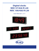
Front panel features and indicators
Figure 1. Front panel features and indicators
9

Item Indicator, Button, or
Connector
Icon Description
1
vFlash media card slot
Enables you to insert a vFlash media card.
2 Power-on indicator,
power button
The power-on indicator lights when the system
power is on. The power button controls the power
supply output to the system.
NOTE: On ACPI-compliant operating systems,
turning off the system using the power button
causes the system to perform a graceful
shutdown before power to the system is
turned off.
3 NMI button
Used to troubleshoot software and device driver
errors when running certain operating systems.
This button can be pressed using the end of a
paper clip.
Use this button only if directed to do so by
qualified support personnel or by the operating
system documentation.
4 System identification
button
The identification buttons on the front and back
panels can be used to locate a particular system
within a rack. When one of these buttons is
pressed, the LCD panel on the front and the
system status indicator on the back flashes until
one of the buttons is pressed again.
Press the system identification button to turn the
system ID on or off.
If the system stops responding during POST, press
and hold the system ID button for more than five
seconds to enter BIOS progress mode.
To reset iDRAC (if not disabled in F2 iDRAC setup),
press and hold the button for more than 15
seconds.
5 Video connector Enables you to connect a VGA display to the
system.
6 LCD menu buttons Enables you to navigate the control panel LCD
menu.
7 USB connectors (2) Enables you to connect USB devices to the system.
The ports are USB 2.0-compliant.
8 Enterprise Service Tag A slide-out label panel, which allows you to record
system information such as Service Tag, NIC, MAC
address, and so on, as per your need.
9 Hard drives (number of
drives will be either 4 or
2.5 inch hard drives
10

Item Indicator, Button, or
Connector
Icon Description
24 depending on the
backplane
configurations)
NOTE: On the backplane supported Flash
devices, there are 3 bays in total. The first two
bays are for PCIe Flash devices with two sets
of drives labelled 0 through 3. The bay 3 is for
SAS drives labelled 0 through 15.
10 Rack ears Enables you to pull the system out of the rack.
11 Slide lock A lock that pops out the ejector handle for the
optical drive.
12 Optical drive (optional) One optional SATA DVD-ROM drive or DVD+/- RW
drive.
LCD panel features
The system's LCD panel provides system information and status and error messages to indicate when the
system is operating correctly or when the system needs attention.
• The LCD backlight lights blue during normal operating conditions and lights amber to indicate an
error condition.
• The LCD backlight is turned off when the system is in standby mode and can be turned on by pressing
either the Select, Left, or Right button on the LCD panel.
• The LCD backlight remains OFF if LCD messaging is turned off through the iDRAC utility, the LCD
panel, or other tools.
Figure 2. LCD panel Features
Item Button Description
1 Left Moves the cursor back in one-
step increments.
2 Select Selects the menu item
highlighted by the cursor.
3 Right Moves the cursor forward in one-
step increments.
During message scrolling:
11

Item Button Description
• Press once to increase
scrolling speed
• Press again to stop
• Press again to return to the
default scrolling speed
• Press again to repeat the
cycle
Home screen
The Home screen displays user-configurable information about the system. This screen is displayed
during normal system operation when there are no status messages or errors. When the system is in
standby mode, the LCD backlight turns off after five minutes of inactivity if there are no error messages.
Press one of the three navigation buttons (Select, Left, or Right) to view the Home screen.
To navigate to the Home screen from another menu, follow the steps below.
1. Press and hold the up arrow until the Home icon is displayed.
2. Select the Home icon.
3. From the Home screen, press the Select button to enter the main menu.
Setup menu
NOTE: When you select an option in the Setup menu, you must confirm the option before
proceeding to the next action.
Option Description
iDRAC Select DHCP or Static IP to configure the network mode. If Static IP is selected,
the available fields are IP, Subnet (Sub), and Gateway (Gtw). Select Setup DNS to
enable DNS and to view domain addresses. Two separate DNS entries are available.
Set error Select SEL to display LCD error messages in a format that matches the IPMI
description in the SEL. This is useful when trying to match an LCD message with an
SEL entry.
Select Simple to display LCD error messages in a simplified user-friendly
description. For more information on error messages, see the Dell Event and Error
Messages Reference Guide at dell.com/esmmanuals.
Set home Select the default information to be displayed on the LCD Home screen. See View
menu to see the options and option items that can be set as the default on the
Home screen.
12

View menu
NOTE: When you select an option in the View menu, you must confirm the option before
proceeding to the next action.
Option Description
iDRAC IP Displays the IPv4 or IPv6 addresses for iDRAC8. Addresses include DNS (Primary
and Secondary), Gateway, IP, and Subnet (IPv6 does not have Subnet).
MAC Displays the MAC addresses for iDRAC, iSCSI, or Network devices.
Name Displays the name of the Host, Model, or User String for the system.
Number Displays the Asset tag or the Service tag for the system.
Power Displays the power output of the system in BTU/hr or Watts. The display format can
be configured in the Set home submenu of the Setup menu.
Temperature Displays the temperature of the system in Celsius or Fahrenheit. The display format
can be configured in the Set home submenu of the Setup menu.
Diagnostic indicators
The diagnostic indicators on the system front panel display error status during system startup.
NOTE: No diagnostic indicators are lit when the system is switched off. To start the system, plug it
into a working power source and press the power button.
Icon Description Condition Corrective action
Health
indicator
If the system is on, and in
good health, the indicator
lights solid blue.
None required.
The indicator blinks amber if
the system is on or in
standby, and if any error
exists (for example, a failed
fan or hard drive).
See the System Event Log or system
messages for the specific issue. For more
information on error messages, see the Dell
Event and Error Messages Reference Guide
at Dell.com/esmmanuals.
Invalid memory configurations can cause
the system to halt at startup without any
video output. See Getting help.
Hard drive
indicator
The indicator blinks amber if
a hard drive experiences an
error.
See the System Event Log to determine the
hard drive that has an error. Run the
appropriate Online Diagnostics test. Restart
system and run embedded diagnostics
(ePSA). If the hard drives are configured in a
RAID array, restart the system and enter the
host adapter configuration utility program.
13

Icon Description Condition Corrective action
Electrical
indicator
The indicator blinks amber if
the system experiences an
electrical error (for example,
voltage out of range, or a
failed power supply unit or
voltage regulator).
See the System Event Log or system
messages for the specific issue. If it is due to
a problem with the power supply, check the
LED on the power supply. Re-seat the
power supply by removing and reinstalling
it. If the problem persists, see Getting help.
Temperature
indicator
The indicator blinks amber if
the system experiences a
thermal error (for example, a
temperature out of range or
fan failure).
Ensure that none of the following
conditions exist:
• A cooling fan is removed or has failed.
• System cover, cooling shroud, EMI filler
panel, memory module blank, or back
filler bracket is removed.
• Ambient temperature is too high.
• External airflow is obstructed.
See Getting help.
Memory
indicator
The indicator blinks amber if
a memory error occurs.
See System Event Log or system messages
for the location of the failed memory.
Reinstall the memory device. If the problem
persists, see Getting help.
PCIe
indicator
The indicator blinks amber if
a PCIe card experiences an
error.
Restart the system. Update any required
drivers for the PCIe card. Re-install the card.
If the problem persists, see Getting help.
14

Hard drive indicator codes
Figure 3. Hard drive indicators
1. hard drive activity indicator 2. hard drive status indicator
3. hard drive
NOTE: If the hard drive is in Advanced Host Controller Interface (AHCI) mode, the status indicator
(on the right side) does not function and remains off.
Drive-status indicator pattern (RAID only) Condition
Blinks green two times per second Identifying drive or preparing for removal.
Off Drive ready for insertion or removal.
NOTE: The drive status indicator remains off until
all hard drives are initialized after the system is
turned on. Drives are not ready for insertion or
removal during this time.
Blinks green, amber, and turns off Predicted drive failure
Blinks amber four times per second Drive failed
Blinks green slowly Drive rebuilding
Steady green Drive online
Blinks green three seconds, amber three
seconds, and turns off six seconds
Rebuild aborted
15

SSD LED indicator pattern
Figure 4. SSD LED indicator pattern
1. SSD activity indicator 2. SSD status indicator
3. SSD
While the operating system is running, the status indicator provides the current status of the device. The
following table lists the device states along with the associated LED indicator codes.
Table 1. SSD LED indicator pattern
State Name Slot/Device State Status LED (Green) Status LED (Amber)
Device status off The server or device is
not powered up.
Off Off
Device online The device is powered
up.
On Off
Device identify (blink) The device is identifying
the slot location or is
indicating that the
device has received a
Prepare for Removal
command from the host
operating system.
On for 250 msec
Off for 250 msec
Off
Device failed The host operating
system no longer has
access to the device
because the device is
not responding or has
Off
On for 250 msec
Off for 250 msec
16

State Name Slot/Device State Status LED (Green) Status LED (Amber)
encountered a critical
error condition.
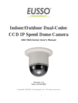
Back panel features and indicators
Figure 5. Back panel features and indicators
Item Indicator, Button, or
Connector
Icon Description
1 Power supply unit (PSU
3 and 4)
AC 750 W or 1100 W
2 PCIe expansion card
slots (8 or 10 depending
on the I/O risers
installed)
Enables you to connect PCI Express expansion
cards.
3 Power supply unit (PSU 1
and 2)
AC 750 W or 1100 W
4 Video connector Enables you to connect a VGA display to the
system.
5 iDRAC Enterprise port Dedicated management port.
NOTE: The port is available for use only if the
iDRAC8 Enterprise license is installed on your
system.
6 Ethernet connectors (4) Four integrated 10/100/1000 Mbps NIC
connectors
17

Item Indicator, Button, or
Connector
Icon Description
or
Four integrated connectors that include:
• Two 10/100/1000 Mbps NIC connectors
• Two 100 Mbps/1 Gbps/10 Gbps SFP+/10 GbE T
connectors
7 USB connectors (2) Enables you to connect USB devices to the system.
The ports are USB 2.0-compliant.
8 Serial connector Enables you to connect a serial device to the
system.
9 System identification
connector
Connects the optional system status indicator
assembly through the optional cable management
arm.
10 System identification
button
The identification buttons on the front and back
panels can be used to locate a particular system
within a rack.
Press the system identification button to turn the
system ID on or off.
If the system stops responding during POST, press
and hold the system ID button for more than five
seconds to enter BIOS progress mode.
To reset iDRAC (if not disabled in F2 iDRAC setup)
press and hold the button for more than 15
seconds.
18

NIC indicator codes
Figure 6. NIC indicators
1. link indicator 2. activity indicator
Convention Indicator pattern Description
A Link and activity indicators
are OFF
The NIC is not connected to the network.
B Link indicator is green The NIC is connected to a valid network at its maximum
port speed (1 Gbps).
C Link indicator is yellow The NIC is connected to a valid network at less than its
maximum port speed.
D Activity indicator is blinking
green
Network data is being sent or received.
Power supply unit indicator codes
Each AC power supply unit (PSU) has an illuminated translucent handle that serves as an indicator to
show whether power is present or a power fault has occurred.
19

Figure 7. AC PSU status indicator
1. AC PSU status indicator/handle
Convention Power indicator
pattern
Condition
A Green A valid power source is connected to the PSU and the PSU is
operational.
B Flashing green When the firmware of the PSU is being updated, the PSU handle
flashes green.
CAUTION: Do not disconnect the power cord or unplug the
PSU when updating firmware. If firmware update is
interrupted, the PSUs will not function. You must roll back the
PSU firmware by using Life cycle controller. See Dell Lifecycle
Controller User’s Guide at Dell.com/esmmanuals.
C Flashing green
and turns off
When hot-adding a PSU, the PSU handle flashes green five times at
4 Hz rate and turns off. This indicates that there is a PSU mismatch
with respect to efficiency, feature set, health status, and supported
voltage. Replace the PSU with a PSU that matches the capacity of
the other PSU.
CAUTION: For AC PSUs, use only PSUs with the Extended
Power Performance (EPP) label on the back. Mixing PSUs from
previous generations of Dell PowerEdge servers can result in a
PSU mismatch condition or failure to power on.
D Flashing amber Indicates a problem with the PSU.
20
/