Craftsman Air Compressor Owner's manual

Category
Air compressors
Type
Owner's manual

This manual is also suitable for

_ARS
CRAFTSMAN
NOTE: For identification of Re-
)air Parts, see separate Parts
List Manual.
IMPORTANT:
Read the Safety Guidelines
and All Instructions
Carefully Before Operating
GENERAL MANUAL FOR
PERMANENTLY LUBRICATED
TANK MOUNTED
TWIN CYLINDER
AIR COMPRESSOR
SAFETY GUIDELINES
ASSEMBLY
OPERATION
MAINTENANCE
TROUBLESHOOTING
REPAIR PARTS
Record in the spaces provided,
(1) The mode_ number which can be
found on the maintenance label on
the top of the motor cover or on the
tank,
(2) The code number which can be
found on the foil label on the rear of
the air tank.
(3) The Manufacturers Number is lo-
cated on the metal data plate which
is welded onto the backside of the
air tank. (This data plate is painted
the same color as the tank.)
Retain these numbers for future
reference.
Model No.
Code No.
Mfg. No.
I MG-PERMTWIN 6/18/93 I
Sears, Roebuck and Co., Chicago, IL 60684 U.S.A.
TABLE OF CONTENTS
Page
WARRANTY ............................................................................................................................... 2
SAFETY GUIDELINES ............................................................................................................... 3
WARNING CHART ..................................................................................................................... 3
GLOSSARY ............................................................................................................................... 5
ACCESSORIES FOR USE WITH SEARS AIR COMPRESSORS ............................................... 5
GENERAL INFORMATION ........................................................................................................ 5
DESCRIPTION OF OPERATION ............................................................................................... 6
ASSEMBLY ................................................................................................................................ 7
REMOVAL OF SHIPPING BOARDS AND INSTALLATION ........................................................ 7
INSTALLATION AND BREAK-IN PROCEDURES ...................................................................... 7
Location of Air Compressor .................................................................................................. 7
Lubrication and Oil ................................................................................................................ 7
Extension Cords ................................................................................................................... 8
Voltage and Circuit Protection .............................................................................................. 8
Grounding Instructions ......................................................................................................... 8
OPERATING PROCEDURES .................................................................................................... 9
MAINTENANCE ....................................................................................................................... 10
Air Filter- Inspection and Replacement .............................................................................. 10
Check Valve -Replacement ................................................................................................ 10
Safety Valve - Inspection .................................................................................................... 10
Motor .................................................................................................................................. 11
Storage .............................................................................................................................. 11
TROUBLESHOOTING GUIDE ................................................................................................. 12
HOW TO ORDER REPAIR PARTS ..........................................................................................16
FULL ONE YEAR WARRANTY ON AIR COMPRESSORS
Ifthis air compressor fails due to a defect in material orworkmanship within one year from the date of purchase, RETURN
IT TO THE NEAREST SEARS SERVICE CENTER/DEPARTMENT THROUGHOUT THE UNITED STATES AND SEARS
WILL REPAIR IT, FREE OF CHARGE,
Ifthisair compressoris usedfor commercialorrental purposes,thewarrantywillapplyfor ninetydaysfrom thedateof
purchase.
Thiswarrantygivesyouspecificlegal rightsand you may have otherrightswhichvary from stateto state.
Sears, Roebuck and Co., Sears Tower, Dept. 731CR-W, Chicago, IL 60684
SAFETY GUIDELINES
This manual contains information that is important for you to know and understand. This information relates to
protecting YOUR SAFETY and PREVENTING EQUIPMENT PROBLEMS. To help you recognize this information,
we use the following symbols. Please read the manual and pay attention to these sections.
URGENT SAFETY INFORMATION - A
HAZARD THAT WILL CAUSE
SERIOUS INJURY OR LOSS OF LIFE.
IMPORTANT SAFETY INFORMATION -
A HAZARD THAT MIGHTCAUSE
SERIOUS INJURY OR LOSS OF LIFE.
Information for preventing damage to
equipment.
NOTE
information that you should pay special
attention to.
HAZARDS CAN OCCUR IF EQUIPMENT IS NOT USED PROPERLY.
PLEASE READ THE FOLLOWING CHART.
WHAT TO
LOOK FOR
Hot Parts
Flammable
Vapors
Air Tank
WHAT COULD HAPPEN
The metalcompressorcomponents,such as mani-
fold, tubes, etc., become hotwhenthe air compressor
isrunning. If you touch them, you may be seriously
burned.
It isnormal forthe motorandpressure switchtospark
when compressorstartsor stops.A spark can ignite
vapors from gasolineor solvents,causing a fire or
explosion.
Modifications to air compressor components in an
attempt to reach higher air pressure can cause the air
tank to rupture or explode.
Incompatability between tank and compressor will
cause the tank to rupture.
Modifications to the airtankwill causeittc weaken.
HOW TO PREVENT IT
Avoid contact with metal components of the compres-
sor during or immediately after operation, Reaching
under or removing portions of the plastic enclosures
such as the filter cover and console cover exposes hot
surfaces. Attowcompressor to cool prior to servicing.
If spraying a flammable material, provide ample ven-
tilation. Never spray in a closed area. There must be
a flow of fresh air at all times.
Always operate the air compressor in well-ventilated
areas, freeofgasolineorothersolventvapors. Do not
operate the compressor near the spray area.
Do not adjust, remove or tamper with the safety valve
or pressure switch. If safety valve or pressure switch
replacement is necessary, a part with the same ratings
must be used.
Never replace the air tank with a different model or a
larger tank. Return to Authorized Service Center if
replacement is required.
Never drill into weld or in any way modify the air tank.
Thetankmay rupture or explode. Ifleaks deve op due
to corrosion or tank is damaged, return to Authorized
Service Center for replacement.
3
SAFETY GUIDELINES
WHAT TO
LOOK FOR
Compressed
Air
Electricity
Toxic Vapors
Unsuitable
Solvents
WHAT COULD HAPPEN
Compressed aircan propel dust, dirtor loose particles
it comes in contact with. These propelled particles
may cause serious injury or damage.
Too much air pressure appliedto air toolsor acces-
soriescan causedamage or riskofbursting.
Your air compressor is powered by electricity. Like
any other electrically powered device, if it is not used
properly it may cause electrical shock.
It is normal for compressedair to contain toxic or
irritatingvapors. Suchvaporsareharmfulifinhaled.
Certain materialsyou are spraying(like paint,weed
killer, sandor insecticide)canbe harmfulifyouinhale
them.
The solvents1,1,1 - Trichloroethaneand Methylene
Chloddecanchemicallyreectwith aluminumusedin
)aint spray guns, paint pumps, etc., and cause an
explosion.Thesesolventscan alsoreactwithgalva-
nizedcomponentsand causecorrosionand weaken-
ingofparts.Thisdoesnotaffectyourair compressor
- butit may affectthe equipmentbeing used.
HOW TO PREVENT IT
Neverpointany nozzleor sprayertowarda personor
any partof the body.
Alwayswear safetygogglesorglasseswhenusingthe
air compressor.
Always turntheair compressoroffb_ore attachingor
removing accessories.
Check the manufacturer's pressure rating for air
tools and accessories. Regulator outl_ pressure
must never exceed the maximum pressure rating.
NOTE: IF A REGULATOR IS NOT SUPPLIED
WITH YOUR COMPRESSOR, YOU MUST
INSTALL ONE BEFORE USING AIR TOOLS AND
ACCESSORIES WITH PRESSURE RATINGS
LESS THAN 200 PSIG,
Always unplug the air compressorprior to mainte-
nance or repair.
Never use the air compressoroutdoorswhen it is
raining.
Always plug the cord into an electrical outlet with the
specified voltage and adequate fuse protection.
Never directlyinhalethe compressedair producedby
this unit.
Readlabelsand safetydataforallmaterialsyouspray.
Followall safety precautions.
Use a mask or respirator ifthera isa chance of inhaling
toxic sprayed materials. Masks and respirators have
limits and will only provide protection against some
kinds and limited amounts of toxic material, Read
mask and respirator instructions carefully. Consult
with a safety expert orindustrial hygienist ifyou are not
sure about the use of a certain mask or respirator.
Ifthe material you intend tospray contains the solvents
listed at left (read the label or data sheet), do not use
accessories that contain aluminum or galvanized parts.
You must either change the material you intend to
spray, or use only stainless steel spray equipment.
4
GLOSSARY
CFM: Cubic feet per minute.
SCFM: Standard cubicfeet per minute; a unitofmeasure
of air delivery.
PSIG: Pounds per square inchgauge; a unit ofmeasure
of pressure.
ASME: American Society of Mechanical Engineers;
made, tested, inspected and registered to meet the
standards of the ASME.
U.L. Listed: This product is Listed by UndenNriters
Laboratories, Inc. (UL). Samples of this product have
been evaluated by UL and meet the applicable UL Stan-
dards for Safety.
Cut-In Pressure: While the motor isoff, air tank pressure
drops as you continue to use your accessory. When the
tank pressure drops to a certain low level the motor will
restart automatically. The low pressure at which the
motorautomatically re-starts iscalled =cut-in pressure."
Cut-Out Pressure: When you turn on your air compres-
sorand itbegins to run, air pressure inthe airtank begins
to build. It builds to a certain high pressure before the
motor automatically shuts off - protecting your air tank
from pressure higherthan itscapacity. The high pressure
at which the motor shuts off is called =cut-out pressure."
ACCESSORIES FOR USE WITH
SEARS AIR COMPRESSORS
The following acoessodes are available through the current general sale catalog or at full-line Sears stores.
.SPRAYGUNS
.BLOWGUNS
AIR CAULKING GUNS
.POWERWASHER
.SANDBLASTERS
*AIR BRUSHES
AIR LINE FILTERS
TIRE AIR CHUCKS
PAINT TANKS
-AIRTANKS
.INFLATORKITS
•QUICK CONNECTOR SETS
(various sizes)
.VISCOSIMETER
AIR PRESSURE REGULATORS
•OIL FOG LUBRICATORS
-AIRTOOLS:
Sanders
DdUs
Impact Wrenches
Hammers
AIR HOSE:
114", 5/16" or 3t8" I.D.
in vadous lengths
.NAILER/STAPLERS
Decking
Farming
Roofing
Siding
Finishing
Carpenting
Upholstery
Picture Framing
DRAIN CLEANER
.DUSTERGUN
GENERAL INFORMATION
You have purchased an air compressor unitconsisting of
a 2 cylinder, single-stage air compressor pump and air
tank. Included with portable compressors only are an air
hose, tire air chuck, wheels, regulator, gauges, and
handle. Stationary unitsare notsupplied with regulators.
This air compressor requires no oil. Now you can enjoy
all the benefits of having an air compressor without ever
having to purchase, add or change oil.
Youraircompressor can be used foroperating paint spray
guns, air tools, caulking guns, grease guns, air brushes,
sandblaster, or inflating tires and plastic toys, spraying
weed killers, insecticides, etc. An air pressure regulatoris
required for most of the applications.
An air filter which removes moisture and dirt from the
compressed air should be used where applicable.
These accessories can be purchased from most Sears
stores.
5
DESCRIPTION OF OPERATION
Air Compressor Pump: To compress air, the pistons
move up and down in the cylinders. On the downstroke,
air isdrawn inthrough the air intake valves. The exhaust
valves remain dosed. On the upstroke of the piston, air
iscompressed. The intake valves close and compressed
air isforced out through the exhaust valves, through the
outlettubes, through the check valve and intothe air tank.
Working air is not available until the compressor has
raised the air tank pressure above that required at the air
outlet.
Check Valve: When the air compressor isoperating, the
check valve is =open", allowing compressed air to enter
the air tank. When the air compressor reaches =cut-out"
pressure,the check valve =closes", allowing air pressure
to remain inside the air tank.
Pressure Release Valve: The pressure release valve
located on the side of the pressure switch, isdesigned to
automatically release compressed air from the compres-
sor head and the outlet tube when the air compressor
reaches =cut-out" pressure or is shut off. If the air isnot
released, the motorwill not be able tostart. The pressure
release valve allowsthe motorto restart freely. When the
motor stops running, air will be heard escaping from the
valve for a few seconds. No air should be leaking when
the motor is running.
Pressure Switch: The pressure switch automatically
starts the motor when the air tank pressure drops below
the factory set =cut-in" pressure, Itstopsthe motorwhen
the air tank pressure reaches the factory set "cut-out"
pressure,
Globe Valve: Turn the knob counter-clockwise to open
the valve and clockwise to close.
Safety Valve: Ifthe pressure switch does not shut off the
air compressor at its cut-out pressure setting, the safety
valve will protect the tank against high pressure by
=popping out= at its factory set pressure (slightly higher
than the pressure switch cut-out setting).
Regulator:. The air pressure coming from the air tank is
controlled by the regulator. Turn the regulator knob
clockwise to increase pressure and counter-clockwise to
decrease pressure. To avoid minor readjustment after
making a change in pressure setting, always approach
the desired pressure from a lower pressure. When
reducing from a higher to a lower setting, first reduce to
some pressure lessthan that desired, then bdng up tothe
desired pressure. Depending on the air requiroments of
each particular accessory, the outlet regulated air pres-
sure may have to be adjusted while operating the acces-
sory.
Outlet Pressure Gauge: The outlet pressure gauge
indicates the air pressure available atthe outletside ofthe
regulator. This pressure iscontrolled bythe regulator and
is always tess or equal to the tank pressure. See
"Operating Procedures'.
Tank Pressure Gauge: The tank pressure gauge indi-
cates the reserve air pressure in the tank.
Cooling System: This compressor contains an ad-
vanced design cooling system. At the heart ofthis cooling
system isan engineered fan. Itisperfectly normal for this
fan to blow air through the vent holes in large amounts.
You know that the cooling system isworking when air is
being expelled.
Tools Needed for Assembly
a 9/16" socket or open end wrench for attaching the wheels or removing shipping beards
a 3/8" open end wrench or socket to tighten handle screws
6
ASSEMBLY FOR PORTABLE COMPRESSORS
Installing Wheels, Handles, Rubber Foot
Strip
THE WI-IEELS AND HANDLE DO NOT PRO-
VIDE ADEQUATE CLEARANCE, STABIL-
ITY OR SUPPORT FOR PULLING THE UNIT 2.
UP AND DOWN STAIRS OR STEPS. THE
UNIT MUST BE LIFTED, OR PUSHED UP A
RAMP.
Attach the handle tothe compressor saddle by insert- 3.
ing the handle inside the compressor saddle and
lining up the two bolt holes on each side. Install the
four screws, two on each side. Tighten securely.
H may be necessary to brace or support one
end of the outfit when attaching the wheels
and the rubber foot strip because the air
compressor will have a tendency to tip.
Install one shoulder bolt and one nut for each wheel
using upper bolt hote for 30 and 33 gallon units.
Tighten securely. The outfitwill sit level ifthe wheels
are propedy installed.
Clean and dry air tank leg opposite wheels. Remove
the protective paper stdp from the adhesive backed
rubber foot strip. Attach the rubber foot strip to the
bottom of leg. Press firmly into place.
,
REMOVAL OF SHIPPING BOARDS AND INSTALLATION
FOR STATIONARY (PERMANENTLY MOUNTED) UNITS
It may be necessary to brace or support one
side of the outfit when removing the ship-
ping boanJs because the air compressor will
have a tendency to tip.
Remove all packaging suchthat onlythe compressor
on the pallet remains. Remove and discard the (4)
screws and washers that hold the compressor to the
pallet.
2_ This compressor isdesigned to be bolted directly to a
level floor. Prior to installing, place the newwashers
which are supplied withthe compressor, between the
feet and floor such that the dng base at the bottom of
the tank does not contact the floor. Tighten bolts 15-
20 tt. tbs.
INSTALLATION AND BREAK-IN PROCEDURES
Location of the Air Compressor
Locate the air compressor in a clean, dry and well
ventilated area. The air filter must be kept clear of
obstructions which could reduce air delivery of the air
compressor, The air compressor should be located at
least 12"away from thewall or other obstructionsthat will
interfere with the flowofair. Theaircompressorheadand
shroud are designed to allow for proper cooling.
Break-In Procedures
The procedure isrequired only once, before the compres-
sor is put into service. Operate the compressor with the
regulator or shut-offvalve fully openfor 15 minutes. Make
sure that no pressure is building in the tank. After 15
mintues, close the regulator or shut-off valve and allow
the tankto fillto cut-out pressure and then the motor will
stop. Your compressor is now ready for use.
Lubrication and Oil
This unit needs no lubrication or oiling.
Extension Cords
Use extra air hose instead of an extension cord to avoid
voltage drop and power loss to the motor, and to prevent
overheating.
If an extension cord must be used, be sure it is:
a 3-wira extension cord that has a 3-blade grounding
plug, and a 3-slot receptacle that will accept the plug
on the product
in good condition
no longer than 50 feet
12 gauge (AWG) or larger. (Wire size increases as
gauge number decreases. 10 AWG and 8 AWG may
also be used. DO NOT USE 14 OR 16 AWG.)
Voltage and Circuit Protection
Refer to your Parts List Manual forthe voltage and circuit
protction requirements of your compressor, Use only a
fuse or circuitbreakerthat isthe same rating asthe branch
circuitthe air compressor is operated on. Ifthe compres-
sor is connected to a circuit protcted by fuses, use only
dual element time delay fuses, as noted in that Service
Bulletin.
Refer to Parts List Manual for your compressor. Certain
air compressor models can be operated on a 15 amp
circuit if:
1. Voltage supply to circuit is normal.
2. Circuit isnot used to supply anyother electdcal needs
(lights, appliances, etc.).
3. Extension cords comply with specifications.
4. Circuit isequipped with a 15 amp circuit breaker or 15
amp time delay fuse. Use a Fusetron Type T time
delay fuse.
If any of the above conditions cannot be met, or if
operation of the compressor repeatedly causes interrup-
tion of the power, itmay be necessary to operate it from
a 20 am pcircuit. Itisnotnecessary to change the cordset.
The portable air compressor is equipped with a cord
having a grounding wire with an appropdate grounding
plug. The plug must be used with anoutlet that has been
installed and grounded in accordance with all local codes
and ordinances. The outlet must have the same configu-
ration as the plug. See illustration. DO NOT USE AN
ADAPTER.
Inspect the plug and cord before each use. Do not use if
there are signs of damage.
IMPROPER GROUNDING CAN RESULT IN
ELECTRICAL SHOCK.
Do not modify the plug that has been provided. If it
does not fit the available outlet, the correct outlet
should be installed by a qualified electrician.
If repairing or replacing cord or plug, the grounding
wire must be kept separate from the current-carry-
ingwires. Never connect the groundingwire to afiat
blade plug terminal. The grounding wire has insu-
lation with an outer surface that is green - with or
without yellow stripes.
If these grounding instructions are not completely
understood, or if in doubt as to whether the com-
pressor is propedy grounded, have the installation
checked by a qualified electrician.
120VoltModel_
24e Volt Medel=
WhU=
=ll AM_ P,,IKI OUTUET
15 AMP PI.UGGROUNDOIG_ _ PINOLrTt'ET Gt;IOU_
Fm
GROUNDING INSTRUCTION
- Portable Compressors
RISK OF ELECTRICAL SHOCK. in the event of
a shortcircuit,groundingreducesthe riskof shock
byprovidingan escapewirefor the electriccurrent.
This air compressormustbe properly grounded.
Wiring Instructions - Stationary (Permanently
Mounted) Compressors
If your compressor is not equipped with a plug-in type
power cord, perform electdcal wiring according to the
following instructions:
RISKOFELECTRICALSHOCK. IMPROPER
ELECTRICAL GROUNDING CAN RESULT IN
ELECTRICAL SHOCK. WIRING FOR THE PRES-
SURE SWITCH SHOULD BE DONE BY A LI-
CENSED ELECTRICIAN INACCORDANCE WITH
NATIONAL AND LOCAL CODES AND ORDI-
NANCES.
Install the compressor as close to the main power supply
as possible. This practice will avoid using long lengths of
electrical widng for the power supply which can cause
power loss to the motor. When connecting wires, make
sure that :
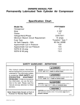
1. The amperage rating ofthe electrical box isadequate.
Refer to the Specification Chart in the Outfit Parts
Bulletin for your compressor.
2. The supply line has the same electdcal characteris-
tics (voltage, cycle, phase) as the motor.
Widng must be such that full motor nameplate voltage
plus or minus 10% is available at the motor terminals
during starting. Refer to local codes for recommended
wire sizes for correct wire size and maximum wire run;
undersize wire causes high amp draw and overheating to
the motor.
Electrical wiring must be located away from hot
surfaces such as manifold assembly, compres-
sor outlet tubes, beads, or cylinders.
OPERATING PROCEDURES
1. Before attaching air hose or acoessodes, make sure pressor is ready for use.
the OFF/AUTO lever is set to "OFF" and the air
regulator or globe valve is closed.
2. Attach hose and accessories.
6. Always operate the air compressor in well-ventilated
areas; free ofgasoline orothersolvent vapors. Do not
operate the compressor near the spray area.
TOO MUCH AIR PRESSURE CREATES A HAZ-
ARDOUS RISK OF BURSTING. CAREFULLY
FOU.OW STEPS 3 AND 5 EACH TIME THE
COMPRESSOR IS USED.
Compressed air from the outfit may contain
water condensation. Do not spray until-
tered air at an item that could be damaged.
Some air operated tools or devices may
require filtered air. Read the instructions
for the air tool or device.
3. Check the manufacturer's maximum pressure rating
for air tools and accossodes. The regulator outlet
pressure must never exceed the maximum pressure
rating. If your compressor is not supplied with a
regulator with gauge, install one before using acces-
sories.
4. Turn the OFF/AUTO leverto"AUTO" and allowtank
pressure to build. Motor will stopwhen tank pressure
reaches =cut-out" pressure.
5. Openthe regulatorbytuming it clockwise. Adjustthe
regulator to the correct pressure setting. Your com-
When you are finished:
7, Setthe"OFFIAUTO"leverto=OFF ".
8. Turn the regulator counterclockwise and set the
outlet pressure to zero.
9. Removethe airtool or accessory.
10. Open the regulator and allow the air to slowly bleed
from the tank. Close the regulator when tank pres-
sure is approximately 20 psi.
11. Drain waterfrem airtank.
WATER WILL CONDENSE IN THE AIR TANK.
IF NOT DRAINED, WATER WILL CORRODE
AND WEAKEN THE AIR TANK CAUSING A
RISK OF AIR TANK RUPTURE.
With tank pressure at approximately 20 psi, open the
drain cock or drain valve.
NOTE:
If drain cock valve is plugged, release all air
pressure. The valve can then be removed,
cleaned, then reinstalled.
12. After the water has been drained, close the drain
cock or drain valve. The air compressor can nowbe
stored.
9
MAINTENANCE
iiiii
UNIT CYCLES AUTOMATICALLY WHEN POWER IS ON. WHEN DOING MAINTENANCE, YOU MAY BE
EXPOSED TO VOLTAGE SOURCES, COMPRESSED AIR OR MOVING PARTS. PERSONAL INJURIES CAN
OCCUR. BEFORE PERFORMING ANY MAINTENANCE OR REPAIR, UNPLUG THE COMPRESSOR AND
BLEED OFF ALL AIR PRESSURE.
ALLMAINTENANCEAND REPAIROPERATIONSNOTLISTEDMUSTBEDONEBYQUALIFIEDSERVICEPERSONNEL.
Air Filter - Inspection and Replacement Check Valve Replacement - Portable
Compressors
Risk of burn.
Hot surfaces. Compressor
heads are exposed when filter cover is
removed. Allow compressor to cool prior
to servicing. _
Keep the air filter clean at all times. Do not operate the
compressor with the air filter removed.
A dirty air filter will not allowthe compressor tooperate at
full capacity. Before you use the compressor, check the
air filter to be sure it is clean.
Check Valve - Replacement - Stationary
(Permanently Mounted) Compressors
1. Release all air pressure frcm air tank and disconnect
outfitfrom supply circuit.
2. Remove rear shroud.
3. Remove tubes and compression fittings at the tee
and remove the tee from the check valve.
4. Remove the pressure release tube and fitting from
the check valve.
5. Unscrew from the check valve (turn counterclock-
wise) using a socket wrench.
6. The check valve may be cleaned with a solvent, such
as paint and varnish remover.
7. Apply sealant to the check valve threads. Reinstall
the check valve (turn clockwise). DO NOT
OVERTIGHTEN.
8. Replace the pressure release tube, fitting and tee.
9. Replace the outlet tubes and tighten fittings.
10, Replace the shroud.
11. Connect compressor to supply circuit,
Risk of personal injury. Mainfold assembly
contains compressed air which can be hxTardous.
Manifold gets hot during operation.
Before servicing:
Unplug or disconnect electdcel supply to
compressor.
-Bleed tank of pressure.
Allow compressor to cool.
t. Release all air pressure from air tank and unplug
outfit.
2. Remove console cover.
3. Loosen lower ouUettube nutsthat secure outtettubes
to the upper manifold section.
4. Remove the six screws secudng the upper manifold
section to the lower section.
5. Lift upper manifold assembly and invert so that the
flapper valve and o-dng are exposed.
6. Remove the two small screws secudng the flapper
valve and restdctor.
7. Replace flapper valve and re-assemble restdctorand
two screws.
8. Assemble upper manifold assembly to the lower
section. Make sure the o-dng is retained in the upper
section as itis inverted and the outlet tube slides into
the upper section. Tighten six screws.
9. Tighten lower outfit tube nuts.
10. Replace console cover.
Safety Valve - Inspection
If the safety valve does not work properly,
over-pressurization may occur, causing air
tank rupture or an explosion. Before starting
compressor, pull the ring on the safety valve
to make sure that the safety valve operates
fTeely.If the valve is stuck or does not operate
smoothly, it must be replaced with the same
type of valve.
10
MAINTENANCE (cont'd)
The motor has an automatic msat thermal overload
protector. If the motor overheats for any reason, the
ovedoad protector will shut off the motor. The motor
must be allowed to cool down before restarting. The
compressor will automatically restart after the motor
cools.
If the ovedoed protector shuts the motor off frequently,
check for a possible voltage problem. Lowvoltage can
also be suspected when:
1. The motor does not get up to full power or speed.
2. Fuses blow out when starting the motor; lights
dim and remain dim when motor isstarted and is
running.
Storage
Before you store the air compressor, make sure you do
the following:
1. Review the =Maintenance" and "Operating Proce-
dures" sections and perform maintenance as neces-
sary. Be sure to drain water from the air tank.
2. Protect the electrical cordand air hose from damage
(such as being stepped on or run over). Wind them
loosely around the compressor handle.
Store the air compressor in a clean and dry location.
11
Illllllll
TROUBLESHOOTING GUIDE
PERFORMING REPAIRS MAY EXPOSE VOLTAGE SOURCES, MOVING PARTS OR COM-
PRESSED AIR SOURCES. PERSONAL INJURY MAY OCCUR. PRIOR TO ATTEMPTING ANY
REPAIRS, UNPLUG THE COMPRESSOR AND BLEED OFF TANK AIR PRESSURE.
PROBLEM
Excessivetank pressure- safety
valve pops off.
CAUSE CORRECTION
Pressureswitchdoesnotshutoffmctor
when compressorreaches "cut-out"
pressure.
Movethepressureswitchlevertothe'OFF =position.
Iftheoutt'rtdoesn'tshutoff,andtheelectricalcontacts
areweldedtogether, replacethe pressureswitch.
Pressure switch'cut-out" too high. Return the outfit to Sears Service Center to check
and adjust, or replace switch.
Air leaks at fittings. Tube fittings are not tight enough. Tighten fittings where air can be heard escaping,
Check t'rttings with soapy water solution, DO NOT
OVER-TGHTEN.
Airleaks atorinsidecheckvaive, Defective or dirty check valve.
Air leaks at pressure switch re-
lease valve.
Defective pressure switch release
valve.
Defective check valve.
Defectiveair tank.Airleaks inairtankoratairtank
welds.
A defective check valve results in a constant air leak
at the pressure release valve where there ispressure
in thetank and the compressor is shut off. Remove
and clean or replace check valve.
Remove and replace the release valve.
Ifthe contacts are good, checkto see ifthe pin inthe
bottom of the pressure release valve is stuck. If it
does not move freely, replace the valve,
A defective check valve results in a constant air leak
at the pressure release valve when there is pressure
in thetank and the compressor is shut off. Remove
and clean or replace check valve.
Airtank must bereplaced. Do not repairtheleak.
DO NOT DRILL INTO, WELD OR OTHERWISE
MODIFY AIR TANK OR IT WILL WEAKEN, THE
TANK CAN RUPTURE OR EXPLODE.
Air leaks between head and Leaking seal. Torque head screws to 8 ft. Ibs. If this does not
valve plate, stop leak, replace seal.
tt is normal for"some" pressure drop
to occur.
Pressure reading on the regu-
lated pressure gauge drops
when an accessory is used.
If there is an excessive amount of pressure drop
when the accessory is used, adjust the regulator
following the instructions on page 6.
NOTE
Adjust the regulated pressure under flow condi-
lions (while accesory is being used).
12
TROUBLESHOOTING GUIDE (Continued)
PROBLEM CAUSE CORRECTION
Air leak from safety valve. Possible defect in safety valve. Operate safety valve manually by puningon ring. tf
valve still leaks, it should be replaced.
Knocking Noise Remove and clean, or replace,
Decrease amount of air usage,Compressor is not supplying
enough air to operate accesso-
ries.
Motorwillnotrunor restart.
Regulator knob continuous air
leak, Regulator will not shut off
at air outlet.
Defective check valve.
Prolonged excessive use of air.
Compressor isnot large enough forair
requirement.
Restricted air intake filter,
Hole in hose,
Check valve restricted.
Airleaks.
Motor overload protection switch has
tripped.
Tank pressure exceeds pressure
switch"cut-in" pressure.
Wrong gauge wire or length of exten-
sion cord.
Check valve stuck open.
Loose electrical connections.
Possible defective motor or capacitor.
Paint spray on internal motor parts.
Fuse blown, circuit breaker tripped.
Pressure release valve on pressure
switch has not unloaded head pres-
sure.
Broken exhaust valve.
Dirty or damaged regulator internal
)arts.
Check the accessory air requirement. If it is higher
than the SCFM or pressure supplied by your air
compressor, you need a larger compressor.
Clean or replace air intake filter. Do not operate the
air compressor in the paint spray area.
Check and replace if required.
Remove and clean, or replace.
Tighten f_ings. (See Air Leaks Section of Trou-
bleshooting Guide,)
Let motor cool off and overload switch will automati-
cally reset.
Motor will start automaticatly when tank pressure
drops below "cut-in" pressure of pressure switch.
Check for proper gauge wire and cord length.
Remove and clean, or replace.
Check wiring connection inside pressure switch and
terminal box area.
Return to Sears Service Center for inspection or
replacement, if necessary.
Have checked at Sears Service Center. Do not
operatethe compressorinthepaintsprayarea.See
flammablevaporwarning,
1_ Check fuse box for blown fuse and replace, if
necessary. Reset circuitbreaker,Do not usea
fuse orcircuitbreakerwithhigherratingthanthat
specifiedfor yourparticularbranchcircuit.
2. Checkfor properfuse; only"Fusetron"type T
fuses are acceptable.
3. Checkfor lowvoltageconditionsand/orproper
extensioncord,
4, Disconnecttheotherelectricalappliancesfrom
circuit or operate the compressorin its own
branchcircuit,
Bleed the line by pushing the lever on the pressure
switch tothe=ofr' position;ifthevalve doesnot open,
replace it.
Remove head and valve plate, inspect and replace
if necessary,
Clean or replace regulator, or internal parts.
13
SERVICE NOTES
14
SERVICE NOTES
m
15
_ VRS
CRAFTSMAN
SERVICE
MODEL NO.
HOW TO ORDER
REPAIR PARTS
GENERAL MANUAL FOR
PERMANENTLY LUBRICATED
TANK MOUNTED
AIR COMPRESSOR
Now that you have purchased your Sears Air Compressor, should a
need ever exist for repair parts or service, simply contact any Sears
Service Center and most Sears, Roebuck and Co. stores, Be sure to
provide all pertinent facts when you call or visit.
The model number ofyour Sears Air Compressor can be found on the
label which is located on the top of the motor cover or on the tank.
WHEN ORDERING REPAIR PARTS, ALWAYS GIVE THE FOL-
LOWING INFORMATION:
PART NUMBER PART DESCRIPTION
MODEL NUMBER NAME OF ITEM
All parts listed may be ordered from any Sears Service Center and
most Sears stores.
If the parts you need are not stocked locally, your order will be
electronically transmitted to a Sears Repair Parts Distribution Center
for handling.
Sears, Roebuck and Co., Chicago, IL 60684 U.S.A.
  • Page 1 1
  • Page 2 2
  • Page 3 3
  • Page 4 4
  • Page 5 5
  • Page 6 6
  • Page 7 7
  • Page 8 8
  • Page 9 9
  • Page 10 10
  • Page 11 11
  • Page 12 12
  • Page 13 13
  • Page 14 14
  • Page 15 15
  • Page 16 16

Craftsman Air Compressor Owner's manual

Category
Air compressors
Type
Owner's manual
This manual is also suitable for

Ask a question and I''ll find the answer in the document

Finding information in a document is now easier with AI