Dell Studio XPS 435MT User manual
- Category
- Supplementary music equipment
- Type
- User manual
This manual is also suitable for

DellStudioXPS™435MTServiceManual
Model DCMMF
Notes, Cautions, and Warnings
Information in this document is subject to change without notice.
©2008DellInc.Allrightsreserved.
Reproduction of these materials in any manner whatsoever without the written permission of Dell Inc. is strictly forbidden.
Trademarks used in this text: Dell, the DELL logo, and Studio XPS are trademarks of Dell Inc.; Intel is a registered trademark and SpeedStep is a trademark of Intel Corporation in
the U.S. and other countries.; Microsoft and Windows are either trademarks or registered trademarks of Microsoft Corporation in the United States and/or other countries.
Other trademarks and trade names may be used in this document to refer to either the entities claiming the marks and names or their products. Dell Inc. disclaims any
proprietary interest in trademarks and trade names other than its own.
October2008Rev.A00
Technical Overview
Before You Begin
Replacing the Computer Cover
Replacing the Front Panel
Replacing Memory Module(s)
Replacing a PCI Express Card
Replacing Drives
Replacing the Front I/O Panel
Replacing Fans
Replacing the Processor
Replacing the System Board
Replacing the Battery
Replacing the Power Supply
Replacing the Rubber Foot
System Setup
NOTE: A NOTE indicates important information that helps you make better use of your computer.
CAUTION: A CAUTION indicates either potential damage to hardware or loss of data and tells you how to avoid the problem.
WARNING: A WARNING indicates a potential for property damage, personal injury, or death.

Back to Contents Page
Replacing the Badge Back Light
DellStudioXPS™435T/9000ServiceManual
1. Follow the procedures in Before You Begin.
2. Remove the computer cover (see Replacing the Computer Cover).
3. Remove the front panel (see Replacing the Front Panel).
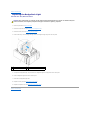
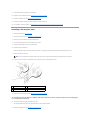
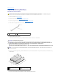
4. Press the tabs away from the badge back light and lift the badge back light away from the front panel.
5. To replace the badge back light, align the holes in the badge back light to the projections on the front panel.
6. Press the badge back light down until it clicks in place.
7. Reconnect the badge back light cable.
8. Replace the front panel (see Replacing the Front Panel).
9. Replace the computer cover (see Replacing the Computer Cover).
Back to Contents Page
WARNING: Before working inside your computer, read the safety information that shipped with your computer. For additional safety best
practices information, see the Regulatory Compliance Homepage at www.dell.com/regulatory_compliance.
1
badge back light
2
badge back light cable
3
tabs (3)

Back to Contents Page
Before You Begin
DellStudioXPS™435MTServiceManual
Technical Specifications
Recommended Tools
Turning Off Your Computer
Safety Instructions
This chapter provides procedures for removing and installing the components in your computer. Unless otherwise noted, each procedure assumes that the
following conditions exist:
l You have performed the steps in Turning Off Your Computer and Safety Instructions.
l You have read the safety information that shipped with your computer.
l A component can be replaced or—if purchased separately—installed by performing the removal procedure in reverse order.
Technical Specifications
For information on technical specifications of your computer, see the Setup Guide that shipped with your computer or see the Dell Support website at
support.dell.com.
Recommended Tools
The procedures in this document may require the following tools:
l Small flat-blade screwdriver
l Small Phillips screwdriver
l Small plastic scribe
l Flash BIOS executable update program on the Dell Support website at support.dell.com
Turning Off Your Computer
1. Shut down the operating system.
2. Ensure that the computer and all attached devices are turned off. If your computer and attached devices did not automatically turn off when you shut
down your operating system, press and hold the power button for about 4 seconds to turn them off.
Safety Instructions
Use the following safety guidelines to help protect your computer from potential damage and to help to ensure your own personal safety.
Before working inside your computer, read the safety information that shipped with your computer. For additional safety best practices information, see the
Regulatory Compliance Homepage at www.dell.com/regulatory_compliance.
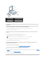
1. Ensure that the work surface is flat and clean to prevent the computer cover from being scratched.
2. Turn off your computer (see Turning Off Your Computer).
CAUTION: To avoid losing data, save and close all open files and exit all open programs before you turn off your computer.
CAUTION: Onlyacertifiedservicetechnicianshouldperformrepairsonyourcomputer.DamageduetoservicingthatisnotauthorizedbyDell™
is not covered by your warranty.
CAUTION: When you disconnect a cable, pull on its connector or on its pull-tab, not on the cable itself. Some cables have connectors with locking
tabs; if you are disconnecting this type of cable, press in on the locking tabs before you disconnect the cable. As you pull connectors apart, keep
them evenly aligned to avoid bending any connector pins. Also, before you connect a cable, ensure that both connectors are correctly oriented
and aligned.
CAUTION: To avoid damaging the computer, perform the following steps before you begin working inside the computer.

3. Disconnect all telephone or network cables from the computer.
4. Disconnect your computer and all attached devices from their electrical outlets.
5. Press and hold the power button while the system is unplugged to ground the system board.
Back to Contents Page
CAUTION: To disconnect a network cable, first unplug the cable from your computer and then unplug the cable from the network device.
CAUTION: Before touching anything inside your computer, ground yourself by touching an unpainted metal surface, such as the metal at the back
of the computer. While you work, periodically touch an unpainted metal surface to dissipate static electricity, which could harm internal
components.

Back to Contents Page
Replacing a PCI Express Card
DellStudioXPS™435MTServiceManual
Removing a PCI Express Card
Installing a PCI Express Card
Replacing the Card Retention Bracket
Configuring Your Computer After Removing or Installing a PCI Express Card
Removing a PCI Express Card
1. Uninstall the PCI Express card's driver and software from the operating system. For more information, see the Setup Guide.
2. Follow the procedures in Before You Begin.
3. Remove the computer cover (see Replacing the Computer Cover).
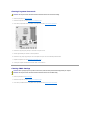
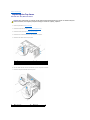
4. Remove the screw that secures the card retention bracket.
5. Lift the card retention bracket and set it aside in a secure place.
6. If applicable, disconnect any cables connected to the card.
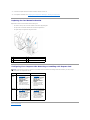
7. Press the securing tab, grasp the card by its top corners, and then ease it out of its connector.
8. If you are replacing an existing card, go to step 6 of Installing a PCI Express Card.
WARNING: Before working inside your computer, read the safety information that shipped with your computer. For additional safety best
practices information, see the Regulatory Compliance Homepage at www.dell.com/regulatory_compliance.
1
card retention bracket
2
filler bracket
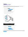
1
PCI Express x16 card
2
securing tab
3
PCI Express x1 card
4
PCI Express x1 card slot
5
PCI Express x16 card slot
CAUTION: Installing filler brackets over empty card-slot openings is necessary to maintain FCC certification of the computer. The brackets also
keep dust and dirt out of your computer.

9. Install a filler bracket in the empty card-slot opening.
10. Replace the card retention bracket (see Replacing the Card Retention Bracket).
11. Replace the computer cover (see Replacing the Computer Cover).
12. Connect the computer and devices to electrical outlets, and then turn them on.
13. To complete the removal procedure, see Configuring Your Computer After Removing or Installing a PCI Express Card.
Installing a PCI Express Card
1. Follow the procedures in Before You Begin.
2. Remove the computer cover (see Replacing the Computer Cover).
3. Remove the screw that secures the card retention bracket.
4. Lift the card retention bracket and set it aside in a secure place.
5. Remove the filler bracket to create a card-slot opening.
6. Prepare the card for installation.
See the documentation that came with the card for information on configuring, customizing, and making internal connections on the card.
7. Align the card with the connector.
8. Place the card in the connector and press down firmly. Ensure that the card is fully seated in the slot.
9. Replace the card retention bracket (see Replacing the Card Retention Bracket).
10. Connect any cables that should be attached to the card.
See the documentation for the card for information about the card's cable connections.
11. Replace the computer cover (see Replacing the Computer Cover).
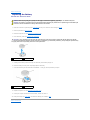
NOTE: If you are installing a PCI Express card into the x16 connector, ensure that the securing slot is aligned with the securing tab.
1
alignment bar
2
fully-seated card
3
not fully-seated card
4
alignment guide
5
bracket within slot
6
bracket caught outside of slot
CAUTION: Do not route card cables over or behind the cards. Cables routed over the cards can prevent the computer cover from closing properly
or cause damage to the equipment.

12. Connect the computer and devices to electrical outlets, and then turn them on.
13. To complete the installation, see Configuring Your Computer After Removing or Installing a PCI Express Card.
Replacing the Card Retention Bracket
Replace the screw on the card retention bracket ensuring that:
l The notch in the top of the card or filler bracket fits around the alignment guide.
l The tops of all cards and filler brackets are flush with the alignment bar.
l The guide clamps are aligned with the guide notches.
Configuring Your Computer After Removing or Installing a PCI Express Card
Back to Contents Page
1
alignment guide
2
filler bracket
3
alignment bar
4
card retention bracket
5
guide clamps (2)
6
guide notches (2)
NOTE: For information on location of connectors, see the Setup Guide. For information on installing drivers and software for your card, see the
documentation that shipped with the card.
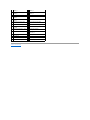
Installed
Removed
Sound
Card
1. Enter system setup (see
System Setup).
2. Go to Advanced Chipset
Features and select
Onboard Audio
Controller, and then
change the setting to
Disabled.
3. Connect the external
audio devices to the
sound card's connectors.
1. Enter system setup (see
System Setup).
2. Go to Advanced Chipset
Features and select
Onboard Audio
Controller, and then
change the setting to
Enabled.
3. Connect the external
audio devices to the
computer's back panel
connectors.
Network
Card
1. Enter system setup (see
System Setup).
2. Go to Advanced Chipset
Features and select
Onboard LAN Controller,
and then change the
setting to Disabled.
3. Connect the network
cable to the network
card's connector.
1. Enter system setup (see
System Setup).
2. Go to Advanced Chipset
Features and select
Onboard LAN Controller,
and then change the
setting to Enabled.
3. Connect the network
cable to the integrated
network connector.

Back to Contents Page
Replacing the Battery
DellStudioXPS™435MTServiceManual
1. Record all the screens in system setup (see System Setup) so that you can restore the correct settings in step 10.
2. Follow the procedures in Before You Begin.
3. Remove the computer cover (see Replacing the Computer Cover).
4. Locate the battery socket (see System Board Components).
5. Carefully press the battery release lever away from the battery and the battery will pop out.
6. Remove the battery from the system and properly dispose of the battery.
7. Insert the new battery into the socket with the side labeled "+" facing up, then snap the battery into place.
8. Replace the computer cover (see Replacing the Computer Cover).
9. Connect your computer and devices to electrical outlets, and then turn them on.
10. Enter system setup (see System Setup) and restore the settings you recorded in step 1.
Back to Contents Page
WARNING: Before working inside your computer, read the safety information that shipped with your computer. For additional safety best
practices information, see the Regulatory Compliance Homepage at www.dell.com/regulatory_compliance.
WARNING: A new battery can explode if it is incorrectly installed. Replace the battery only with the same or equivalent type recommended by the
manufacturer. Discard used batteries according to the manufacturer's instructions.
CAUTION: If you pry the battery out of its socket with a blunt object, be careful not to touch the system board with the object. Ensure that the
object is inserted between the battery and the socket before you attempt to pry out the battery. Otherwise, you may damage the system board by
prying off the socket or by breaking circuit traces on the system board.
1
battery (positive side)
2
battery release lever
1
battery (positive side)
2
battery release lever

Back to Contents Page
Replacing the Computer Cover
DellStudioXPS™435MTServiceManual
1. Follow the procedures in Before You Begin.
2. Lay your computer on its side with the computer cover facing up.
3. Open the padlock, if applicable.
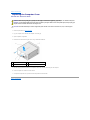
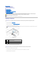
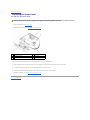
4. Remove the two screws securing the cover, using a flat-blade screwdriver.
5. Pull the cover grip towards the back of the computer, and lift the computer cover away from the computer.
6. Set the computer cover aside in a secure location.
7. To replace the computer cover, perform the removal procedure in reverse order.
Back to Contents Page
WARNING: Before working inside your computer, read the safety information that shipped with your computer. For additional safety best
practices information, see the Regulatory Compliance Homepage at www.dell.com/regulatory_compliance.
WARNING: To guard against likelihood of electric shock, laceration by moving fan blades or other unexpected injuries, always unplug your
computer from the electrical outlet before removing the cover.
CAUTION: Ensure that sufficient space exists to support the system with the cover removed—at least 30 cm (1 ft.) of desk top space.
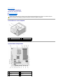
1
computer cover
2
front of the computer
3
screws (2)
4
cover grip

Back to Contents Page
Replacing the Processor
DellStudioXPS™435MTServiceManual
1. Follow the procedures in Before You Begin.
2. Remove the computer cover (see Replacing the Computer Cover).
3. Disconnect the power cables from the power connector for the processor (PWR2) and main power connector (PWR1) on the system board (see System
Board Components).
4. Remove the processor fan and heat sink assembly from the computer (see Replacing the Processor Fan and Heat Sink Assembly).
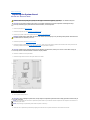
5. Press and push the release lever down and out to release it from the tab that secures it.
6. Open the processor cover.
7. Lift up the processor to remove it from the socket, place it aside in a safe and secure place.
Leave the release lever extended in the release position so that the socket is ready for the new processor.
8. Unpackthenewprocessor,becarefulnottotouchtheundersideoftheprocessor.
WARNING: Before working inside your computer, read the safety information that shipped with your computer. For additional safety best
practices information, see the Regulatory Compliance Homepage at www.dell.com/regulatory_compliance.
CAUTION: Do not perform the following steps unless you are familiar with hardware removal and replacement. Performing these steps
incorrectly could damage your system board. For technical service, see the Setup Guide.
WARNING: Despite having a plastic shield, the processor fan and heat sink assembly may be very hot during normal operation. Ensure that it has
had sufficient time to cool before you touch it.
NOTE: Unless a new heat sink is required for the new processor, reuse the original heat sink assembly when you replace the processor.
1
processor cover
2
processor
3
socket
4
release lever
CAUTION: When removing or replacing the processor, do not touch any of the pins inside the socket or allow any objects to fall on the pins in the
socket.
CAUTION: Ground yourself by touching an unpainted metal surface on the back of the computer.

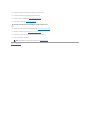
9. If the release lever on the socket is not fully extended, move it to that position.
10. Orient the front and back alignment-notches on the processor with the front and back alignment-notches on the socket.
11. Align the pin-1 corners of the processor and socket.
12. Set the processor lightly in the socket and ensure that the processor is positioned correctly.
13. When the processor is fully seated in the socket, close the processor cover.
14. Pivot the socket release lever back towards the socket, and snap it into place to secure the processor.
15. Clean the thermal grease from the bottom of the heat sink.
16. Apply the new thermal grease to the top of the processor.
17. Replace the processor fan and heat sink assembly (see Replacing the Processor Fan and Heat Sink Assembly).
18. Connect the power cables to the power for processor connector (PWR2) and the main power connector (PWR1) on the system board (see System Board
Components).
19. Replace the computer cover (see Replacing the Computer Cover).
20. Connect your computer and devices to electrical outlets, and then turn them on.
1
processor cover
2
tab
3
alignment notch (2)
4
processor
5
socket
6
center cover latch
7
release lever
8
processor pin-1 indicator
CAUTION: You must position the processor correctly in the socket to avoid permanent damage to the processor and the computer when you turn
on the computer.
CAUTION: Socket pins are delicate. To avoid damage, ensure that the processor is aligned properly with the socket, and do not use excessive
force when you replace the processor. Be careful not to touch or bend the pins on the system board.
CAUTION: To avoid damage, ensure that the processor aligns properly with the socket, and do not use excessive force when you install the
processor.
NOTE: Ensure that the tab on the processor cover is positioned underneath the center cover latch on the socket.
CAUTION: Ensure that you apply new thermal grease. New thermal grease is critical for ensuring adequate thermal bonding, which is a
requirement for optimal processor operation.
CAUTION: Ensure that the processor fan and heat sink assembly is correctly seated and secure.


Back to Contents Page
Replacing Drives
DellStudioXPS™435MTServiceManual
Replacing a Hard Drive
Replacing an Optical Drive
Replacing the FlexDock
Removing the FlexDock Break-Away Metal Plate
Replacing the FlexDock Drive Inserts
Replacing the Drive Panel Insert
Replacing a Hard Drive
1. Follow the procedures in Before You Begin.
2. Remove the computer cover (see Replacing the Computer Cover).
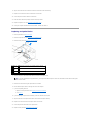
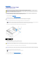
3. Disconnect the power and data cables from the hard drive.
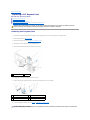
4. Remove the four screws securing the hard drive to the chassis.
5. Slide the drive out towards the back of the computer.
6. To replace the hard drive, check the documentation for the drive to verify that it is configured for your computer.
7. Slide the hard drive into the hard drive bay.
WARNING: Before working inside your computer, read the safety information that shipped with your computer. For additional safety best
practices information, see the Regulatory Compliance Homepage at www.dell.com/regulatory_compliance.
NOTE: The system board does not support IDE devices.
NOTE: The 3.5-inch FlexDock is not interchangeable with the hard drive carrier.
CAUTION: If you are replacing a hard drive that contains data you want to keep, back up your files before you begin this procedure.
NOTE: If you are not replacing the hard drive at this time, disconnect the other end of the data cable from the system board and set it aside. You
can use the data cable to install a hard drive at a later time.
1
screws
(4)
2
system board connector (any available connector SATA0,
SATA1, SATA2, and SATA3)
3
data
cable
4
power cable
5
hard
drive
CAUTION: Ensure that you do not scratch the hard disk's circuit board, while removing or replacing the hard drive.

8. Align the four screw holes on the hard drive with the screw holes on the hard drive bay.
9. Replace the four screws that secure the hard drive to the chassis.
10. Connect the power and data cables to the hard drive.
11. Ensure that all the cables are properly connected and firmly seated.
12. Replace the computer cover (see Replacing the Computer Cover).
13. Connect your computer and devices to electrical outlets, and then turn them on.
Replacing an Optical Drive
1. Follow the procedures in Before You Begin.
2. Remove the computer cover (see Replacing the Computer Cover).
3. Remove the front panel (see Replacing the Front Panel).
4. Disconnect the power cable and the data cable from the back of the optical drive.
5. Remove the two screws securing the optical drive to the chassis.
6. Push and slide the optical drive out through the front of the computer.
7. If you are not replacing the drive:
a. Replace the drive panel insert (see Replacing the Drive Panel Insert).
b. Go to step 12.
8. If you are replacing the optical drive or installing a new one, slide the drive into place.
9. Align the screw holes in the optical drive with the screw holes in the optical drive bay.
10. Replace the two screws that secure the optical drive to the chassis.
11. Connect the power and data cables to the optical drive.
12. Replace the front panel (see Replacing the Front Panel).
1
screws (2)
2
system board connector (any available connector SATA0,
SATA1, SATA2, and SATA3)
3
power
cable
4
data cable
5
optical
drive
NOTE: If you are uninstalling the only optical drive in your computer and will not replace it at this time, disconnect the data cable from the system
board and set it aside.

13. Replace the computer cover (see Replacing the Computer Cover).
14. Connect your computer and devices to their electrical outlets, and turn them on.
Replacing the FlexDock
1. Follow the procedures in Before You Begin.
2. Remove the computer cover (see Replacing the Computer Cover).
3. Remove the front panel (see Replacing the Front Panel).
4. Disconnect the FlexDock USB cable from the back of the FlexDock and from the FlexDock USB connector (F_USB4) on the system board (see System
Board Components).
5. Remove the two screws securing the FlexDock.
6. Slide the FlexDock out through the front of the computer.
7. If you are not replacing the FlexDock, replace the drive panel insert (see Replacing the Drive Panel Insert) and proceed with step step 13.
8. If you are installing a new FlexDock:
a. Remove the drive panel insert, if applicable (see Replacing the Drive Panel Insert).
b. Remove the FlexDock break-away metal plate, if applicable (see Removing the FlexDock Break-Away Metal Plate).
c. Remove the FlexDock from its packaging.
9. Gently slide the FlexDock into place in the FlexDock slot.
10. Align the screw holes on the FlexDock with the screw holes on the FlexDock slot.
11. Replace the two screws that secure the FlexDock.
12. Connect the FlexDock USB cable to the back of the FlexDock and to the FlexDock USB connector (F_USB4) on the system board (see System Board
Components).
13. Replace the front panel (see Replacing the Front Panel).
NOTE: If you installed a new drive, see the documentation that came with the drive for instructions on installing any software required for drive
operation.
1
custom screws (2)
2
FlexDock USB connector (F_USB4)
3
FlexDock USB cable
4
FlexDock
NOTE: Ensure that the FlexDock is installed before the FlexDock cable is connected.

14. Replace the computer cover (see Replacing the Computer Cover).
15. Connect your computer and devices to electrical outlets, and then turn them on.
Removing the FlexDock Break-Away Metal Plate
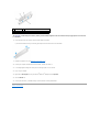
Align the tip of a Phillips screwdriver with the slot on the break-away metal plate and rotate the screwdriver outwards to break and remove the metal plate.
Replacing the FlexDock Drive Inserts
1. Remove the front panel (see Replacing the Front I/O Panel).
2. Gently press on the insert lever inward to release the lock.
3. Pull the FlexDock drive insert away from the front panel.
4. To replace the FlexDock drive insert, align the FlexDock drive insert in place.
5. Push the insert lever towards the front panel till it snaps into place.
Replacing the Drive Panel Insert
Align the drive panel insert along the edges of the empty slot of the FlexDock or an optical drive and push the panel insert until it locks into place.
CAUTION: To comply with FCC regulations, it is recommended that you replace the FlexDock drive insert whenever the FlexDock is removed from
the computer.
1
front panel
2
insert lever
3
FlexDock drive insert


Back to Contents Page
Replacing Fans
DellStudioXPS™435MTServiceManual
Replacing the Chassis Fan
Replacing the Processor Fan and Heat Sink Assembly
Replacing the Chassis Fan
1. Follow the procedures in Before You Begin.
2. Remove the computer cover (see Replacing the Computer Cover).
3. Disconnect the chassis fan cable from the system board fan connector (AUX_FAN1).
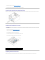
4. Remove the four screws securing the chassis fan.
5. Lift the chassis fan away from the computer.
6. To replace the chassis fan, slide it in place towards the back of the computer.
7. Replace the four screws that secure the chassis fan.
8. Connect the chassis fan cable to the system board fan connector (AUX_FAN1).
9. Replace the computer cover (see Replacing the Computer Cover).
Replacing the Processor Fan and Heat Sink Assembly
1. Follow the procedures in Before You Begin.
2. Remove the computer cover (see Replacing the Computer Cover).
3. Disconnect the processor fan cable from the CPU_FAN connector on the system board (see System Board Components).
WARNING: Before working inside your computer, read the safety information that shipped with your computer. For additional safety best
practices information, see the Regulatory Compliance Homepage at www.dell.com/regulatory_compliance.
CAUTION: Do not touch the fan blades when you are removing the chassis fan. This could damage the fan.
1
screws (4)
2
chassis fan
WARNING: Despite having a plastic shield, the processor fan and heat sink assembly may be very hot during normal operation. Ensure that it has
had sufficient time to cool before you touch it.
CAUTION: The processor fan and heat sink assembly is a single unit. Do not try to remove the fan separately.

4. Carefully move away any cables that are routed over the processor fan and heat sink assembly.
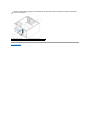
5. Loosen the four captive screws securing the processor fan and heat sink assembly.
6. Lift the processor fan and heat sink assembly out of the computer, and set it aside.
7. To replace the processor fan and heat sink assembly, clean the thermal grease from the bottom of the heat sink.
8. Apply new thermal grease to the top of the processor.
9. Align the four captive screws on the processor fan and heat sink assembly with the holes on the system board.
10. Tighten the four captive screws that secure the processor fan and heat sink assembly.
11. Connect the processor fan and heat sink assembly cable to the CPU_FAN connector on the system board (see System Board Components).
12. Replace the computer cover (see Replacing the Computer Cover).
13. Connect your computer and devices to electrical outlets, and turn them on.
Back to Contents Page
CAUTION: To ensure maximum cooling for the processor, do not touch the heat transfer areas on the processor heat sink. The oils in your skin
can reduce the heat transfer capability of the thermal pads.
CAUTION: When you remove the processor fan and heat sink assembly, lay it upside down or on its side to avoid damaging the heat sink thermal
interface.
1
processor fan and heat sink assembly
2
captive screws (4)
3
processor fan and heat sink assembly cable
NOTE: The processor fan and heat sink assembly in your computer may not look exactly like the one shown in the illustration above.
CAUTION: Ensure that you apply new thermal grease. New thermal grease is critical for ensuring adequate thermal bonding, which is a
requirement for optimal processor operation.
NOTE: Ensure that the processor fan and heat sink assembly is correctly seated and secure.

Back to Contents Page
Replacing the Front Panel
DellStudioXPS™435MTServiceManual
1. Follow the procedures in Before You Begin.
2. Remove the computer cover (see Replacing the Computer Cover).
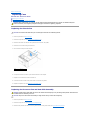
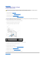
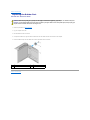
3. Grasp and lift the front panel grips one at a time to release it from the front of the computer.
4. Rotate and pull the front panel away from the front of the computer to release the front panel clamps from the clamp insert.
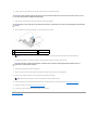
5. To replace the front panel, align and insert the front panel clamps into the clamp insert.
6. Rotate the front panel towards the computer until it snaps into place on the front of the computer.
7. Replace the computer cover (see Replacing the Computer Cover).
Back to Contents Page
WARNING: Before working inside your computer, read the safety information that shipped with your computer. For additional safety best
practices information, see the Regulatory Compliance Homepage at www.dell.com/regulatory_compliance.
1
front panel grips (3)
2
front panel
3
front panel clamps (3)
4
clamp insert
5
back of the computer
Page is loading ...
Page is loading ...
Page is loading ...
Page is loading ...
Page is loading ...
Page is loading ...
Page is loading ...
Page is loading ...
Page is loading ...
Page is loading ...
Page is loading ...
Page is loading ...
Page is loading ...
Page is loading ...
Page is loading ...
Page is loading ...
Page is loading ...
Page is loading ...
Page is loading ...
Page is loading ...
-
 1
1
-
 2
2
-
 3
3
-
 4
4
-
 5
5
-
 6
6
-
 7
7
-
 8
8
-
 9
9
-
 10
10
-
 11
11
-
 12
12
-
 13
13
-
 14
14
-
 15
15
-
 16
16
-
 17
17
-
 18
18
-
 19
19
-
 20
20
-
 21
21
-
 22
22
-
 23
23
-
 24
24
-
 25
25
-
 26
26
-
 27
27
-
 28
28
-
 29
29
-
 30
30
-
 31
31
-
 32
32
-
 33
33
-
 34
34
-
 35
35
-
 36
36
-
 37
37
-
 38
38
-
 39
39
-
 40
40


Dell Studio XPS 435MT User manual
- Category
- Supplementary music equipment
- Type
- User manual
- This manual is also suitable for
Ask a question and I''ll find the answer in the document
Finding information in a document is now easier with AI
Related papers
-
Dell 540 User manual
-
Dell Studio XPS 435T / 9000 Owner's manual
-
Dell DCDR01 User manual
-
-
-
Dell 19 User manual
-
Dell OptiPlex 755 Owner's manual
-
-
-
Other documents
-
Motion Computing Tablet PC User manual
-
-
Gateway Tablet PC User manual
-
-
Alpine M1400 User manual
-
-
Zebra J3400 Owner's manual
-
-
Alienware m15 R2 User manual
-
Alienware 17 R4 User manual