
H81MG Setup Manual
FCC Information and Copyright
This equipment has been tested and found to comply with the limits of a Class B
digital device, pursuant to Part 15 of the FCC Rules. These limits are designed
to provide reasonable protection against harmful interference in a residential
installation. This equipment generates, uses, and can radiate radio frequency
energy and, if not installed and used in accordance with the instructions, may
cause harmful interference to radio communications. There is no guarantee that
interference will not occur in a particular installation.
The vendor makes no representations or warranties with respect to the contents
here and specially disclaims any implied warranties of merchantability or fitness
for any purpose. Further the vendor reserves the right to revise this publication
and to make changes to the contents here without obligation to notify any party
beforehand.
Duplication of this publication, in part or in whole, is not allowed without first
obtaining the vendor’s approval in writing.
The content of this user’s manual is subject to be changed without notice and we
will not be responsible for any mistakes found in this user’s manual. All the brand
and product names are trademarks of their respective companies.
Dichiarazione di conformità
sintetica
Ai sensi dell’art. 2 comma 3 del D.M.
275 del 30/10/2002
Si dichiara che questo prodotto è
conforme alle normative vigenti e
soddisfa i requisiti essenziali richiesti
dalle direttive
2004/108/CE, 2006/95/CE e
1999/05/CE
quando ad esso applicabili
Short Declaration of conformity
We declare this product is complying
with the laws in force and meeting all
the essential requirements as specified
by the directives
2004/108/CE, 2006/95/CE and
1999/05/CE
whenever these laws may be applied

Table of Contents
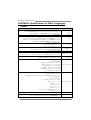
Chapter 1: Introduction .........................................................................1
1.1 Before You Start......................................................................... 1
1.2 Package Checklist..................................................................... 1
1.3 Motherboard Specifications....................................................... 2
1.4 Rear Panel Connectors ............................................................. 3
1.5 Motherboard Layout .................................................................. 4
Chapter 2: Hardware Installation ..........................................................5
2.1 Install Central Processing Unit (CPU) ....................................... 5
2.2 Install a Heatsink ....................................................................... 7
2.3 Connect Cooling Fans............................................................... 8
2.4 Install System Memory .............................................................. 9
2.5 Expansion Slots....................................................................... 10
2.6 Jumper Setting ........................................................................ 12
2.7 Headers & Connectors ............................................................ 13
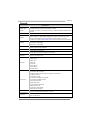
Chapter 3: UEFI BIOS & Software.......................................................18
3.1 UEFI BIOS Setup .................................................................... 18
3.2 BIOS Update ........................................................................... 18
3.3 Software................................................................................... 22
Chapter 4: Useful Help.........................................................................29
4.1 Driver Installation..................................................................... 29
4.2 AMI BIOS Beep Code.............................................................. 30
4.3 Troubleshooting....................................................................... 30
Appendix: Specifications in Other Languages .................................32
Arabic ......................................................................................................... 32
French ........................................................................................................ 33
German....................................................................................................... 34
Italian.......................................................................................................... 35
Japanese.................................................................................................... 36
Polish.......................................................................................................... 37
Portuguese ................................................................................................. 38
Russian....................................................................................................... 39
Spanish....................................................................................................... 40

H81MG
1
CHAPTER 1: INTRODUCTION
1.1 Before You Start
Thank you for choosing our product. Before you start installing the
motherboard, please make sure you follow the instructions below:
Prepare a dry and stable working environment with sufficient
lighting.
Always disconnect the computer from power outlet before
operation.
Before you take the motherboard out from anti-static bag,
ground yourself properly by touching any safely grounded
appliance, or use grounded wrist strap to remove the static
charge.
Avoid touching the components on motherboard or the rear
side of the board unless necessary. Hold the board on the
edge, do not try to bend or flex the board.
Do not leave any unfastened small parts inside the case after
installation. Loose parts will cause short circuits which may
damage the equipment.
Keep the computer from dangerous area, such as heat
source, humid air and water.
The operating temperatures of the computer should be 0 to
45 degrees Celsius.
To avoid injury, be careful of:
Sharp pins on headers and connectors
Rough edges and sharp corners on the chassis
Damage to wires that could cause a short circuit
1.2 Package Checklist
; Serial ATA Cable x2
; Rear I/O Panel for ATX Case x1
; Installation Guide x1
; Fully Setup Driver DVD x1
Note: The package contents may be different due to the sales region or models in which it was
sold. For more information about the standard package in your region, please contact your dealer
or sales representative.

Motherboard Manual
2
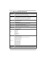
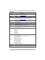
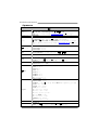
1.3 Motherboard Specifications
Specifications
CPU Support
Socket 1150 for Intel® Core i7 / i5 / i3 / Pentium / Celeron processor
Maximum CPU TDP (Thermal Design Power): 95Watt
* Please refer to
www.biostar.com.tw for CPU support list.
Chipset INTEL® H81
Memory
Supports Dual Channel DDR3 1066/ 1333/ 1600
2 x DDR3 DIMM Memory Slot, Max. Supports up to 16 GB Memory
Each DIMM supports non-ECC 512MB/ 1/ 2/ 4/ 8 GB DDR3 module
* Please refer to
www.biostar.com.tw for Memory support list.
Storage
INTEL® H81, Supports AHCI
2x SATA 6Gb/s Connector
2x SATA 3Gb/s Connector
LAN
Realtek RTL 8111G
10/ 100/ 1000 Mb/s auto negotiation, Half / Full duplex capability
Audio Codec
ALC892, 7.1 Channels, High Definition Audio
(2-channel output is from front audio header)
USB
2x USB 3.0 port (2 on rear I/Os)
6x USB 2.0 port (2 on rear I/Os and 4 via internal headers)
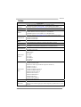
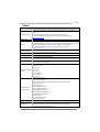
Expansion Slots
2x PCIe 2.0 x1 Slot
1x PCIe 2.0 x16 Slot (x16)
Rear I/Os
1x PS/2 Mouse
1x PS/2 Keyboard
1x VGA Port
1x DVI Port
1x LAN port
2x USB 2.0 Port
2x USB 3.0 Port
3x Audio Jack
Internal I/Os
2x SATA 6.0Gb/s Connector
2x SATA 3.0Gb/s Connector
2x USB 2.0 Header (each header supports 2 USB 2.0 ports)
1x 4-Pin Power Connector
1x 24-Pin Power Connector
1x CPU Fan Connector
1x System Fan Connector
1x Front Panel Header
1x Front Audio Header
1x Clear CMOS Header
1x Serial Port Header
1x S/PDIF out Connector
1x Printer Port Header
Form Factor ATX Form Factor, 226 mm x 174 mm
OS Support
Windows 7/ 8
Biostar reserves the right to add or remove support for any OS with or without notice.

H81MG
3
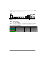
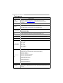
1.4 Rear Panel Connectors
Note1: DVI-D & VGA ports only work with an Intel® integrated Graphics Processor.
Note2: Maximum resolution:
DVI: 1920 x 1200 @60Hz
VGA: 1920 x 1200 @60Hz
Note3: To configure 7.1-channel audio, you have to use a chassis with HD front panel audio
module and enable the multi-channel audio feature through O.S. Audio Utility.
The 2/ 4/ 5.1/7.1-channel configuration
Port 2-channel 4-channel 5.1 channel 7.1 channel
Blue (Rear Panel) Line In Rear Speaker Out Rear Speaker Out Rear Speaker Out
Green (Rear Panel) Line Out Front Speaker Out Front Speaker Out Front Speaker Out
Pink (Rear Panel) Mic In Mic In Center/Subwoofer Out Center/Subwoofer Out
Green (Front Panel) -- -- -- Side Speaker Out

Motherboard Manual
4
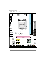
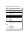
1.5 Motherboard Layout
Note: ■ represents the 1
st
pin.

H81MG
5
CHAPTER 2: HARDWARE INSTALLATION
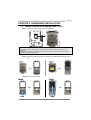
2.1 Install Central Processing Unit (CPU)
Step 1: Locate the CPU socket on the motherboard
Note1: Remove Pin Cap before installation, and make good preservation for future use. When
the CPU is removed, cover the Pin Cap on the empty socket to ensure pin legs won’t be
damaged.
Note2: The motherboard might equip with two different types of pin cap. Please refer below
instruction to remove the pin cap.
Step 2: Pull the socket locking lever out from the socket and then raise the lever
up.
Step 3: Remove the Pin Cap.

Motherboard Manual
6
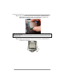
Step 4: Hold processor with your thumb and index fingers, oriented as shown.
Align the notches with the socket. Lower the processor straight down
without tilting or sliding the processor in the socket.
Note1: The LGA1155 CPU is not compatible with LGA 1150 socket. Do not install a LGA 1155 CPU
on the LGA 1150 socket.
Note2: The CPU fits only in one correct orientation. Do not force the CPU into the socket to prevent
damaging the CPU.
Step 5: Hold the CPU down firmly, and then lower the lever to locked position to
complete the installation.

H81MG
7
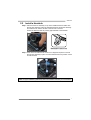
2.2 Install a Heatsink
Step 1: Place the CPU fan assembly on top of the installed CPU and make sure
that the four fasteners match the motherboard holes. Orient the assembly
and make the fan cable is closest to the CPU fan connector.
Ensure the fastener slots are pointing perpendicular to the heatsink.
Step 2: Press down two fasteners at one time in a diagonal sequence to secure
the CPU fan assembly in place. As each fastener locks into position a click
should be heard.
Note1: Do not forget to connect the CPU fan connector.
Note2: For proper installation, please kindly refer to the installation manual of your CPU heatsink.

Motherboard Manual
8
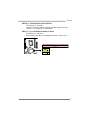
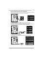
2.3 Connect Cooling Fans
These fan headers support cooling-fans built in the computer. The fan cable and
connector may be different according to the fan manufacturer.
CPU_FAN1: CPU Fan Header
Pin Assignment
1 Ground
2 +12V
3 FAN RPM rate sense
4 Smart Fan Control (By Fan)
SYS_FAN1: System Fan Header
Pin Assignment
1 Ground
2 +12V
3 FAN RPM rate sense
Note: CPU_FAN1, SYS_FAN1 support 4-pin and 3-pin head connectors. When connecting with
wires onto connectors, please note that the red wire is the positive and should be connected to
pin#2, and the black wire is Ground and should be connected to pin#1(GND).

H81MG
9
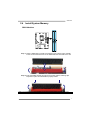
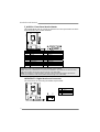
2.4 Install System Memory
DDR3 Modules
Step 1: Unlock a DIMM slot by pressing the retaining clips outward. Align a DIMM
on the slot such that the notch on the DIMM matches the break on the slot.
Step 2: Insert the DIMM vertically and firmly into the slot until the retaining clips
snap back in place and the DIMM is properly seated.
Note: If the DIMM does not go in smoothly, do not force it. Pull it all the way out and try again.

Motherboard Manual
10
Memory Capacity
DIMM Socket
Location
DDR3 Module
Total Memory Size
DDR3_A1 512MB/1GB/2GB/4GB/8GB
DDR3_B1 512MB/1GB/2GB/4GB/8GB
Max is 16GB.
Dual Channel Memory Installation
Please refer to the following requirements to activate Dual Channel function:
Install memory module of the same density in pairs, shown in the table.
Dual Channel Status DDR3_A1 DDR3_B1
Disabled O X
Disabled X O
Enabled O O
(O means memory installed, X means memory not installed.)
Note: The DRAM bus width of the memory module must be the same (x8 or x16)
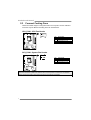
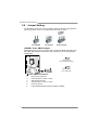
2.5 Expansion Slots
Install an Expansion Card
You can install your expansion card by following steps:
1. Read the related expansion card's instruction document before install the
expansion card into the computer.
2. Remove your computer's chassis cover, screws and slot bracket from the
computer.
3. Place a card in the expansion slot and press down on the card until it is
completely seated in the slot.
4. Secure the card’s metal bracket to the chassis back panel with a screw.
5. Replace your computer's chassis cover.
6. Power on the computer, if necessary, change BIOS settings for the
expansion card.
7. Install related driver for the expansion card.

H81MG
11
PEX16_1: PCI-Express Gen2 x16 Slot
- PCI-Express 2.0 compliant.
- Maximum theoretical realized bandwidth of 8GB/s simultaneously per
direction, for an aggregate of 16GB/s totally.
PEX1_1/1_2: PCI-Express Gen2 x1 Slots
- PCI-Express 2.0 compliant.
- Data transfer bandwidth up to 500MB/s per direction; 1GB/s in total

Motherboard Manual
12
2.6 Jumper Setting
The illustration shows how to set up jumpers. When the jumper cap is placed on
pins, the jumper is “close”, if not, that means the jumper is “open”.
Pin opened Pin closed Pin1-2 closed
JCMOS1: Clear CMOS Jumper
Placing the jumper on pin2-3, it allows user to restore the BIOS safe setting and
the CMOS data. Please carefully follow the procedures to avoid damaging the
motherboard.
31
Pin 1-2 Close:
Normal Operation (default).
31
Pin 2-3 Close:
Clear CMOS data.
※ Clear CMOS Procedures:
1. Remove AC power line.
2. Set the jumper to “Pin 2-3 close”.
3. Wait for five seconds.
4. Set the jumper to “Pin 1-2 close”.
5. Power on the AC.
6. Load Optimal Defaults and save settings in CMOS.

H81MG
13
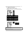
2.7 Headers & Connectors
ATXPWR1: ATX Power Source Connector
For better compatibility, we recommend to use a standard ATX 24-pin power
supply for this connector. Make sure to find the correct orientation before plugging
the connector.
Pin Assignment Pin Assignment
13 +3.3V 1 +3.3V
14 -12V 2 +3.3V
15 Ground 3 Ground
16 PS_ON 4 +5V
17 Ground 5 Ground
18 Ground 6 +5V
19 Ground 7 Ground
20 NC 8 PW_OK
21 +5V 9 Standby Voltage+5V
22 +5V 10 +12V
23 +5V 11 +12V
24 Ground 12 +3.3V
ATXPWR2: ATX Power Source Connector
The connector provides +12V to the CPU power circuit.
Pin Assignment
1 +12V
2 +12V
3 Ground
4 Ground
Note1: Before you power on the system, please make sure that both ATXPWR1 and ATXPWR2
connectors have been plugged-in.
Note2: Insufficient power supplied to the system may result in instability or the peripherals not
functioning properly. Use of a PSU with a higher power output is recommended when configuring a
system with more power-consuming devices.

Motherboard Manual
14
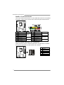
PANEL1: Front Panel Header
This 16-pin header includes Power-on, Reset, HDD LED, Power LED, and speaker
connection. It allows user to connect the PC case’s front panel switch functions.
Pin Assignment Function Pin Assignment Function
1 +5V 9 N/A
2 N/A 10 N/A
N/A
3 N/A 11 N/A N/A
4 Speaker
Speaker
Connector
12 Power LED (+)
5 HDD LED (+) 13 Power LED (+)
6 HDD LED (-)
Hard drive
LED
14 Power LED (-)
Power LED
7 Ground 15 Power button
8 Reset control
Reset button
16 Ground
Power-on button
SATA1~SATA2: Serial ATA 3.0 Connectors
These connectors connect to SATA hard disk drives via SATA cables. It satisfies
the SATA 3.0 specification and with transfer rate of 6.0Gb/s.
Pin Assignment
1 Ground
2 TX+
3 TX-
4 Ground
5 RX-
6 RX+
7 Ground

H81MG
15
SATA3~SATA4: Serial ATA 2.0 Connectors
These connectors connect to SATA hard disk drives via SATA cables. It satisfies
the SATA 2.0 specification and with transfer rate of 3.0Gb/s.
Pin Assignment
1 Ground
2 TX+
3 TX-
4 Ground
5 RX-
6 RX+
7 Ground
F_USB1/2: Header for USB 2.0 Ports at Front Panel
This header allows user to add additional USB ports on the PC front panel, and
also can be connected with a wide range of external peripherals.
Pin Assignment
1 +5V (fused)
2 +5V (fused)
3 USB-
4 USB-
5 USB+
6 USB+
7 Ground
8 Ground
9 NC
10 Key
J_COM: Serial Port Header
The motherboard has a serial port header for connecting RS-232 Port.
Pin Assignment
1 Carrier detect
2 Received data
3 Transmitted data
4 Data terminal ready
5 Signal ground
6 Data set ready
7 Request to send
8 Clear to send
9 Ring indicator
10 NC

Motherboard Manual
16
F_AUDIO1: Front Panel Audio Header
This header allows user to connect the chassis-mount front panel audio I/O which
supports HD and AC’97 audio standards.
HD Audio AC’97
Pin Assignment Pin Assignment
1 Mic Left in 1 Mic In
2 Ground 2 Ground
3 Mic Right in 3 Mic Power
4 GPIO 4 Audio Power
5 Right line in 5 RT Line Out
6 Jack Sense 6 RT Line Out
7 Front Sense 7 Reserved
8 Key 8 Key
9 Left line in 9 LFT Line Out
10 Jack Sense 10 LFT Line Out
Note1: It is recommended that you connect a high-definition front panel audio module to this
connector to avail of the motherboard's high definition audio capability.
Note2: Please try to disable the "Front Panel Jack Detection" if you want to use an AC'97 front
audio output cable. The function can be found via O.S. Audio Utility.
Note3: To configure 7.1-channel audio, you have to use a chassis with HD front panel audio
module and enable the multi-channel audio feature through O.S. Audio Utility.
JSPDIFOUT1: Digital Audio-out Connector
The connector is for connecting the S/PDIF output bracket.
Pin Assignment
1 +5V
2 SPDIF_OUT
3 Ground

H81MG
17
J_PRINT1: Printer Port Header
This header allows user to connect a printer to the PC.
Pin Assignment Pin Assignment
1 -Strobe 14 Ground
2 -ALF 15 Data 6
3 Data 0 16 Ground
4 -Error 17 Data 7
5 Data 1 18 Ground
6 -Init 19 -ACK
7 Data 2 20 Ground
8 -Scltin 21 Busy
9 Data 3 22 Ground
10 Ground 23 PE
11 Data 4 24 Ground
12 Ground 25 SCLT
13 Data 5 26 Key

Motherboard Manual
18
CHAPTER 3: UEFI BIOS & SOFTWARE
3.1 UEFI BIOS Setup
z The BIOS Setup program can be used to view and change the BIOS
settings for the computer. The BIOS Setup program is accessed by pressing
the <DEL> key after the Power-On Self-Test (POST) memory test begins
and before the operating system boot begins.
z For further information of setting up the UEFI BIOS, please refer to the UEFI
BIOS Manual in the Setup DVD.
3.2 BIOS Update
The BIOS can be updated using either of the following utilities:
z BIOSTAR BIOS Flasher: Using this utility, the BIOS can be updated from a
file on a hard disk, a USB drive (a flash drive or a USB hard drive), or a
CD-ROM.
z BIOSTAR BIOS Update Utility: It enables automated updating while in the
Windows environment. Using this utility, the BIOS can be updated from a file
on a hard disk, a USB drive (a flash drive or a USB hard drive), or a
CD-ROM, or from the file location on the Web.
BIOSTAR BIOS Flasher
BIOSTAR BIOS Flasher is a BIOS flashing utility providing you an easy and simple
way to update your BIOS via USB pen drive.
Note1: This utility only allows storage device with FAT32/16 format and single partition.
Note2: Shutting down or resetting the system while updating the BIOS will lead to system boot
failure.
Updating BIOS with BIOSTAR BIOS Flasher
1. Go to the website to download the latest BIOS file for the motherboard.
2. Then, copy and save the BIOS file into a USB flash (pen) drive.
3. Insert the USB pen drive that contains the BIOS file to the USB port.
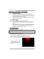
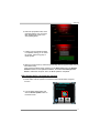
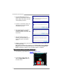
4. Power on or reset the computer and then press <F12> during the POST process.
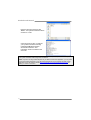
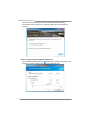
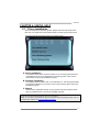
5. After entering the POST screen,
the BIOS-FLASHER utility pops
out. Choose [fs0] to search for the
BIOS file.
Page is loading ...
Page is loading ...
Page is loading ...
Page is loading ...
Page is loading ...
Page is loading ...
Page is loading ...
Page is loading ...
Page is loading ...
Page is loading ...
Page is loading ...
Page is loading ...
Page is loading ...
Page is loading ...
Page is loading ...
Page is loading ...
Page is loading ...
Page is loading ...
Page is loading ...
Page is loading ...
Page is loading ...
Page is loading ...
-
 1
1
-
 2
2
-
 3
3
-
 4
4
-
 5
5
-
 6
6
-
 7
7
-
 8
8
-
 9
9
-
 10
10
-
 11
11
-
 12
12
-
 13
13
-
 14
14
-
 15
15
-
 16
16
-
 17
17
-
 18
18
-
 19
19
-
 20
20
-
 21
21
-
 22
22
-
 23
23
-
 24
24
-
 25
25
-
 26
26
-
 27
27
-
 28
28
-
 29
29
-
 30
30
-
 31
31
-
 32
32
-
 33
33
-
 34
34
-
 35
35
-
 36
36
-
 37
37
-
 38
38
-
 39
39
-
 40
40
-
 41
41
-
 42
42


Ask a question and I''ll find the answer in the document
Finding information in a document is now easier with AI
Related papers
-
Biostar H81MHP Ver. 6.x User manual
-
Biostar H81MLC Ver. 7.x User manual
-
-
Biostar HI-FI Z87X 3D User manual
-
Biostar Hi-Fi Z87W Ver. 5.x User manual
-
-
-
-
-
Other documents
-
MSI H81I User manual
-
-
 Colorful C.H81A-BTC V20 User manual
-
Kingwin KW525-3U3CR User manual
-
Shuttle SH97R6 User manual
-
-
Shuttle SZ87R6 User manual
-
AG Neovo Keyboard & Mouse User manual
-
Foxconn G33M Quick Install Manual
-
NEC SigmaBlade B120a-D Installation guide
