Use of Trademarks, Registered Trademarks, and other Protected Names and Symbols
This manual may make reference to trademarks, registered trademarks, and other protected names and/or symbols of third-
party companies not related in any way to StarTech.com. Where they occur these references are for illustrative purposes only
and do not represent an endorsement of a product or service by StarTech.com, or an endorsement of the product(s) to which
this manual applies by the third-party company in question. StarTech.com hereby acknowledges that all trademarks, registered
trademarks, service marks, and other protected names and/or symbols contained in this manual and related documents are the
property of their respective holders.
Warranty Information
This product is backed by a 2-year warranty.
For further information on product warranty terms and conditions, please refer to www.startech.com/warranty.
Limitation of Liability
In no event shall the liability of StarTech.com Ltd. and StarTech.com USA LLP (or their ocers, directors, employees or agents)
for any damages (whether direct or indirect, special, punitive, incidental, consequential, or otherwise), loss of prots, loss of
business, or any pecuniary loss, arising out of or related to the use of the product exceed the actual price paid for the product.
Some states do not allow the exclusion or limitation of incidental or consequential damages. If such laws apply, the limitations
or exclusions contained in this statement may not apply to you.
FR: startech.com/fr
DE: startech.com/de
ES: startech.com/es
NL: startech.com/nl
IT: startech.com/it
JP: startech.com/jp
StarTech.com
Ltd.
45 Artisans Cres
London, Ontario
N5V 5E9
Canada
StarTech.com Ltd.
Unit B, Pinnacle 15
Gowerton Rd,
Brackmills
Northampton
NN4 7BW
United Kingdom
StarTech.com LLP
4490 South Hamilton
Road
Groveport, Ohio
43125
U.S.A.
StarTech.com Ltd.
Siriusdreef 17-27
2132 WT Hoofddorp
The Netherlands
Regulatory Compliance
FCC - Part 15
This equipment has been tested and found to comply with the limits for a Class B digital device, pursuant to part 15 of the FCC
Rules. These limits are designed to provide reasonable protection against harmful interference in a residential installation.
This equipment generates, uses and can radiate radio frequency energy and, if not installed and used in accordance with the
instructions, may cause harmful interference to radio communications. However, there is no guarantee that interference will not
occur in a particular installation. If this equipment does cause harmful interference to radio or television reception, which can be
determined by turning the equipment o and on, the user is encouraged to try to correct the interference by one or more of the
following measures:
• Connect the equipment into an outlet on a circuit dierent from that to which the receiver is connected.
• Consult the dealer or an experienced radio/TV technician for help
This device complies with part 15 of the FCC Rules. Operation is subject to the following two conditions:
(1) This device may not cause harmful interference, and (2) this device must accept any interference received, including
interference that may cause undesired operation. Changes or modications not expressly approved by StarTech.com could void
the user’s authority to operate the equipment.
Industry Canada Statement
This Class B digital apparatus complies with Canadian ICES-003.
Cet appareil numérique de la classe [B] est conforme à la norme NMB-003 du Canada.
CAN ICES-3 (B)/NMB-3(B)
This device complies with Industry Canada licence-exempt RSS standard(s). Operation is subject to the following two conditions:
(1) This device may not cause interference, and (2) This device must accept any interference, including interference that may
cause undesired operation of the device.
Le présent appareil est conforme aux CNR d’Industrie Canada applicables aux appareils radio exempts de licence. L’exploitation
est autorisée aux deux conditions suivantes:
(1) l’appareil ne doit pas produire de brouillage, et (2) l’utilisateur de l’appareil doit accepter tout brouillage radioélectrique subi,
même si le brouillage est susceptible d’en compromettre le fonctionnement.
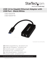
Note: Ensure the polarity of the power input is correctly matched with the DC 2-Wire
Terminal Block Pins to function properly and to prevent damage to the USB Hub and
any connected peripherals.
Terminal Block Pins
4. Insert the Terminal Block Connector Housing back into USB Hub.
Power the Hub Using an External Power Adapter
• Connect a Power Adapter (not included) to the Power Input Port, located on the
front of the USB Hub and to an AC Electrical Outlet.
DIN Rail Mounting
Connect the USB Ports
1. Connect up to 16 USB peripherals to the Screw Locking USB Data/Charge Ports,
located on the USB Hub.
2. Use the 2x USB-A to USB-B Cables (1x cable included, second sold separately), to
connect a USB port on each Computer to the USB Host A & B Ports, located on the
USB Hub.
• The Computer will automatically detect the device and install the required drivers
for the USB Hub.
Power the Hub
Power the Hub Using the 2-Wire Terminal Block
1. Remove the Terminal Block Connector Housing from the USB Hub’s Casing.
2. Loosen the screws for the Terminals located on the Terminal Block Connector,
using a Flat Head Screwdriver.
3. Connect the Positive and Negative Wires from the 12-24V DC Power Source (not
included) to the Terminals on the Terminal Block Connector.
V- (GND)
V+ (12~24V)
Requirements
• Computer (1 or 2 units)
• USB-A Port
• 12-24V DC Power Source
For the latest drivers, manuals, product information, technical specications, and
declarations of conformance, please visit: www.StarTech.com/5G16AINDS-USB-A-HUB
Installation
Notes:
• Connect the Power Source after all the other installation steps have been completed.
• There are two ways to power the USB Hub.
Using an external DC Power Adapter or a Terminal Block Power Source. Voltage
(+12 - 24 V DC).
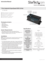
This USB Hub includes DIN Rail Brackets that can be used
to horizontally mount the USB Hub to a DIN Rail. To install
the DIN Rail Brackets on the USB Hub:
1. Align the Din Rail Brackets (x 2) with the DIN Rail
Mounting Holes, located on either side at the back of
the USB Hub.
2. Insert the Mounting Screws (x 4) through the DIN Rail
Brackets, and into the USB Hub.
3. Using a Phillips Head Screwdriver tighten the Mounting
Screws. Be careful not to over-tighten the Mounting
Screws.