Osram T4T-C 4DIM NFC Installation guide

Type
Installation guide
www.inventronicsglobal.com
Technical application guide
4DIM NFC G3 CE LED drivers
and T4T-C
05/2023
DALI-2StepDIM AstroDIM MainsDIM
Presence Constant
Lumen
Ext. NTC Surge
6/10 kV
Dif
Com
Data
Energy
Diagnostic
Tuning
Factor
Configuration
Lock
Driver Guard
T, P
Luminaire
Data
LEDset
4DIM NFC G3 CE LED drivers and T4T-C | Contents
2
Contents
1 Introduction 03
1.1 OSRAM LED drivers with 4DIM functionality
for outdoor and industrial applications 03
1.2 4DIM NFC product family 04
1.3 Nomenclature 07
1.4 Operating windows 07
1.4.1 Current foldback 08
1.4.2 Low input voltage protection 08
2 Features 09
2.1 Operating current 09
2.1.1 Fixed current mode 09
2.1.2 LEDset2 mode 09
2.1.3 Tuning Factor 11
2.2 Thermal derating and protection 11
2.2.1 External temperature sensor 11
2.2.2 Thermal management and Driver Guard feature 12
2.3 Constant Lumen function 13
2.4 Lamp operating time 13
2.5 End of life 13
2.6 Configuration Lock 15
3 Operating modes 16
3.1 On/off operating mode 16
3.2 AstroDIM feature 17
3.2.1 Wiring and feature activation 17
3.2.2 Time-based mode 18
3.2.3 Astro-based mode 19
3.2.4 Presence detection in AstroDIM mode 22
3.2.5 AstroDIM SD-triggered 23
3.3 StepDIM feature 24
3.3.1 StepDIM 25
3.3.2 StepDIM inverse 26
3.3.3 Autodetect, ON/OFF-StepDIM inverse 26
3.3.4 Autodetect, AstroDIM-StepDIM inverse 27
3.4 MainsDIM feature 28
3.5 DALI operating mode 29
3.5.1 DALI-2 30
3.5.2 Additional functions 30
3.6 DC operation feature 31
4 Additional information 32
4.1 Insulation 32
4.2 Cable preparation 32
4.3 Incorrect wiring on the output side 33
4.4 Input overvoltage 33
4.5 Surge protection 33
5 Programming 34
5.1 Programming with DALI magic 34
5.2 Programming with NFC USB readers 34
5.3 Programming with T4T-Field App 34
6 Additional information for electrical design-in 35
6.1 Recommended EMI wiring setup 35
6.2 Remote LED driver installation for Class I configuration 35
6.3 Remote LED driver installation for Class II configuration 35
Please note:
All information in this guide has been prepared with great
care. INVENTRONICS, however, does not accept liability
for pos sible errors, changes and/or omissions. Please check
www.inventronics-light.com or contact your sales partner
for an updated copy of this guide. This technical application
guide is for information purposes only and aims to support
you in tackling the challenges and taking full advantage of
all opportunities the technology has to offer. Please note that
this guide is based on own measurements, tests, specific
parameters and assumptions. Individual applications may not
be covered and need different handling. Responsibility and
testing obligations remain with the luminaire manu facturer/
OEM/application planner.
4DIM NFC G3 CE LED drivers and T4T-C | Introduction
3
1 Introduction
1.1 OSRAM LED drivers with 4DIM functionality
for outdoor and industrial applications
Long lifetime, low maintenance costs and high efficiency
are very important for outdoor and industrial applications.
OPTOTRONIC® LED drivers for outdoor applications meet
these requirements and unlock the full potential of LED-
based light sources.
Thanks to the high flexibility of the programmable
OPTOTRONIC® 4DIM NFC G3 CE LED drivers, LED lumi-
naire systems can be optimized to the on-site conditions
and cost. With the four integrated dimming functions
(4DIM), significant energy saving and a reduction of green-
house gas emissions can be achieved.
The NFC interface implemented in the 4DIM NFC G3 CE
family enables an easy and safe way of programming LED
drivers during the production process and also in the field.
The parameters can be transferred without the need to
power the LED driver, which saves time compared to a pro-
gramming process using the DALI-2 interface.
Due to the large operating window (voltage/current) of these
LED drivers, both OSRAM LED modules for outdoor appli-
cations and customer-specific LED modules can be operated.
This also means that the overall amount of different LED
drivers on stock can be kept low and that the overall com-
plexity of luminaire maintenance over the entire life cycle
can be reduced.
The drivers are DALI-2-certified and support stepless dimming,
status requests, and addressing of each individual light point.
Compared to devices based on DALI version 1, DALI-2-
certified drivers ensure a higher interoperability in the system.
Moreover, DALI-2 ensures better integration of additional
valuable data services thanks to the DALI DATA extensions
part -251 (Luminaire Info), part -252 (Energy Reporting) and
part -253 (Diagnostic Data).
With the LEDset2 interface, we have created a new path
towards standardizing the communication between the
LED driver and the LED modules. Without reprogramming,
LEDset2 ensures optimal efficiency, a high level of reliability
and the adaptability of the LED drivers to the latest LED
technologies.
Finally, due to integrated overvoltage protection, LED
drivers with 4DIM functionality provide a high level of
protection against common mode surges of up to 10 kV
forclass I and II luminaires.
4DIM NFC G3 CE LED drivers and T4T-C | Introduction
4
1.2 4 DIM NFC G3 CE product family
The 4DIM NFC G3 CE product family consists of six different out-
put power classes of up to 200 W. The new family consists of ten
different types, including variants with a higher output voltage
range to enable more and optimized luminaire concepts. All types
Table 1: Family overview
Product name OT 20/170-240/1A0
4DIM NFC G3 CE
OT 40/170-240/0A7
4DIM NFC G3 CE
OT 40/170-240/1A0
4DIM NFC G3 CE
OT 75/170-240/0A7
4DIM NFC G3 CE
OT 75/170-240/1A0
4DIM NFC G3 CE
OT 75/170-240/1A5
4DIM NFC G3 CE
General
Maximum power
22 W 40 W 40 W 75 W 75 W 75 W
Input voltage L/N
220 –240 V 220 –240 V 220 –240 V 220 –240 V 220 –240 V 220 –240 V
Nominal output voltage
10 –38 V 30 -77 V 15 –56 V 50150 V 35 –115 V 25–75V
Output current range
1050 mA 700 mA 1050 mA 700 mA 105 0 mA 1500 m A
Surge (dif/com)
6/10 kV 6/10 kV 6/10 kV 6/10 kV 6/10 kV 6/10 kV
DA-DA Surge
1 kV 1 kV 1 kV 1 kV 1 kV 1 kV
DALI-PE
8 kV 8 kV 8 kV 8 kV 8 kV 8 kV
Insulation
(primary/secondary)
SELV SELV SELV Double SELV SELV
Insulation of casing
Double Double Double Double Double Double
Stand-by power < 0.5 W < 0.5 W < 0.5 W < 0.5 W < 0.5 W < 0.5 W
have the same 4DIM dimming capabilities and the LEDset2
interface. They can be programmed via the Tuner4TRONIC®
software using the DALI-2 or NFC interface. The following
overview shows the main featuresof these LED drivers.
Table 2: Family overview
Product name OT 110/170-240/0A7
4DIM NFC G3 CE
OT 110/170-240/1A0
4DIM NFC G3 CE
OT 165/170-40/1A0
4DIM NFC G3 CE
OT 200/170-40/1A0
4DIM NFC G3 CE
General
Maximum power
110 W 110 W 165 W 200 W
Input voltage L/N
220 –240 V 220 –240 V 220 –240 V 220 –240 V
Nominal
output voltage
80 –220 V 55 –157 V 90 –260 V 140–300 V
Output
current range
700 mA 1050 mA 1050 mA 15 00 mA
Surge (dif/com)
6/10 kV 6/10 kV 6/10 kV 6/10 kV
DA-DA Surge
1 kV 1 kV 1 kV 1 kV
DALI-PE
8 kV 8 kV 8 kV 8 kV
Insulation
(primary/secondary)
Double Double Double Double
Insulation of casing
Double Double Double Double
Stand-by power < 0.5 W < 0.5 W < 0.5 W < 0.5 W
4DIM NFC G3 CE LED drivers and T4T-C | Introduction
5
Features
All types offer the same functionalities and feature-set.
DALI-2 StepDIM (SD(2)) StepDIM inverse
(SD(2))
AstroDIM
(astro-based)
AstroDIM
(time-based)
MainsDIM Presence detection
DALI-2StepDIM StepDIM AstroDIM AstroDIM MainsDIM Presence
Other features
Constant
Lumen function
DALI-2 DATA LEDset2 External NTC Configuration Lock Tuning Factor Driver Guard T, P
Programming software
Tuner4TRONIC®
Constant
Lumen
Luminaire
Data
Data
Energy
Diagnostic
LEDset Ext. NTC
Configuration
Lock
Tuning
Factor
Driver Guard
T, P
It is possible to operate the driver below the minimum nominal current through initial setting of the output current.
Warning:
When LED drivers are permanently operated below the minimum nominal current, it is necessary to ensure compliance
with relevant IEC standards (for example mains current distortion and power factor). Please consider that the certificates
are only valid within the nominal output current range.
DALI-2
DALI-2
In this operating mode, the driver can be controlled by a
DALI application controller via the bidirectional DALI inter-
face and it supports status request queries. Through the
application controller, the driver can be integrated into a
light management system.
The drivers are DALI-2-certified and support stepless dim-
ming, status requests, and addressing of each individual
light point. Compared to devices based on DALI version 1,
DALI-2-certified drivers ensure more functions and a higher
interoperability in the system.
StepDIM/StepDIM inverse
StepDIM
Dimming via an external control phase: Predefined dimming
levels can be varied via the Tuner4TRONIC® software and
the polarity of the phase. The SD2 port also allows control
via a mains-powered presence sensor.
AstroDIM/presence detection
AstroDIM
Presence
Automatic dimming via an integrated timer (no real-time
clock): Five independent dimming levels and zones can be
set with the Tuner4TRONIC® software. Brightness variation
is possible in combination with an external presence sensor.
MainsDIM
Dimming via mains voltage amplitude: This feature is often
used in combination with magnetic ballasts in outdoor
applications. The dimming behavior can be set via the
Tuner4TRONIC® software.
MainsDIM
CLO (constant lumen output)
Constant
Lumen
The decrease in the luminous flux of an LED module can be
compensated over its entire lifetime via a preprogrammed
current curve. This not only ensures stable lighting but also
saves energy and increases the lifetime of the LEDs.
Monitoring Data
Luminaire
Data
Data
Energy
Diagnostic
LED drivers with this feature offer additional operation and
status information according to the DALI-2 DATA extensions
(Parts -251, -252 and -253) such as energy consumption,
power, operating time, overvoltage or undervoltage etc.
Byusing these data, it is possible to offer predictive main-
tenance and an overall better lighting service. Moreover, it
makes the light management system intelligent.
The data can also be visualized in the Tuner4TRONIC® soft-
ware.
4DIM NFC G3 CE LED drivers and T4T-C | Introduction
6
LEDset
LEDset
LEDset is an improved LED module interface for the
combination of single or multiple LED modules with one
LED driver via a single analog control line. This interface
enables external current setting and temperature monitoring.
The LEDset2 interface has no auxiliary supply and is not
compatible with LEDset (Generation 1). LEDset2 has an
absolute current coding, while LEDset (Generation 1) only
has a relative one. In the 4DIM NFC G3, LEDset and NTC
functionality share the same connection terminal. Both fea-
tures are not simultaneously available.
LEDset functionalities are limited only to the current setting
(via codified resistor) and to thermal protection via PTC
(5 V supply, miswiring protection, thermal protection
with NTC are not available).
External temperature sensor
Ext. NTC
This feature allows the temperature protection of the LED
module or the complete luminaire in hot ambient tempera-
tures via an external sensor (e.g. NTC, negative tempera-
ture coefcient resistor). The derating can be modified via
the Tuner4TRONIC® software.
Integrated overvoltage protection
Surge
6/10 kV
Dif
Com
EQUI
The 4DIM CE drivers have an integrated overvoltage pro-
tection of up to 6 kV for differential and 10 kV for common-
mode overvoltages.
Configuration Lock
Configuration
Lock
This feature is an advancement of OEM Key, which allows
controlling the access rights for individual features within
the LED driver via Tuner4TRONIC® software and assigning
different rights to the luminaire manufacturer, to the service
team and to the general user. Assigning user rights also
allows offering “light as a service” and still maintaining total
control over who may change what within the device or lu-
minaire.
Tuning Factor
Tuning
Factor
Within limits predefined by the luminaire manufacturer,
this feature allows an adjustment of the amount of light in
the field or in production. Thus, one luminaire can manage
different lumen packages. If the feature is combined with
LEDset, other lumen packages can also be achieved,
which differ in terms of resistor coding.
Driver Guard T, P
Driver Guard
T, P
By default, the internal protection mechanisms of the LED
driver are designed for maximum performance and tempera-
ture, however, not for those of the luminaire. By means of
this feature, the performance and temperature derating of
theLED driver can be adjusted according to the luminaire
performance, maximizing the system reliability.
4DIM NFC G3 CE LED drivers and T4T-C | Introduction
7
1.3 Nomenclature
The product name of each OPTOTRONIC® 4DIM CE LED
driver is defined as shown below.
1.4 Operating windows
The OPTOTRONIC® 4DIM NFC G3 CE LED driver family is
split up into six different power classes to provide the best
suitable power supply for different applications. The nominal
output current of 150-1050 mA (1500 mA for 1 version) is
available in the following power packages.
Figure 2 gives a complete overview of the possible
4DIM NFC G3 operating windows.
OT: OPTOTRONIC® LED driver
40: Power class: 40 W
170-240: Input voltage range (L/N): 170-240 V
1A0: Max. output current: 1050 mA
4DIM: 4DIM functionality (DALI, StepDIM,
AstroDIM, MainsDIM)
NFC: NFC for LED driver programming
G2: Generation 2
C: Compact housing shape
E: For exterior use under specific conditions
Figure 1: OT 40/170-240/4DIM NFC G3 CE
Figure 2: Overview of 4DIM NFC G3 CE operating
windows
Output voltage [V] Nominal range Dimming range
Output current [A]
0
100
260
300
100 200 300 400 500 600 700 800 900
1000 1100 1200
20
40
60
80
120
140
160
180
200
220
240
280
Output voltage [V] Nominal range Dimming range
Output current [A]
100
0
20
100
120
140
40
60
80
200 300 400 500 600 700 800 900
1000 1100 1200 1300 1400 1500
OT 110/170-240/1A0 4DIM NFC G3 CE
OT 200/170-240/1A0 4DIM NFC G3 CE
OT 165/170-240/1A0 4DIM NFC G3 CE
OT 110/170-240/0A7 4DIM NFC G3 CE
OT 20/170-240/1A0 4DIM NFC G3 CE
OT 75/170-240/1A0 4DIM NFC G3 CE
OT 40/170-240/1A0 4DIM NFC G3 CE
OT 40/170-240/0A7 4DIM NFC G3 CE
OT 75/170-240/1A5 4DIM NFC G3 CE
OT 75/170-240/0A7 4DIM NFC G3 CE
4DIM NFC G3 CE LED drivers and T4T-C | Introduction
8
It is possible to operate the driver below the minimum nominal current through initial setting of the output current.
Warning:
When LED drivers are permanently operated below the minimum nominal current, it is necessary to ensure compliance
with relevant IEC standards (for example mains current distortion and power factor). Please consider that the certificates
are only valid within the nominal output current range.
Table 3: 4DIM NFC G3 CE operating range
Type OT 20/170-
240/1A0 4DIM
NFC G3 CE
OT 40/170-
240/0A7 4DIM
NFC G3 CE
OT 40/170-
240/1A0 4DIM
NFC G3 CE
OT 75/170-
240/0A7 4DIM
NFC G3 CE
OT 75/170-
240/1A0 4DIM
NFC G3 CE
OT 75/170-
240/1A5 4DIM
NFC G3 CE
OT 110/170-
240/0A7 4DIM
NFC G3 CE
OT 110/170-
240/1A0 4DIM
NFC G3 CE
OT 165/170-
240/1A0 4DIM
NFC G3 CE
OT 200/170-
240/1A0 4DIM
NFC G3 CE
Pmax 22 W 40 W 40 W 75W 75 W 1) 75W 110 W 110 W 1) 165 W 1) 200 W
ta
-40 ...+60 °C -40 ...+60 °C -40 ...+60 °C -4 0…+55 °C -40 ...+55 °C -40…+60 °C -4 0…+55 °C -40 ...+55 °C -40 ...+55 °C - 40…+5 5 °C
Vin
(nominal)
220–240 VAC 220240 VAC 220–240 VAC
220–240V
220–240 VAC
220–240V 220–240V
220–240 VAC 220240 VAC
220-240VAC
Minimum
dimming
current
70 mA 70 mA 70 mA 70 mA 70 mA 70 mA 70 mA 70 mA 70 mA 70 mA
Minimum
nominal
current
150 mA 150 mA 150 mA 150 mA 150 mA 350 mA 150 mA 150 mA 150 mA 150 mA
Maximum
nominal
current
1050 mA 700 mA 1050 mA 700 mA 1050 mA 1500 mA 700 mA 1050 mA 1050 mA 1050 mA
Minimum
output
voltage
10 V 30 V 15 V 50 V 35 V 25 V 80 V 55 V 90 V 140 V
Maximum
output
voltage
38 V 77 V 56 V 150 V 115 V 75 V 220 V 157 V 260 V 300 V
1) At input voltages below 190 V, the driver protects itself as shown in figure 4.
4DIM NFC G3 CE LED drivers and T4T-C | Introduction
9
1.4.1 Current foldback
The intelligent 4DIM NFC G3 family allows a safe start-up
of the system, even if the power consumption or the total
forward voltage of the LED module exceeds the maximum
output power or voltage of the LED driver. In this case, the
unit reduces the current until the maximum output voltage
[1] or power [2] is not exceeded anymore. If no stable operating
point is achieved, the unit switches on and off continuously or
switches off completely.
1.4.2 Low input voltage protection
In case of a very low input voltage, the driver protects itself
against being damaged by high input currents. The behavior
of the driver can be seen in figure 4.
Figure 4: Input voltage vs. output power OT 40 4DIM
NFC G3 CE driver
A [%] = B [%] C [%]
OT 20/170-240/1A0
4DIM NFC G3 CE 40 40 75
OT 40/170-240/XXX
4DIM NFC G3 CE 68 68 85
OT 75/170-240/XXX
4DIM NFC G3 CE 70 70 85
OT 110/170-240/XXX
4DIM NFC G3 CE 70 70 85
OT 165/170-240/1A0
4DIM NFC G3 CE 50 50 75
OT 200/170-240/1A0
4DIM NFC G3 CE 50 50 75
Output power
Mains voltage
145 VAC
=
100 %
B[%]
C[%]
150 VAC 170 VAC
190 VAC
A[%]
Please note:
At ambient temperatures below -25 °C, the LED driver
supplies 200 mA for a maximum of 1 minute to warm up,
and after this, it supplies the programmed output current.
Figure 3: Current foldback (example: OT 40 4DIM
NFC G3 CE)
Output current [A]
Output voltage [V]
0.2 0.4 0.6 0.8 11.2
0
10
20
30
40
50
1
2
4DIM NFC G3 CE LED drivers and T4T-C | Features
10
LT2/NTC
SD(2)
N
L
LED-
LED-
LED+
DA
DA
LT2/NTC
SD(2)
N
L
LED-
LED-
LED+
DA
DA
2 Features
2.1 Operating current
Flexible current setting allows taking advantage of the
continuously improving LED technology and building a
future-proof system. The 4DIM NFC G3 family offers two
modes for current setting, which can be set via the
Tuner4TRONIC® software:
Fixed current: Current setting via programmable
interface
LEDset2: Current setting via the LEDset2 interface
Without any resistor connected to the LEDset2 interface,
the factory default current is 700 mA. As soon as the LED
driver detects a resistor value for more than 3 seconds
within the valid resistor range (see table 4), it switches to
the LEDset2 mode.
2.1.1 Fixed current mode
To use the fixed current mode, it has to be selected in the
Tuner4TRONIC® software. The minimum and maximum ra t-
ed output currents are displayed according to the selected
LED driver. The output current of the LED driver can be set
by changing the value in the “Operating Current” field.
2.1.2 LEDset2 mode
The LEDset2 interface (LEDset generation 2) is a stan dardized
LED module interface to set the right output current and es-
tablish an easy and low-cost temperature protection for the
connected LED module. This multi-vendor interface is suit-
able for LED modules connected in parallel or in series.
Note:
In the following figures, the LED module is displayed in a
simplified way. The real number of LEDs depends on the
output voltage of the driver.
Figure 6: LEDset2 parallel connection
Figure 7: LEDset2 series connection
Figure 5: Setting of the operating current
Luminaire 1
Rset Rset
4DIM NFC G3 CE
LED module LED module
Luminaire 1
Rset Rset
LED module LED module
4DIM NFC G3 CE
EQUI
EQUI
4DIM NFC G3 CE LED drivers and T4T-C | Features
11
LT2/NTC
SD(2)
N
L
LED-
LED-
LED+
DA
DA
LT2/NTC
SD(2)
N
L
LED-
LED-
LED+
DA
DA
The output current of the LED driver can be set using an
externally connected resistor (min. power rating 50 mW,
max. tolerance 0.5 %). This provides the possibility to set
the LED current manually without the need for an additional
programming of the LED driver. With a resistor mounted on
the LED module as shown in figure 8, the correct LED cur-
rent can be set automatically. With this resistor, the desired
current for the LED module is set according to the used
LED bin and needed lumen output, offering a real plug-
and-play solution and making the system future-proof.
The LEDset2 coding for the 4DIM NFC G3 family is shown
in the following graph.
For further details, please consult the LEDset2 application
guide, which can be downloaded at
https://www.inventronics-light.com/application-guides.
The corresponding output current can be calculated
with the following formula within the valid resistor range
(Rset = 4.7524.9 kΩ):
The undefined range should be avoided because the
output current of the LED driver is not predictable.
Table 4 gives an overview of commonly used current
values and the appropriate resistor values.
To achieve a more accurate current setting, the second
LED- terminal of the LED driver can be used as shown in
figure 9. This increases the accuracy by roughly 0.5 %.
Figure 8: Rset connection
Figure 10: LEDset2 coding
Figure 9: Rset connection with higher accuracy
Table 4: LEDset2 resistor coding
Iout [mA]
reference
Rset [kΩ]
[tolerance ≤ 0.5 %]
Iout [mA]
nominal
Open circuit > 71 70
150 33.3 150
200 24.9 201
350 14.3 (E192) 349
500 10.0 (E192) 500
700 7.14 (E192) 699
1050 4.75 (E192) 1050
1500 3.33 1502
Undefined 0.92.37 1050/70
Short circuit < 0.9 70
I
out [A] = 5 V x 1000
Rset [Ω]
Luminaire 1
Rset
LED module
4DIM NFC G3 CE
Luminaire 1
Rset
LED module
4DIM NFC G3 CE
EQUI
EQUI
Rset [kΩ]
Output current [mA]
110 100
0
200
400
600
800
1000
1
2
1 Undefined range 2 Nominal range
4DIM NFC G3 CE LED drivers and T4T-C | Features
12
LT2/NTC
SD(2)
N
L
LED-
LED-
LED+
DA
DA
2.2 Thermal derating and protection
2.2.1 External temperature sensor
By connecting an external temperature sensor to the
NTCset port of the 4DIM NFC G3 CE LED driver, a very
easy and cost-efficient temperature protection of the LED
module can be realized. As an example, an NTC (negative
temperature coefficient resistor) can be mounted on the
LED module and connected as shown in figure 12. In case
the thermal protection feature is enabled and nothing is
connected to the NTCset terminal, the driver delivers 100 %
light output.
Figure 12: NTC connection
2.1.3 Tuning Factor
Modern street lighting has a high energy saving potential as
efficient LED technology allows light planners and luminaire
manufacturers to perfectly adapt the behavior of the luminaire
to the requirements of the illuminated street. On the other
hand, this flexibility increases the complexity of maintaining
the installation for cities and installers.
Our Tuning Factor feature helps to reduce this complexity to
a minimum as it enables installers to adapt the settings of a
luminaire according to their current needs.
Example:
A luminaire manufacturer develops a luminaire which can
be operated within a range of 2,0004,000 lm. The installer
commissioned by the city can then use the Tuner4TRONIC®
Field application to adjust the lumen output via the NFC
programming interface to the level that is needed, while not
exceeding the limits set by the luminaire manufacturer.
Maximum limit:
This is the maximum operating current set by the luminaire
manufacturer. It is equivalent to 100 %.
Minimum limit:
This is the minimum definable output current level. Valid
range: 50100 %.
Luminaire reference light output:
This value indicates a reference light output of the luminaire
at 100 % output current. This enables the installer to easily
adjust the light output in lumen instead of the output current.
Tuning level:
This is the current tuning level set by the installer.
The “limits and reference lumen” can be independently pro-
tected by the Configuration Lock feature in order to avoid un-
authorized usage of this feature outside the limits defined by
the luminaire manufacturer.
Figure 11: Tuner4TRONIC® user interface: Tuning Factor
Luminaire 1
LED module
NTC
4DIM NFC G3 CE
EQUI
1) Switch-on temperature in case the temperature has reached the
shut-off condition
4DIM NFC G3 CE LED drivers and T4T-C | Features
13
Resistor-based mode
The resistor-based mode is activated by default. If the con-
nected resistor sensor value falls in the range between 6.3
and 5.0 kΩ, the output current is continuously lowered
down to 50 %. If the value falls further below 4.3 kΩ, the
output is switched off completely until the sensor reaches
5.0 kΩ again. The complete switch-off can be deactivated
by clicking on the “Shut Off” check box.
In this mode, a common NTC can be used to achieve a
fixed thermal protection as shown in table 5. The specified
temperatures can vary, depending on the used NTC com-
ponent and the corresponding tolerances.
Table 5: Overview of standard NTCs
NTC type Start derating
temperature
[6.3 kΩ]
End derating
temperature
1)
[5.0 kΩ]
Shut-off
temperature
[4.3 kΩ]
22 kΩ 56 °C 62 °C 67 °C
33 kΩ 66 °C 72 °C 77 °C
47 kΩ 75 °C 83 °C 87 °C
68 kΩ 85 °C 92 °C 97 °C
2.2.2 Thermal management and Driver Guard feature
The 4DIM NFC G3 CE LED driver family has a reversible
internal thermal protection. If the maximum allowed LED
driver temperature is exceeded, the LED driver starts derating
the output current down to 55 %. If the temperature keeps
increasing, the LED driver switches off. It switches back on
at the maximum allowed temperature.
In outdoor installations especially, the lifetime and reliability
of a luminaire is very important. As the lifetime of a luminaire
always depends on the operating temperature of the com-
ponents, the “Driver Guard” feature helps limiting the LED
driver’s temperature during its operation. The thermal behavior
of the LED driver can be activated at lower temperatures using
the “Prestart Derating” setting shown in the figure below.
Note:
The luminaire manufacturer is responsible for the proper
thermal design of the luminaire. The temperature indicated
in this feature might significantly differ from the tc tempera-
ture mentioned on the top of the LED driver. To achieve the
lifetime data of the LED driver, the luminaire manufacturer
needs to ensure that the maximum tc temperature is never
exceeded.
4DIM NFC G3 CE LED drivers and T4T-C | Features
14
2.3 Constant Lumen function
Over the lifetime of an LED module, the light output drops
due to the aging process of the LEDs. To achieve a con-
stant light output of the module, the LED driver stores the
operating hours of the LED module and increases the
output current to react to the light output drop. To set this
feature according to the applied LED module, the
Tuner4TRONIC® software can be used as shown, for
example, in figure 13.
The output levels have to be steadily increasing from the
beginning to the end.
The output level cannot fall below the minimum physical
dimming level of the LED driver, even if the software dis-
plays a lower value.
Next to the table, the estimated energy savings are calcu-
lated as shown in figure 13. This value is only an estimation
because it does not consider, for example, the LED Vf be-
havior and efficiency of the driver.
The exact values for programming the Constant Lumen
function for the connected LED module need to be obtained
from the corresponding LED or LED module supplier.
Actual lamp operating time can be displayed and edited
in the feature tab "Operating Time for ECGs without
Monitoring Data".
Lamp operating time allows the display and editing of the
actual on-time of the LED module, which is the basis for
theCLO (constant lumen output) profile. Drivers that feature
monitoring data (DiiA: DALI part -253) use “Light Source
Diagnostics and Maintenance: On Time – Resettable” to
display elapsed time for CLO. “On-Time – Resettable” can
be edited by reading Monitoring Data from drivers with
T4T-P4.
2.4 Lamp operating time
The LED driver monitors the operating hours of the con-
nected LED module. In case of a fault of the LED driver or
module, the lamp operating time has to be (re)set accord-
ingly with the Tuner4TRONIC® software. The lamp operat-
ing time also has an influence on the constant lumen func-
tion and the “end of life” feature. It can be set using the
Tuner4TRONIC® software as shown in figure 14.
2.5 End of life
The LED driver can indicate that a preprogrammed lifetime
of the connected LED module is reached and the module
should be replaced. This function has to be activated in
advance via the Tuner4TRONIC® software. The “end of life”
indication can be programmed as shown in figure 15.
If the specified lifetime is reached, the LED driver indicates
this through a lower light output during the first 10 minutes
of the switch-on period as shown in figure 16.
Figure 14: Lamp operating time (10 kh)
Figure 15: “End of life” setting
Figure 13: Constant lumen programming graph (operating time = 10 kh)
4DIM NFC G3 CE LED drivers and T4T-C | Features
15
Figure 16: “End of life” behavior without switch-on
fade time
Figure 17: “End of life” behavior with long switch-on
fade time
Figure 18 : “End of life” behavior with short switch-
on fade time
If a switch-on fade time is set, it is overriden by the “end of
life” functionality as shown in figure 17. After 10 minutes,
the output current is set according to the current switch-on
fade time level.
Note:
In DC operation, the “end of life” indication is deactivated
until the next power-on/off cycle or DALI operation.
If the switch-on fade time is shorter than 10 minutes, the
output current is directly switched to the nominal output
level after the “end of life” indication as shown in figure 18.
Time Time
Time
Output level [%] Output level [%]
Output level [%]
Output
current
Output
current
Output
current
10 minutes “end
of life” indication
10 minutes “end
of life” indication
10 minutes “end
of life” indication
Switch-on
fade time
Switch-on
fade time
Minimum
dimming
current
Minimum
dimming
current
Minimum
dimming
current
4DIM NFC G3 CE LED drivers and T4T-C | Features
16
2.6 Configuration Lock
The protection of the LED driver settings is mandatory to
guarantee a safe operation of a luminaire over its entire life-
time. In order to meet growing market demands to change
settings of a luminaire in the field, we developed a new
Configuration Lock, allowing a safe operation of the luminaire
while also giving the end customers the possibility to adapt
the settings of the luminaire in the field. With this approach,
the luminaire manufacturer keeps the complete control on
the boundaries defining how his product will be operated.
Example 1:
Luminaire manufacturer locks all settings, no in-field
changes possible.
The luminaire manufacturer sets a “Master Key” and locks
all the features. Without knowing the programmed “Master
Key,” nobody can change the LED driver settings anymore.
Features can be kept unlocked by selecting “Everyone” in
the corresponding line.
Example 2:
Luminaire manufacturer defines boundary conditions and
enables in-field programming.
The luminaire manufacturer defines his “Master Key” and
keeps the full access rights to the settings of the LED driv-
er. An additional “Service Key” can be set to allow people
knowing this key to adapt the corresponding feature(s) of
the LED driver.
In this example, people who received the “Service Key
(e.g. service personnel) can change the light output of the
luminaire using the tuning factor level. As the “Limits and
Reference Lumen” of the Tuning Factor feature is locked, the
user can only adapt the light output within the limits defined
by the luminaire manufacturer. In this case, all settings
related to operating modes and AstroDIM can be changed.
4DIM NFC G3 CE LED drivers and T4T-C | Operating modes
17
3 Operating modes
The operating modes of a 4DIM NFC G3 CE LED driver can
be selected using the Tuner4TRONIC® software. Only one
mode can be selected.
3.1 On/off operating mode
4DIM NFC G3 CE LED drivers can also be used in a simple
on/off operating mode. One of the following dimming
modes needs to be selected:
StepDIM/AstroDIM/DALI (wiring selection) – DALI and
SD(2) port not connected
StepDIM (DALI) – DALI and SD(2) port not connected
DALI – DALI port not connected
Note:
Be aware that the parameters set in these operating modes
also have an influence on the behavior of the LED driver in
the on/off operating mode.
Note:
DALI always has a higher priority than the selected operat-
ing mode and can be activated by a valid DALI command in
every mode. After a power-off/on cycle, the LED driver op-
erates in the originally selected dimming mode again.
The LED driver offers the possibility to select one of the
two dimming modes “StepDIM (DALI)” or “AstroDIM (DALI)
via external wiring in case the default dimming mode “Step-
DIM/AstroDIM/DALI (wiring selection)” is set. Please see
chapter 3.2.1 for wiring information.
Figure 19: Operating/dimming modes
Figure 20: Wiring for on/off operation
Luminaire 1 Luminaire 2
LT2 / NTC
SD(2)
N
L
LED-
LED-
LED+
DA
DA
LT2 / NTC
SD(2)
N
L
LED-
LED-
LED+
DA
DA
LED module
LED module
S1
4DIM NFC G3 CE
Switching cabinet
PE
L1
N
4DIM NFC G3 CE
EQUI
EQUI
4DIM NFC G3 CE LED drivers and T4T-C | Operating modes
18
3.2 AstroDIM feature
The AstroDIM feature allows an autonomous dimming without
the need for an additional control line. The 4DIM NFC G3
CE LED drivers support up to five independent dimming
levels and flexible settings of fade times between the
individual dimming levels.
The output levels can be set to 0 % (OFF) or between 10 %
and 100 % in steps of 1 %.
In addition, switch-on and switch-off fade times can be
programmed at the beginning and the end of a switching
cycle to allow for further energy savings during the twilight
phase. This function is also helpful for installations with a
pedestrian crossing where no specific infrastructure is
available to switch the pedestrian crossing illumination
independently of the rest of the street light illumination.
Two different modes for AstroDIM are supported:
Time-based: The dimming profile defined in the reference
schedule is referenced to the switch-on time of the LED
driver.
Astro-based: The dimming profile defined in the reference
schedule is referenced to the annual average middle of the
night, which is calculated based on the theoretical sunrise
and sunset times.
The LED driver does not have a real-time clock. The inter-
nal reference clock is derived from the mains frequency
and the driver detects if it is connected to a 50 Hz or 60 Hz
supply system, assuming a time base of 20 ms or 16.6 ms.
This allows a synchronized switching of all units. In case
of DC operation (see chapter 3.6), the dimming mode is
stopped until the AC voltage is applied again and a power-
off/on cycle is performed.
Warning:
If the output level is set below the minimum physical dimming
level of the LED driver (except OFF), the minimum dimming
current is used. The software still displays the original value.
If the output level falls below the minimum allowed dimming
current, the value is visualized in red.
3.2.1 Wiring and feature activation
There are two ways to activate the AstroDIM mode:
Option 1: By external wiring
Selected dimming mode (factory default):
“StepDIM/AstroDIM/DALI (wiring selection)”
Option 2: Via the Tuner4TRONIC® software
Selected dimming mode: “AstroDIM (DALI)” or
AstroDIM PD (DALI)”
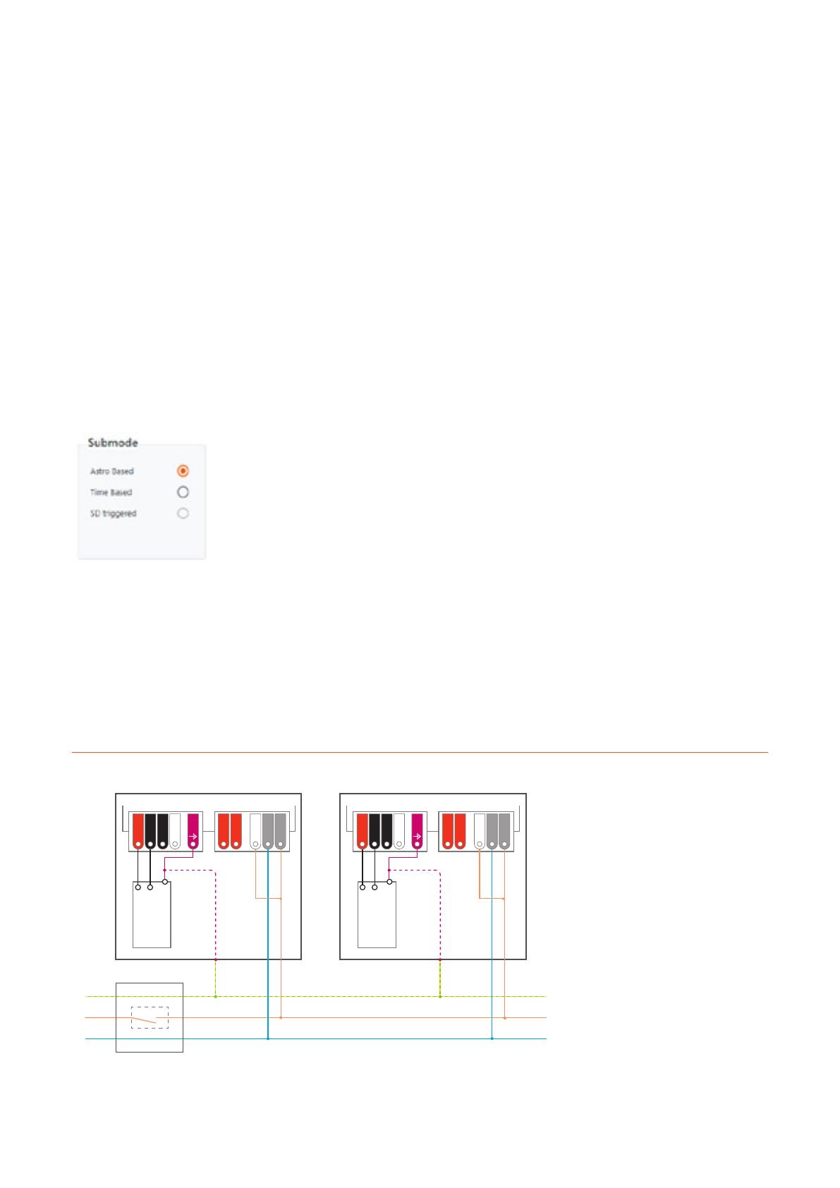
For option 1, the AstroDIM feature is activated without the
need for programming. Only a permanent connection between
the L and the SD(2) port of the LED driver is necessary (see
figure 21). If the SD(2) port is not active during the start-up
phase of the LED driver (for 1 s), the StepDIM feature is
activated instead of the AstroDIM feature. Information on
the default dimming profile can be found in the datasheet
of the applied LED driver.
For option 2, the external wiring can be avoided if either the
AstroDIM (DALI)” or “AstroDIM PD (DALI)” dimming mode is
selected via the software (see figure 22).
Figure 21: Wiring: StepDIM/AstroDIM/DALI (wiring selection)
LED module
LED module
S1
Luminaire 1
4DIM NFC G3 CE
Switching cabinet
PE
L1
N
Luminaire 2
4DIM NFC G3 CE
LT2 / NTC
LED-
DA
DA
LT2 / NTC
SD(2)
N
L
LED-
LED-
LED+
DA
DA
SD(2)
N
L
LED-
LED+
EQUI
EQUI
4DIM NFC G3 CE LED drivers and T4T-C | Operating modes
19
3.2.2 Time-based mode
In this mode, the LED driver performs the dimming profile
defined in the reference schedule based on the switch-on
time of the unit. Five independent output levels can be set
for each step. The minimum length of one dimming period
has to be longer than the AstroDIM fade time.
The maximum duration of the schedule is 23 h and 59 min.
Ifless than five output levels need to be performed, two
sequenced levels have to be set to the same value. The
AstroDIM dimming profile in the time-based mode already
starts after the first power-off/on cycle after programming.
Figure 22: Wiring: AstroDIM (DALI) or AstroDIM PD (DALI)
Figure 23: Time-based AstroDIM
Fade timing:
AstroDIM fade time: Fade time between the different
dimming levels.
Switch-on fade time: Fade time after the power-on
of the LED driver. The output level at the end of this fade
time is defined by the output level of the corresponding
dimming period.
Table 6: Fade timing parameters
(time-based mode)
Parameter Min. Max. Default
AstroDIM fade time 0, 2 s 8 min 3 min
Switch-on fade time 0, 15 s 60 min 0 s
LED module
LED module
S1
Luminaire 1
4DIM NFC G3 CE
Switching cabinet
PE
L1
N
Luminaire 2
4DIM NFC G3 CE
LT2 / NTC
SD(2)
LED-
LED-
DA
DA
LT2 / NTC
SD(2)
LED-
LED-
DA
DA
N
L
LED+
N
L
LED+
EQUI
EQUI
4DIM NFC G3 CE LED drivers and T4T-C | Operating modes
20
Fade timing:
AstroDIM fade time: Fade time between the different
dimming levels.
To achieve further energy savings in the twilight phase, the
switch-on and switch-off fade time can be set to up to 60
minutes.
Switch-on fade time: Fade time after the LED driver
has been powered on. The output level at the end of
this fade time is defined by the output level of the related
dimming period (step x).
Switch-off fade time: Fade time prior to the estimated
power-off point. The switch-off fading is performed
down to the minimum dimming current until the LED
driver is switched off externally.
Table 7: Fade timing parameters
(astro-based mode)
Parameter Min. Max. Default
AstroDIM fade time 0, 2 s 8 min 3 min
Switch-on fade time 0, 15 s 60 min 0 s
Switch-off fade time OFF, 0 s 60 min OFF
3.2.3 Astro-based mode
In this mode, the LED driver performs a dimming profile
based on the daily power-on and power-off times. The
dimming schedule is adapted according to the length of
the night.
The Tuner4TRONIC® software calculates the annual aver-
age middle of the night based on the theoretical sunrise
and sunset times, which are related to the location selected
in the software. Based on this average middle of the night,
five independent dimming periods can be defined in the
reference schedule. The minimum length of one dimming
period has to be longer than the AstroDIM fade time. Valid
time values can be set between 12:00 pm and 11:59 am.
Ifless than five output levels need to be performed, two
sequenced levels have to be set to the same value.
The defined dimming profile is already performed after the
second power-off/on cycle after programming.
Figure 24: Astro-based AstroDIM
  • Page 1 1
  • Page 2 2
  • Page 3 3
  • Page 4 4
  • Page 5 5
  • Page 6 6
  • Page 7 7
  • Page 8 8
  • Page 9 9
  • Page 10 10
  • Page 11 11
  • Page 12 12
  • Page 13 13
  • Page 14 14
  • Page 15 15
  • Page 16 16
  • Page 17 17
  • Page 18 18
  • Page 19 19
  • Page 20 20
  • Page 21 21
  • Page 22 22
  • Page 23 23
  • Page 24 24
  • Page 25 25
  • Page 26 26
  • Page 27 27
  • Page 28 28
  • Page 29 29
  • Page 30 30
  • Page 31 31
  • Page 32 32
  • Page 33 33
  • Page 34 34
  • Page 35 35
  • Page 36 36

Osram T4T-C 4DIM NFC Installation guide

Type
Installation guide

Ask a question and I''ll find the answer in the document

Finding information in a document is now easier with AI