Fluke 1730 Energy Logger Auxiliary Input Cable User manual
- Category
- Measuring, testing & control
- Type
- User manual

September 2013
© 2013 Fluke Corporation. All rights reserved. Specifications are subject to change without notice.
All product names are trademarks of their respective companies.
1730
Energy Logger
Users Manual

LIMITED WARRANTY AND LIMITATION OF LIABILITY
Each Fluke product is warranted to be free from defects in material and workmanship under normal use and service. The warranty period is two years and
begins on the date of shipment. Parts, product repairs, and services are warranted for 90 days. This warranty extends only to the original buyer or end-user
customer of a Fluke authorized reseller, and does not apply to fuses, disposable batteries, or to any product which, in Fluke's opinion, has been misused,
altered, neglected, contaminated, or damaged by accident or abnormal conditions of operation or handling. Fluke warrants that software will operate
substantially in accordance with its functional specifications for 90 days and that it has been properly recorded on non-defective media. Fluke does not
warrant that software will be error free or operate without interruption.
Fluke authorized resellers shall extend this warranty on new and unused products to end-user customers only but have no authority to extend a greater or
different warranty on behalf of Fluke. Warranty support is available only if product is purchased through a Fluke authorized sales outlet or Buyer has paid the
applicable international price. Fluke reserves the right to invoice Buyer for importation costs of repair/replacement parts when product purchased in one
country is submitted for repair in another country.
Fluke's warranty obligation is limited, at Fluke's option, to refund of the purchase price, free of charge repair, or replacement of a defective product which is
returned to a Fluke authorized service center within the warranty period.
To obtain warranty service, contact your nearest Fluke authorized service center to obtain return authorization information, then send the product to that
service center, with a description of the difficulty, postage and insurance prepaid (FOB Destination). Fluke assumes no risk for damage in transit. Following
warranty repair, the product will be returned to Buyer, transportation prepaid (FOB Destination). If Fluke determines that failure was caused by neglect,
misuse, contamination, alteration, accident, or abnormal condition of operation or handling, including overvoltage failures caused by use outside the product’s
specified rating, or normal wear and tear of mechanical components, Fluke will provide an estimate of repair costs and obtain authorization before
commencing the work. Following repair, the product will be returned to the Buyer transportation prepaid and the Buyer will be billed for the repair and return
transportation charges (FOB Shipping Point).
THIS WARRANTY IS BUYER'S SOLE AND EXCLUSIVE REMEDY AND IS IN LIEU OF ALL OTHER WARRANTIES, EXPRESS OR IMPLIED, INCLUDING
BUT NOT LIMITED TO ANY IMPLIED WARRANTY OF MERCHANTABILITY OR FITNESS FOR A PARTICULAR PURPOSE. FLUKE SHALL NOT BE
LIABLE FOR ANY SPECIAL, INDIRECT, INCIDENTAL OR CONSEQUENTIAL DAMAGES OR LOSSES, INCLUDING LOSS OF DATA, ARISING FROM
ANY CAUSE OR THEORY.
Since some countries or states do not allow limitation of the term of an implied warranty, or exclusion or limitation of incidental or consequential damages, the
limitations and exclusions of this warranty may not apply to every buyer. If any provision of this Warranty is held invalid or unenforceable by a court or other
decision-maker of competent jurisdiction, such holding will not affect the validity or enforceability of any other provision.
Fluke Corporation
P.O. Box 9090
Everett, WA 98206-9090
U.S.A.
Fluke Europe B.V.
P.O. Box 1186
5602 BD Eindhoven
The Netherlands
11/99
To register your product online, visit register.fluke.com.

i
Table of Contents
Title Page
Introduction .................................................................................................................... 1
How to Contact Fluke .................................................................................................... 2
Safety Information .......................................................................................................... 2
Before You Start ............................................................................................................ 5
Tilt Stand ................................................................................................................... 6
Hanger Accessory ..................................................................................................... 6
Storage .......................................................................................................................... 7
Power Supply ................................................................................................................ 7
How to Charge Battery .................................................................................................. 8
Accessories ................................................................................................................... 9
Thin-Flexi Current Probe ........................................................................................... 10
Test Leads ................................................................................................................ 11
Kensington Lock ....................................................................................................... 11
Navigation and User Interface ....................................................................................... 12
Applying the Connector Panel Decal ........................................................................ 14
Power ON/OFF ......................................................................................................... 15
Mains Power Source ............................................................................................ 15
Measurement Line Power Source ........................................................................ 15
Power from Battery .............................................................................................. 16

1730
Users Manual
ii
Touch Screen ............................................................................................................ 17
Brightness Button ................................................................................................. 17
Calibration ............................................................................................................ 17
Basic Navigation ....................................................................................................... 17
Function Selection Buttons ............................................................................................ 18
Meter ......................................................................................................................... 18
Power ........................................................................................................................ 25
Logger ....................................................................................................................... 25
Memory/Settings Button ............................................................................................ 29
Logging Sessions ................................................................................................. 29
Screen Capture .................................................................................................... 30
Instrument Settings .............................................................................................. 30
Touch Screen Calibration ..................................................................................... 32
Firmware Update .................................................................................................. 33
Firmware Version ................................................................................................. 33
Reset to Factory Defaults ..................................................................................... 34
First-time Use/Setup Wizard .......................................................................................... 34
First Measurements ....................................................................................................... 35
Maintenance .................................................................................................................. 37
How to Clean ............................................................................................................ 37
Battery Replacement ................................................................................................. 37
Calibration ................................................................................................................. 37
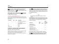
Service and Parts .......................................................................................................... 38
Energy Analyze Software ............................................................................................... 40
System Requirements ............................................................................................... 40
PC Connections ........................................................................................................ 41
Wiring Configurations..................................................................................................... 42
Specifications ................................................................................................................. 45

iii
List of Tables
Table Title Page
1. Symbols ................................................................................................................................ 4
2. Accessories .......................................................................................................................... 9
3. Front Panel ........................................................................................................................... 12
4. Connector Panel ................................................................................................................... 13
5. Power/Battery Status ............................................................................................................ 16
6. Replacement Parts ............................................................................................................... 38

1730
Users Manual
iv

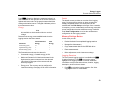
v
List of Figures
Figure Title Page
1. Country-Specific Mains Cords .............................................................................................. 5
2. Hanger Accessory ................................................................................................................ 6
3. Power Supply and Battery .................................................................................................... 7
4. R-Coil Operation Principle .................................................................................................... 10
5. Test Leads with Color Coding ............................................................................................... 11
6. Front Panel ........................................................................................................................... 12
7. Connector Panel ................................................................................................................... 13
8. Decal for Connector Panel .................................................................................................... 14
9. Replacement Parts ............................................................................................................... 39
10. Energy Logger to PC Connections ....................................................................................... 41
11. iFlex Probe Window .............................................................................................................. 51
12. i40s-EL Setup ....................................................................................................................... 53

1730
Users Manual
vi

1
Introduction
The 1730 Energy Logger (the Logger or Product) is a
compact device for energy surveys. With a built-in touch
screen and USB flash drive support, it is very easy to
configure, verify, and download measurement sessions
without the need of a computer at the measurement
location.
The Logger makes these measurements:
• Basic Measurements: Voltage (V), Current (A),
Frequency (Hz), Phase rotation indication, 2 dc
Channels (supports user-supplied external sensor for
other measurements such as temperature, humidity,
and air speed)
• Power: Active Power (W), Apparent Power (VA),
Non-active Power, (var), Power Factor
• Fundamental Power: Fundamental Active Power (W),
Fundamental Apparent Power (VA), Fundamental
Reactive Power (var), DPF (CosΦ)
• Energy: Active Energy (Wh), Apparent Energy (VAh),
Non-active Energy (varh)
• Demand: Demand (Wh), Maximum Demand (Wh),
Energy costs
• Harmonic Distortion: Total Harmonic Distortion of
Voltage and Current
Fluke Energy Analyze software is included with the
Product for a thorough energy analysis and professional
report of the measurement results.

1730
Users Manual
2
How to Contact Fluke
To contact Fluke, use one of these telephone numbers:
• USA: 1-800-760-4523
• Canada: 1-800-36-FLUKE (1-800-363-5853)
• Europe: +31 402-675-200
• Japan: +81-3-6714-3114
• Singapore: +65-6799-5566
• Anywhere in the world: +1-425-446-5500
Or, visit Fluke's website at www.fluke.com.
To register your Product, visit http://register.fluke.com.
To view, print, or download the latest manual supplement,
visit http://us.fluke.com/usen/support/manuals.
Go to www.flukenation.com for more information about
real-world applications and software downloads.
Safety Information
A Warning identifies hazardous conditions and
procedures that are dangerous to the user. A Caution
identifies conditions and procedures that can cause
damage to the Product or the equipment under test.
Warning
To prevent possible electrical shock, fire, or
personal injury:
• Read all safety information before you use
the Product.
• Use the Product only as specified, or the
protection supplied by the Product can be
compromised.
• Comply with local and national safety
codes. Use personal protective equipment
(approved rubber gloves, face protection,
and flame-resistant clothes) to prevent
shock and arc blast injury where
hazardous live conductors are exposed.
• Examine the case before you use the
Product. Look for cracks or missing
plastic. Carefully look at the insulation
around the terminals.
• Replace the mains power cord if the
insulation is damaged or if the insulation
shows signs of wear.

Energy Logger
Safety Information
3
• Use Product-approved measurement
category (CAT), voltage, and amperage
rated accessories (probes, test leads, and
adapters) for all measurements.
• Do not use test leads if they are damaged.
Examine the test leads for damaged
insulation and measure a known voltage.
• Do not use the Product if it is damaged.
• The battery door must be closed and
locked before you operate the Product.
• Do not work alone.
• Use this Product indoors only.
• Do not use the Product around explosive
gas, vapor, or in damp or wet
environments.
• Use only the external mains power supply
included with the Product.
• Do not exceed the Measurement Category
(CAT) rating of the lowest rated individual
component of a Product, probe, or
accessory.
• Keep fingers behind the finger guards on
the probes.
• Do not use a current measurement as an
indication that a circuit is safe to touch. A
voltage measurement is necessary to know
if a circuit is hazardous.
• Do not touch voltages >30 V ac rms,
42 V ac peak, or 60 V dc.
• Do not apply more than the rated voltage,
between the terminals or between each
terminal and earth ground.
• Measure a known voltage first to make
sure that the Product operates correctly.
• De-energize the circuit or wear personal
protective equipment in compliance with
local requirements before you apply or
remove the flexible current probe.
• Remove all probes, test leads, and
accessories before the battery door is
opened.

1730
Users Manual
4
Table 1 is a list of symbols used on the Product or in this
manual.
Table 1. Symbols
Symbol Description
Risk of Danger. Important information. See
manual.
Hazardous voltage
Conforms to relevant South Korean EMC
standards
Battery
Conforms to relevant Australian EMC standards
Conforms to relevant North American Safety
Standards
Conforms to European Union directives
Double Insulation
CAT II
Measurement Category II is applicable to test and
measuring circuits connected directly to utilization
points (socket outlets and similar points) of the
low-voltage MAINS installation.
CAT III
Measurement Category III is applicable to test
and measuring circuits connected to the
distribution part of the building’s low-voltage
MAINS installation.
CAT IV
Measurement Category IV is applicable to test
and measuring circuits connected at the source of
the building’s low-voltage MAINS installation.
This product contains a Lithium-ion battery. Do
not mix with the solid waste stream. Spent
batteries should be disposed of by a qualified
recycler or hazardous materials handler per local
regulations. Contact your authorized Fluke
Service Center for recycling information.
This product complies with the WEEE Directive
(2002/96/EC) marking requirements. The affixed
label indicates that you must not discard this
electrical/electronic product in domestic
household waste. Product Category: With
reference to the equipment types in the WEEE
Directive Annex I, this product is classed as
category 9 “Monitoring and Control
Instrumentation” product. Do not dispose of this
product as unsorted municipal waste. Go to
Fluke's website for recycling information.

Energy Logger
Before You Start
5
Before You Start
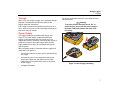
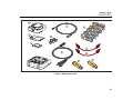
Below is a list of the items included with your purchase.
Carefully unpack and inspect each of the items:
• 1730 Energy Logger
• Power Supply
• Voltage Test Lead
• Dolphin Clip, Black
• i1730-flex1500 Thin-Flexi Current Probe, 30.5 cm (12 in)
quantity 3
• Color-coded Wire Clips
• Power Cord
(see Figure 1)
• Test lead with stackable plugs, 10 cm (3.9 in)
• Test lead with stackable plugs, 2 m (6.6 ft)
• DC Power Cable
• USB Cable A, Mini-USB
• Soft Storage Bag/Case
• Input Connector Decal
The power cord and input connector decal are
country-specific and vary according to the order destination.
See Figure 1.
• Documentation Info Pack (Quick Reference Card, Safety
Information, Battery Pack Safety Information, iFlex Probe
Safety Information, i40s-EL Current Clamp Safety
Information
• 4 GB USB Flash Drive (includes Users Manual and PC
application software, Fluke Energy Analyze)
Universal EuroNorth American/Japan United Kingdom
Australia/China Brazil
PN 1552374
PN 1552339 PN 4322049
PN 1552388
PN 1552342
hcf059.eps
Figure 1. Country-Specific Mains Cords

1730
Users Manual
6
Tilt Stand
The power supply includes a tilt stand. When used, the tilt
stand positions the display at a good angle for use on a
tabletop surface. To use, attach the power supply to the
Logger and open the tilt stand.
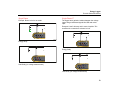
Hanger Accessory
The optional hanger accessory shown in Figure 2 is used
to:
• Hang the Logger with power supply attached (use two
magnets)
• Hang the Logger separately (use two magnets)
• Hang the power supply separately (use one magnet)
hcf058.eps
Figure 2. Hanger Accessory

Energy Logger
Storage
7
Storage
When not in use, keep the Logger in the protective storage
bag/case. The bag/case has sufficient space for the
Logger and all the accessories.
If the Logger is stored for an extended period of time or is
not in use for a long time, you should charge the battery at
least once every six months.
Power Supply
The Logger includes a removable power supply, see
Figure 3. The power supply is either attached to the
Logger or used externally with a DC power cord. The
configuration with the externally connected power supply is
preferred in locations where the Logger with the power
supply attached is too big to fit in a cabinet between the
door and panel.
When the power supply is connected with the Logger and
connected to line power, it:
• converts line power to dc power and is used directly by
the Logger
• automatically turns on the Logger and continuously
powers the Logger from the external source (after
initial power on, the power button turns on and turns
off the Logger)
• recharges the battery
The power cord/measurement line cover slides to select
the input source.
Warning
To prevent possible electrical shock, fire, or
personal injury, do not use the power supply if
the power cord/measurement line slide-cover
is missing.
hcf031.eps
Figure 3. Power Supply and Battery

1730
Users Manual
8
How to Charge Battery
The Logger also operates on an internal rechargeable
Lithium-ion battery. After you unpack and inspect the
Logger, fully charge the battery before first use.
Afterwards, charge the battery when the battery icon on
the screen indicates that power is low. The battery
automatically charges when the Logger is connected to the
mains power. The Logger continues to charge when
turned off and connected to mains power.
Note
The battery charge is faster when the Logger is
turned off.
To charge the battery:
1. Connect the mains cord to the ac input socket on the
power supply.
2. Fit the power supply to the Logger or use the dc power
cord to connect the power supply to the Logger.
3. Connect to mains power.
Caution
To prevent damage to the Product:
• Do not leave batteries unused for extended
periods of time, either in the product or in
storage.
• When a battery has not been used for six
months, check the charge status and
charge the battery as appropriate.
•
Clean battery packs and contacts with a clean,
dry cloth.
•
Battery packs must be charged before use.
•
After extended storage, it can be necessary to
charge and discharge a battery pack to obtain
maximum performance.
•
Dispose properly.
Note
• Li-ion batteries keep a charge longer if stored
at room temperature.
• The clock resets when the battery is
completely discharged.
• When the Logger shuts off because of low
battery, enough battery capacity is available to
back up the real-time clock for up to 2 months.

Energy Logger
Accessories
9
Accessories
Table 2 is a list of the accessories that are available and
sold separately for the Logger. The warranty on included
accessories is 1 year.
Table 2. Accessories
Description
Part
Number
i1730-flex 1500 Thin-Flexi Current Probe (single) 4345324
i1730-flex1500/3PK
Set of three Thin-Flexi Current Probes
1500 A 30.5 cm (12 in)
4357406
i1730-flex 3000 Thin-Flexi Current Probe (single)
4345616
i1730-flex3000/3PK
Set of three Thin-Flexi Current Probes
3000 A 61 cm (24 in)
4357414
i1730-flex 6000 Thin-Flexi Current Probe (single)
4345625
i1730-flex6000/3PK
Set of three Thin-Flexi Current Probes
6000 A 90.5 cm (36 in)
4357423
Fluke-1730 Test Lead, 0.10 m 4344653
Fluke-1730 Test Lead, 2 m 4344675
3PHVL-1730, Voltage Test Lead 3-phase + N, 4344712
i40s-EL Current Clamp, 40 A 4345270
i40s-EL/3PK, Set of three Current Clamps, 40 A 4357438
Fluke-1730-Hanger Kit 4358028
Lithium-ion Battery 4389436
Auxiliary Input Cable 4395217
C1730, Soft Case 4345187

1730
Users Manual
10
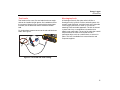
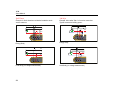
Thin-Flexi Current Probe
The Thin-Flexi Current Probe works on the Rogowski coil
(R-coil) principle that is a toroid of wire used to measure
an alternating current through a cable encircled by the
toroid. See Figure 4.
i(t)
v(t)
A
r
10 k
R3
330 k
R1
10 nF
C1
LF347
UI:A
1
GND
2
114
3
V
in
V
out
hcf028.eps
Figure 4. R-Coil Operation Principle
The R-coil has many advantages over other types of
current transformers:
• It is not a closed loop. The second terminal is passed
back through the center of the toroid core (commonly a
plastic or rubber tube) and connected along the first
terminal. This allows the coil to be open-ended,
flexible, and able to be wrapped around a live
conductor without disturbing it.
• It has an air core rather than an iron core. It has a low
inductance and can respond to fast-changing currents.
• Because it has no iron core to saturate, it is highly
linear even when subjected to large currents, such as
those used in electric power transmission or pulsed-
power applications.
A correctly formed R-coil, with equally spaced windings, is
largely immune to electromagnetic interference.

Energy Logger
Accessories
11
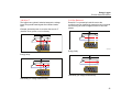
Test Leads
Test leads are four-core, flat, test leads that do not tangle
and can be installed in tight spaces. On installations where
the access to Neutral is out of reach with the three-phase
test lead, use the black test lead to extend the Neutral
lead.
For single phase measurements use the red and black test
leads. See Figure 5.
hcf025.eps
Figure 5. Test Leads with Color Coding
Kensington Lock
A Kensington Security Slot (also called a K-Slot or
Kensington lock) is part of a built-in anti-theft system. It is
a small, metal-reinforced, oval hole found on the right side
of the Logger (see item 6 in Table 3). It is used for
attaching a lock-and-cable apparatus. The lock is secured
in place with a key or combination lock attached to a
plastic-cover metal cable. The end of the cable has a small
loop that allows the cable to be looped around a
permanent object, such as a cabinet door, to secure it in
place. This lock is available from most electronics and
computer suppliers.

1730
Users Manual
12
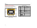
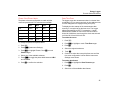
Navigation and User Interface
See Figure 8 and Table 3 for a list of the front panel
controls and their functions. See Figure 7 and Table 4 is a
list of the connectors and their functions.
2
1 8 7
5
4
3
6
9
hcf023.eps
Figure 6. Front Panel
Table 3. Front Panel
Item Control Description
Power on/off and status
Meter, Power, or Logger
function selection
Memory/Setup selection
Cursor control
Selection control
Kensington lock
Backlight on/off
Softkey selection
Touch screen display
Page is loading ...
Page is loading ...
Page is loading ...
Page is loading ...
Page is loading ...
Page is loading ...
Page is loading ...
Page is loading ...
Page is loading ...
Page is loading ...
Page is loading ...
Page is loading ...
Page is loading ...
Page is loading ...
Page is loading ...
Page is loading ...
Page is loading ...
Page is loading ...
Page is loading ...
Page is loading ...
Page is loading ...
Page is loading ...
Page is loading ...
Page is loading ...
Page is loading ...
Page is loading ...
Page is loading ...
Page is loading ...
Page is loading ...
Page is loading ...
Page is loading ...
Page is loading ...
Page is loading ...
Page is loading ...
Page is loading ...
Page is loading ...
Page is loading ...
Page is loading ...
Page is loading ...
Page is loading ...
Page is loading ...
Page is loading ...
-
 1
1
-
 2
2
-
 3
3
-
 4
4
-
 5
5
-
 6
6
-
 7
7
-
 8
8
-
 9
9
-
 10
10
-
 11
11
-
 12
12
-
 13
13
-
 14
14
-
 15
15
-
 16
16
-
 17
17
-
 18
18
-
 19
19
-
 20
20
-
 21
21
-
 22
22
-
 23
23
-
 24
24
-
 25
25
-
 26
26
-
 27
27
-
 28
28
-
 29
29
-
 30
30
-
 31
31
-
 32
32
-
 33
33
-
 34
34
-
 35
35
-
 36
36
-
 37
37
-
 38
38
-
 39
39
-
 40
40
-
 41
41
-
 42
42
-
 43
43
-
 44
44
-
 45
45
-
 46
46
-
 47
47
-
 48
48
-
 49
49
-
 50
50
-
 51
51
-
 52
52
-
 53
53
-
 54
54
-
 55
55
-
 56
56
-
 57
57
-
 58
58
-
 59
59
-
 60
60
-
 61
61
-
 62
62


Fluke 1730 Energy Logger Auxiliary Input Cable User manual
- Category
- Measuring, testing & control
- Type
- User manual
Ask a question and I''ll find the answer in the document
Finding information in a document is now easier with AI
Related papers
-
Fluke 1730 Hanger Strap Kit User manual
-
-
Fluke 1730-TL0.1M-testledning User manual
-
-
Fluke Three-Phase Power Quality Loggers 1742, 1746 dan 1748 User manual
-
-
-
-
-
Other documents
-
UNI-T UT658B USB Tester User manual
-
Elitech RC-5 Operation Instruction Manual
-
Comet R0110E User manual
-
-
-
 Ash iFlex User manual
-
 Hach Hach SL1000 Basic User Manual
-
Sharkoon 4044951008483 Datasheet
-
Major tech MT643 User manual
-
Omega OM-PLCV Owner's manual

