Page is loading ...

2251BR Intelligent Photoelectric
Smoke Sensor with Remote Test
Capability in Duct Applications
INSTALLATION AND MAINTENANCE INSTRUCTIONS
BEFORE INSTALLING
This sensor must be installed in compliance with the control panel system
installation manual. The installation must meet the requirements of the Au-
thority Having Jurisdiction (AHJ). Sensors offer maximum performance when
installed in compliance with the National Fire Protection Association (NFPA);
see NFPA 72.
GENERAL DESCRIPTION
Model 2251BR is a plug-in type smoke sensors that combines a photoelec-
tronic sensing chamber with addressable-analog communications. The sensor
transmits an analog representation of smoke density over a communication
line to a control panel. Rotary-decade switches are provided for setting the
sensor’s address.
Two LEDs on the sensor are controlled by the panel to indicate sensor status.
An output is provided for connection to an optional remote LED annunciator
(P/N RA400Z/RA100Z).
When 2251BR is used in duct applications with a DNR/DNRW, testing can be
done remotely using approved System Sensor test accessories, eliminating the
need for a test coil.
NOTE: Only System Sensor approved accessories may be used with the
2251BR.
The 2251BR requires compatible addressable communications to function
properly. Connect the 2251BR sensor to listed-compatible control panels only.
SPACING
System Sensor recommends spacing sensors in compliance with NFPA 72. In
low air flow applications with smooth ceilings, space sensors 30 feet apart.
For specific information regarding sensor spacing, placement, and special ap-
plications, refer to NFPA 72 or the System Smoke Detector Application Guide,
available from System Sensor.
Duct Applications: 2251BR is listed for use in ducts. See Duct Applications
Guide A05-1004-XX for details on pendant mount applications.
WIRING GUIDE
All wiring must be installed in compliance with the National Electrical Code,
applicable local codes, and any special requirements of the Authority Having
Jurisdiction. Proper wire gauges should be used. The installation wires should
be color-coded to limit wiring mistakes and ease system troubleshooting. Im-
proper connections will prevent a system from responding properly in the
event of a fire.
Remove power from the communication line before installing sensors.
1. Wire the sensor base (supplied separately) per the wiring diagram, Figure 1.
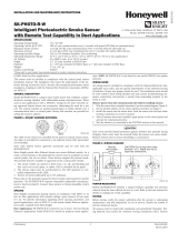
2. Set the desired address on the sensor address switches, see Figure 2.
3. Install the sensor into the sensor base. Push the sensor into the base
while turning it clockwise to secure it in place.
4. After all sensors have been installed, apply power to the control unit and
activate the communication line.
5. Test the sensor(s) as described in the TESTING section of this manual.
SPECIFICATIONS
Operating Voltage Range: 15 to 32 VDC
Standby Current: 300µA @ 24 VDC (one communication every 5 seconds with LED blink enabled)
Maximum Alarm Current (LED on:) 6.5 mA @ 24 VDC
Operating Humidity Range: 10% to 93% Relative Humidity, Non-condensing
Operating Temperature Range: 32°F to 120°F (0°C to 49°C) 2251BR
–4°F to 158°F (–20°C to 70°C) 2251BR in duct applications
Height: 2.0˝ (51 mm) installed in B210LP Base
Diameter: 6.1˝ (155 mm) installed in B210LP Base; 4.1˝ (104 mm) installed in B501 Base
Weight: 5.2 oz. (147 g)
Isolator Load Rating: 0.0063*
*Please refer to your isolator base/module manual for isolator calculation instructions.
CAUTION
Dust covers provide limited protection against airborne dust particles during
shipping. Dust covers must be removed before the sensors can sense smoke.
Remove sensors prior to heavy remodeling or construction.
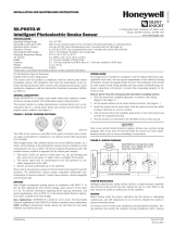
FIGURE 1. WIRING DIAGRAM:
2
3
1
2
3
3
1
2
1
(–)
(+)
+-
UL
LISTED COM
PATIBLE
CONTROL
PANEL
CAUTION: DO NOT LOOP WIRE
UNDER TERMINAL 1 OR 2.
BREAK WIRE RUN TO PROVIDE
SUPERVISION OF CONNECTIONS.
CLASS A OPTIONAL WIRING
REMOTE
ANNUNCIATOR
(–)
(+)
C0129-02
Note: Only System Sensor approved accessories may be used with the 2251BR.
FIGURE 2. ROTARY DECADE ADDRESS SWITCHES:
TENS ONES
9
8
7
6
5
4
3
2
1
0
9
8
7
6
5
4
3
2
1
0
C0146-00
TAMPER-RESISTANCE
Model 2251BR includes a tamper-resistant capability that prevents its removal
from the bracket without the use of a tool. Refer to the base manual for details
on making use of this capability.
TESTING
Before testing, notify the proper authorities that the system is undergoing
maintenance, and will temporarily be out of service. Disable the system to
prevent unwanted alarms.
All sensors must be tested after installation and periodically thereafter. Testing
methods must satisfy the Authority Having Jurisdiction (AHJ). Sensors offer max-
imum performance when tested and maintained in compliance with NFPA 72.
The sensor can be tested in the following ways:
A. Functional: Magnet Test (P/N M02-04-01 or M02-09-00)
This sensor can be functionally tested with a test magnet. The test mag-
net electronically simulates smoke in the sensing chamber, testing the
sensor electronics and connections to the control panel.
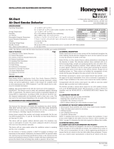
1. Hold the test magnet in the magnet test area as shown in Figure 3.
2. The sensor should alarm the panel.
I56-3534-005R
3825 Ohio Avenue, St. Charles, Illinois 60174
1.800.SENSOR2; Fax: 630.377.6495
www.systemsensor.com
3 I56-3534-005R
04-19

Two LEDs on the sensor are controlled by the panel to indicate sensor
status. Coded signals, transmitted from the panel, can cause the LEDs
to blink, latch on, or latch off. Refer to the control panel technical docu-
mentation for sensor LED status operation and expected delay to alarm.
B. Smoke Entry
The GEMINI model 501 aerosol generator can be used for smoke entry
testing. Set the generator to represent 4%/ft to 5%/ft obscuration as de-
scribed in the GEMINI 501 manual. Using the bowl shaped applicator,
apply aerosol until the panel alarms.
Additionally, canned aerosol simulated smoke (canned smoke agent)
may be used for smoke entry testing of the smoke detector. Tested and
approved aerosol smoke products are:
MANUFACTURER MODEL
Home Safeguard Industries 25S, 30S
SDi CHEK02 and CHEK06
SDi SOLOA4
SDi SMOKESABRE-01
When used properly, the canned smoke agent will cause the smoke detector
to go into alarm. Refer to the manufacturer’s published instructions for proper
use of the canned smoke agent.
CAUTION
Canned aerosol simulated smoke (canned smoke agent) formulas will vary by
manufacturer. Misuse or overuse of these products may have long term ad-
verse effects on the smoke detector. Consult the canned smoke agent manufac-
turer’s published instructions for any further warnings or caution statements.
C. Remote Test
2251BR can be remotely tested using the RTS451, RTS451KEY, RTS151, or
RTS151KEY test accessories. Refer to the DNR/DNRW manual for wiring
diagrams. Maximum test response time may be up to two communica-
tions from the panel.
A sensor that fails any of these tests should be cleaned as described under
CLEANING, and retested. If the sensor fails after cleaning, it must be replaced.
When testing is complete, restore the system to normal operation and notify
the proper authorities that the system is back in operation.
FIGURE 3. TEST MAGNET POSITION:
LED
TEST MAGNET
POSITION
MAGNET TEST
MARKER
LED
C0145-02
CLEANING
Before removing the detector, notify the proper authorities that the smoke
detector system is undergoing maintenance and will be temporarily out of
service. Disable the zone or system undergoing maintenance to prevent un-
wanted alarms.
1. Remove the sensor to be cleaned from the system.
2. Remove the sensor cover by pressing firmly on each of the four removal
tabs that hold the cover in place.
3. Vacuum the screen carefully without removing it. If further cleaning is
required continue with Step 4, otherwise skip to Step 7.
4. Remove the chamber cover/screen assembly by pulling it straight out.
5. Use a vacuum cleaner or compressed air to remove dust and debris from
the sensing chamber.
6. Reinstall the chamber cover/screen assembly by sliding the edge over the
sensing chamber. Turn until it is firmly in place.
7. Replace the cover using the LEDs to align the cover and then gently
pushing it until it locks into place.
8. Reinstall the detector.
9. Test the detector as described in TESTING.
10. Reconnect disabled circuits.
11. Notify the proper authorities that the system is back on line.
FIGURE 4. SENSOR ASSEMBLY:
SENSOR
COVER
SENSING
CHAMBER
COVER AND
SCREEN
COVER
REMOVAL
TABS
SENSING
CHAMBER
C0215-03
SPECIAL NOTE REGARDING SMOKE DETECTOR GUARDS
Smoke detectors are not to be used with detector guards unless the combina-
tion has been evaluated and found suitable for that purpose.
System Sensor warrants its enclosed smoke detector to be free from defects in materials and workman-
ship under normal use and service for a period of three years from date of manufacture. System Sensor
makes no other express warranty for this smoke detector. No agent, representative, dealer, or employee
of the Company has the authority to increase or alter the obligations or limitations of this Warranty.
The Company’s obligation of this Warranty shall be limited to the repair or replacement of any part of
the smoke detector which is found to be defective in materials or workmanship under normal use and
service during the three year period commencing with the date of manufacture. After phoning System
Sensor’s toll free number 800-SENSOR2 (736-7672) for a Return Authorization number, send defective
units postage prepaid to: Honeywell, 12220 Rojas Drive, Suite 700, El Paso TX 79936 USA. Please include
FCC STATEMENT
This device complies with part 15 of the FCC Rules. Operation is subject to the following two conditions: (1) This device may not cause harmful interference, and (2) this device must accept any interference
received, including interference that may cause undesired operation.
NOTE: This equipment has been tested and found to comply with the limits for a Class B digital device, pursuant to Part 15 of the FCC Rules. These limits are designed to provide reasonable protection against
harmful interference in a residential installation. This equipment generates, uses and can radiate radio frequency energy and, if not installed and used in accordance with the instructions, may cause harmful
interference to radio communications. However, there is no guarantee that interference will not occur in a particular installation. If this equipment does cause Harmful interference to radio or television reception,
which can be determined by turning the equipment off and on, the user is encouraged to try to correct the interference by one or more of the following measures:
– Reorient or relocate the receiving antenna.
– Increase the separation between the equipment and receiver.
– Connect the equipment into an outlet on a circuit different from that to which the receiver is connected.
– Consult the dealer or an experienced radio/TV technician for help.
THREE-YEAR LIMITED WARRANTY
a note describing the malfunction and suspected cause of failure. The Company shall not be obligated to
repair or replace units which are found to be defective because of damage, unreasonable use, modifica
-
tions, or alterations occurring after the date of manufacture. In no case shall the Company be liable for
any consequential or incidental damages for breach of this or any other Warranty, expressed or implied
whatsoever, even if the loss or damage is caused by the Company’s negligence or fault. Some states do
not allow the exclusion or limitation of incidental or consequential damages, so the above limitation or
exclusion may not apply to you. This Warranty gives you specific legal rights, and you may also have
other rights which vary from state to state.
Please refer to insert for the Limitations of Fire Alarm Systems
4 I56-3534-005R
©2016 System Sensor. 04-19
/