Nortek Contol SEG-1 User manual
- Category
- Networking
- Type
- User manual
This manual is also suitable for

Secure Ethernet Gateway
SEG-1 and SEG-M
for IEI Access Systems
Installation Manual
Section 1: Introduction
SECURITY WARNING: New SEG's shipped after April 2008 will have Telnet setup option enabled by default. Enabling Telnet on
the SEG allows you (the customer) to be able to configure the settings of the SEG via LAN without requiring the serial connection to
the SEG via the “Gateway Config” RJ11 adapter. While enabling Telnet setup was done as a convenience to speed setup, it also opens
a security hole in the SEG. It is recommended that when you are finished setting up the SEG, that you also enable the Telnet
password option, so that a password is required to enter Telnet in the future. This Telnet password option is located in Setup menu
option named “0 Server Configuration” and when you get to “Change telnet config password” enter Y and then enter a 4 digit
password. You can also completely disable Telnet in the menu named “6 Security”.
The SEG is a LAN/WAN (TCP/IP to serial) interface that enables existing or new IEI access systems to use the end user's network
infrastructure and to be programmed and managed at any network PC running Hub Manager™ Professional software. The SEG
requires Hub Manager™ Professional software version 5.0 or higher for static IP addressing and version 7.1 or higher for dynamic
addressing. The access system data sent over the corporate network is 128-Bit so that user and door information cannot be "sniffed"
and security compromised.
The IP address assigned to the SEG may be either a static address assigned by authorized network administrator, or it may be a
dynamic address assigned by a DHCP Server.
IMPORTANT NOTE:
To set up the SEG, installation technicians must have a technical knowledge of networks and networking in a PC environment. It is
important to consult the end user's system administrator in order to resolve any networking issues that may occur.
Ordering Information
Model p/n Description
SEG-1 0296005
IEI Secured Ethernet Gateway. Converts TCP/IP to serial data enabling IEI access
systems to use a network to securely send and receive data; and to be programmed and
managed from any network PC running Hub Manager Professional. Requires network
connection. Wall mounts using separately provided hardware; requires separate 12VDC
power [150 mA max], provided with modular cord for communication with access
panel.
SEG-M 0296006
IEI Secured Ethernet Gateway [Plug-in] Module. Converts TCP/IP to serial data
enabling IEI access systems to use a network to securely send and receive data; and to
be programmed and managed from any network PC running Hub Manager Professional.
Requires network connection. Easily plugs into backplane which provides module
power and communication with access panel.
Document Number: 6066005, Rev 3.2 Page 1 of 34

Table of Contents
Section 1: Introduction.............................................................................................................................1
Section 2: Product Overview...................................................................................................................3
2.1 Product Specifications...................................................................................................................3
2.2 LED Status....................................................................................................................................3
Section 3: Hardware Installation..............................................................................................................4
3.1 SEG-1 Diagrams...........................................................................................................................4
3.2 Connection the SEG-1 to a HubMax or Hub MiniMax (RS-232)...................................................5
3.2.1 SEG-1 to HubMax/Hub MiniMax Connection Method 1........................................................5
3.2.2 SEG-1 to HubMax/Hub MiniMax Connection Method 2........................................................5
3.3 Connecting the SEG-1 to HC500P (RS-232)................................................................................6
3.3.1 SEG-1 to HC500P Connection Method 1..............................................................................6
3.3.2 SEG-1 to HC500P Connection Method 2..............................................................................6
3.4 Connecting Multiple HubMax/Hub MiniMax Networks..................................................................7
3.5 Connecting the SEG-1 to a prox.pad plus (RS-485).....................................................................8
3.5.1 SEG-1 to prox.pad plus Connection Method 1......................................................................8
3.5.2 SEG-1 to prox.pad plus Connection Method 2......................................................................8
3.6 Connecting Multiple prox.pad plus Networks................................................................................9
3.7 Connecting the SEG-1 to a Max 3 System (RS-485).................................................................10
3.8 Connecting the SEG-1 to a MiniMax 3 System (RS-485)...........................................................11
3.9 SEG-M Installation (Plug On Module).........................................................................................12
3.9.1 SEG-M Diagram...................................................................................................................12
3.9.2 SEG-M Connectors..............................................................................................................13
3.9.3 SEG-M LED Indicators.........................................................................................................13
3.9.4 Connecting the SEG-M to a HubMax System (RS-232)......................................................14
3.9.5 Connecting the SEG-M to a Hub MiniMax System (RS-232)..............................................14
3.9.6 Connecting the SEG-M to a Max 3 System (RS-485).........................................................15
3.9.7 Connecting the SEG-M to a MiniMax 3 System (RS-485)..................................................16
Section 4: SEG Configuration................................................................................................................17
4.1 Dynamic IP Address via DHCP server, IP Address in SEG can change....................................17
4.2 Dynamic IP Address, non-expiring lease....................................................................................20
4.3 Static IP Address.........................................................................................................................21
4.3.1 Setting a Static IP Address of a SEG through a serial connection (via PC com port)........21
4.3.2 Setting a Static IP Address of a SEG via LAN (through a Telnet connection) ...................22
4.3.3 SEG Setup Menu.................................................................................................................24
4.3.4 Configuring the IP Address in Hub Manager Professional..................................................27
4.4 SEG Parameters.........................................................................................................................27
4.4.1 IP Address............................................................................................................................27
4.4.2 IP Port..................................................................................................................................27
4.4.3 SEG Serial Net Number.......................................................................................................27
4.4.4 Security Key.........................................................................................................................27
4.4.5 Generate Random Security Key..........................................................................................28
4.4.6 Generate Default Security Key............................................................................................28
4.4.7 Set This Security Key into the SEG.....................................................................................28
4.5 Defaulting the SEG Settings.......................................................................................................28
4.5.1 Reset the Security Key in the SEG to all 0's .......................................................................28
4.5.2 Reset the Security Key in the SEG to all 0's .......................................................................29
4.5.3 Reset the Security Key in the PC to all 0's..........................................................................29
Section 5: Trouble Shooting..................................................................................................................30
Section 6: FCC Compliance Statement.................................................................................................33
Page 2 of 34 Document Number: 6066005, Rev 3.2

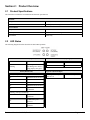
Section 2: Product Overview
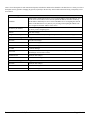
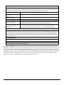
2.1 Product Specifications
The chart below contains the environmental and electrical specifications.
Electrical
Voltage 12VDC (9V Min; 20V Max)
Current 150mA @ 9V; 100mA @ 20V
Environmental
Temperature 0° to 70 ° C (32° to 158° F)
Humidity 0-95% RH Non-condensing
Environment Indoor Only
2.2 LED Status
The following diagram and chart describes the SEG LED operations.
Data Send/Recieve (Top Left) Network Link (Top Right)
Solid Idle
Flashing
Receiving data from
Hub Manager Pro and it is
being properly decrypted
Solid Good Network Link
Off No Network Link
Status (Bottom Left) Diagnostics (Bottom Right)
Solid (with top left blinking)
1x EEPROM Checksum Error
2x RAM Error
3x Network Controller Error
4x EEPROM Checksum Error
5x
Duplicate IP Address on
the Network
Flashing (with top left blinking)
4x Faulty Network
Connection
5x
No DHCP Response
Received
6x Software does not Match
Hardware
Flashing Alternately with
Bottom Left
Module is in Setup Mode
Document Number: 6066005, Rev 3.2 Page 3 of 34

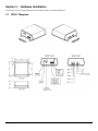
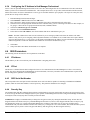
Section 3: Hardware Installation
The following section contains information about installing the SEG-1 and SEG-M hardware.
3.1 SEG-1 Diagrams
Page 4 of 34 Document Number: 6066005, Rev 3.2

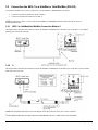
3.2 Connection the SEG-1 to a HubMax or Hub MiniMax (RS-232)
Two different methods can be used to connect Port A of the HubMax or HubMiniMax to the SEG-1:
1. Connect to the RS232 modular jack (front of SEG-1)
2. Connect to the RS232 terminals (rear of SEG-1)
NOTE: If connection to SEG-1 is NOT located at the HubMax or HubMiniMax then the connection must be made via
stranded/shielded cable.
3.2.1 SEG-1 to HubMax/Hub MiniMax Connection Method 1
The diagram below illustrates the method to connect the HubMax or HubMinimax to the RS232 port of the SEG-1 via its RS232
modular jack on the front of the unit.
3.2.2 SEG-1 to HubMax/Hub MiniMax Connection Method 2
The diagram below illustrates the method to connect the HubMax or HubMinimax to the RS232 port of the SEG-1via the terminal
block at the rear of the unit.
NOTE: The stranded shielded cable used in the diagram shows the connection to the SEG-1 across a distance.
*THIS CHART PERTAINS TO THE CABLE RUN BETWEEN THE SEG-1 AND IEI ACCESS SYSTEMS
Document Number: 6066005, Rev 3.2 Page 5 of 34

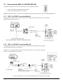
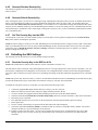
3.3 Connecting the SEG-1 to HC500P (RS-232)
Two different methods to can be used to connect Port A of the HC500P to the SEG-1
1. Connect to the RS232 modular jack (front of SEG-1)
2. Connect to the RS232 terminals (rear of SEG-1)
NOTE: If connection to SEG-1 is NOT located at the HC500P then the connection must be made via stranded/shielded cable.
3.3.1 SEG-1 to HC500P Connection Method 1
The diagram below illustrates the method to connect the HC500P to the RS232 port of the SEG-1 via its RS232
modular jack on the front of the unit.
3.3.2 SEG-1 to HC500P Connection Method 2
The diagram below illustrates the connections between the HC500P and the RS232 port of the SEG-1
via the terminal block at the rear of the SEG-1.
NOTE: The use of stranded shielded cable used in this diagram below is necessary when connecting
the SEG-1 at a distance from the controller.
Page 6 of 34 Document Number: 6066005, Rev 3.2

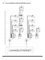
3.4 Connecting Multiple HubMax/Hub MiniMax Networks
Document Number: 6066005, Rev 3.2 Page 7 of 34

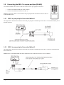
3.5 Connecting the SEG-1 to a prox.pad plus (RS-485)
Two different methods can be used to connect P5 Connector of the prox.pad plus to the SEG-1:
1. Connect to the RS485 modular jack (front of SEG-1)
2. Connect to the RS485 terminals (rear of SEG-1)
NOTE: If connection to SEG-1 is NOT located at the prox.pad plus then the connection must be made via
stranded/shielded cable.
3.5.1 SEG-1 to prox.pad plus Connection Method 1
The diagram below illustrates the method to connect the prox.pad plus to the RS485 port of the SEG-1 via its RS485 modular jack on
the front of the unit.
3.5.2 SEG-1 to prox.pad plus Connection Method 2
The diagram below illustrates the method to connect the prox.pad plus to the RS485 port of the SEG-1 via the TS1 terminal block at
the rear of the unit.
NOTE: The use of stranded/shielded cable in the diagram shows the connection to the SEG-1 across a distance.
Page 8 of 34 Document Number: 6066005, Rev 3.2

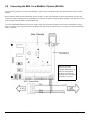
3.6 Connecting Multiple prox.pad plus Networks
Document Number: 6066005, Rev 3.2 Page 9 of 34

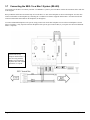
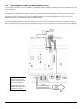
3.7 Connecting the SEG-1 to a Max 3 System (RS-485)
You can also use the SEG-1 to connect your Max 3 or MiniMax 3 system to your LAN/WAN. Follow the instructions below and refer
to the diagram.
Run your RS-485 cable between terminal strip TS1 on the SEG-1 to TS3 on the backplane as shown in the diagram. You must also
connect each module to the backplane by connecting the 3-conductor wire harness supplied with the Max 3 from P5 to the RS-485
connector underneath each module on the backplane (J1 through J4).
To connect additional backplanes to the system, simply connect TS3 on the first backplane to TS3 on the next backplane as shown
below. The SEG-1 is only required on the first backplane of the system (up to 64 doors Max; if you require more doors an additional
SEG-1 is required).
Page 10 of 34 Document Number: 6066005, Rev 3.2
Note: The maximum
distance between any
backplane and the SEG-1 is
4000 feet using 24AWG,
shielded, two twisted-pair
telephone cable with a shunt
capacitance of 16 pF/Ft.

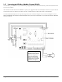
3.8 Connecting the SEG-1 to a MiniMax 3 System (RS-485)
You can also use the SEG-1 to connect your MiniMax 3 system to your LAN/WAN. Follow the instructions below and refer to the
diagram.
Run your RS-485 cable between terminal strip TS1 on the SEG-1 to TS3 on the backplane as shown in the diagram. You must also
connect the module to the backplane by connecting the 3-conductor wire harness supplied with the MiniMax 3 from P5 to the RS-485
connector underneath the module on the backplane (P1).
To connect additional backplanes to the system, simply connect TS3 on the first backplane to TS3 on the next backplane as shown
below. The SEG-1 is only required on the first backplane of the system (up to 64 doors Max; if you require more doors an additional
SEG-1 is required).
Document Number: 6066005, Rev 3.2 Page 11 of 34
Note: The maximum
distance between any
backplane and the SEG-1 is
4000 feet using 24AWG,
shielded, two twisted-pair
telephone cable with a shunt
capacitance of 16 pF/Ft.

3.9 SEG-M Installation (Plug On Module)
The SEG-M plug on module was created to allow HubMax and MiniMax panels an easier way to use the SEG-M functionality. When
used with HubMax or Hub MiniMax panels, no power or communication wiring is required between the SEG-M and the backplane.
All connections are made through the connector used to connect the SEG-M module to the backplane. To connect to a Max 3 or
MiniMax 3 you must use the supplied cable to make the connections to the module and the backplane.
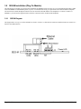
3.9.1 SEG-M Diagram
The diagram below is a top view of the SEG-M for reference. Section 3.9.2 describes the connectors and their functions. Section 3.9.3
describes the LED indicators.
Page 12 of 34 Document Number: 6066005, Rev 3.2

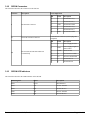
3.9.2 SEG-M Connectors
The chart below describes the connectors on the SEG-M.
Connector Description Pin Configuration
J1 RS-485 Data Connector
Pin Label Description
1 A RS-485 Data A (+)
2 B RS-485 Data B (-)
3 GND RS-485 Data GND
4 A RS-485 Data A (+)
5 B RS-485 Data B (-)
6 GND RS-485 Data GND
S1 Power/RS-232 Data Connector
Power/RS-232 Connector (used to plug onto
backplane)
TS1
RS-232 Data, RS-485 Data and Power
Terminal Strip
Pin Label Description
1 V+ Power Supply Positive
2 GND
Power Supply Negative/
Data Ground
3 EGND Earth Ground
4 A1 RS-232 Receive Data
5 A0 RS-232 Transmit Data
6 A RS-485 Data A
7 B RS-485 Data B
3.9.3 SEG-M LED Indicators
The chart below describes the LED indicators on the SEG-M.
LED Designator Label Description
LED1 Power SEG-M Power
LED7 TX RS-485 Transmit
LED5 RX RS-485 Receive
LED6 TX RS-232 Transmit
LED4 RX RS-232 Receive
Document Number: 6066005, Rev 3.2 Page 13 of 34

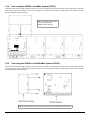
3.9.4 Connecting the SEG-M to a HubMax System (RS-232)
Connect the SEG-M to the eight-position pin rail S1 above the first module on the backplane. Make sure the components on the SEG-
M are facing away from the module. Use the two card guides to secure the SEG-M in place by snapping them into the holes on either
side and sliding the SEG-M into them.
3.9.5 Connecting the SEG-M to a Hub MiniMax System (RS-232)
Connect the SEG-M to the eight-position pin rail S1 on the left hand side of on the backplane. Make sure the components on the SEG-
M are facing away from the module. Use the two card guides to secure the SEG-M in place by snapping them into the holes on either
side and sliding the SEG-M into them.
Page 14 of 34 Document Number: 6066005, Rev 3.2
Note: No additional connections
are required between the
HubMax and the SEG-M.
Note: No additional connections are required between the Hub MiniMax and the SEG-M.

3.9.6 Connecting the SEG-M to a Max 3 System (RS-485)
You can connect your Max 3 to your LAN/WAN by using the SEG-M, Secured Ethernet Gateway. Follow the instructions below and
refer to the diagram.
The connection from the SEG-M to the Max 3 requires you to plug the module onto the backplane connector S1 to power the unit.
You must also use the six-conductor wire harness from J1 on the SEG-M to P5 on the module and J1 on the backplane. If you have
more than one module on the backplane, you must connect each module to the corresponding RS-485 connector (J2, J3 or J4)
underneath the module as described in the Max 3 Installation Manual.
To connect additional backplanes to the system, simply connect TS3 on the first backplane to TS3 on the next backplane as shown
below. The SEG-M is only required on the first backplane of the system (up to 64 doors Max; if you require more doors an additional
SEG-M is required).
Document Number: 6066005, Rev 3.2 Page 15 of 34
Note: The maximum
distance between the first
backplane with the SEG-M
and the next backplane is
4000 feet using 24AWG,
shielded, two twisted-pair
telephone cable with a shunt
capacitance of 16 pF/Ft.

3.9.7 Connecting the SEG-M to a MiniMax 3 System (RS-485)
You can connect your MiniMax 3 to your LAN/WAN by using the SEG-M, Secured Ethernet Gateway. Follow the instructions below
and refer to the diagram.
The connection from the SEG-M to the MiniMax 3 requires you to plug the module onto the backplane connector J2 to power the unit.
You must also use the six-conductor wire harness from J1 on the SEG-M to P5 on the module and P1 on the backplane.
To connect additional backplanes to the system, simply connect TS3 on the first backplane to TS3 on the next backplane as shown
below. The SEG-M is only required on the first backplane of the system (up to 64 doors Max; if you require more doors an additional
SEG-M is required).
Page 16 of 34 Document Number: 6066005, Rev 3.2
Note: The maximum
distance between the first
backplane with the SEG-M
and the next backplane is
4000 feet using 24AWG,
shielded, two twisted-pair
telephone cable with a shunt
capacitance of 16 pF/Ft.

Section 4: SEG Configuration
The SEG is a device created for the purpose of allowing data to be exported from your PC over a LAN/WAN to either Secured Series
Controllers or the prox.pad Plus. A minimal amount of setup must be performed on the SEG in order for it to be properly addressed on
the LAN.
There are 3 methods that can be used to configure the IP Address of the SEG:
1. Dynamic IP Addressing via DHCP server with an IP that can change (this is the recommended method but it requires SEG
firmware v1.30 or greater)
2. Dynamic IP Addressing via DHCP server with non-expiring lease (can be performed on any version of SEG)
3. Static IP Address (can be performed on any version of SEG)
NOTE: If your SEG has a firmware version of 1.30 or higher and there is a DHCP server on the network, which is typical, then it is
recommended that you refer to the section of this manual named Setting up a SEG that is assigned an IP Address by DHCP server.
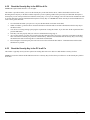
4.1 Dynamic IP Address via DHCP server, IP Address in SEG can change
This is the recommended method but it requires SEG v1.30 or greater firmware. The firmware label is located on top of the SEG.
NOTE: The SEG units that shipped prior to v1.30 did not have a version label on them. If the SEG you are setting up does not have a
version label, then the firmware is prior to v1.30 and you cannot use this method and you MUST use one of the other 2 methods to
assign an IP Address to that particular SEG.
Using this method, no manual setup of the SEG IP Address via the SEG serial port is required.
If you are installing more than one SEG on your LAN you just need to write down the 12 digit MAC Address located on the label of
the SEG and write down which controller group that SEG is connected to for reference. For example:
MAC Address Description
00-20-4A-52-F2-84 Building 1, Floor 2, HubMaxII
00-20-4A-52-8B-89 Building 1, Floor 7, HubMaxII
00-20-4A-52-F4-12 Building 2, Floor 1, prox.pad plus
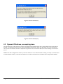
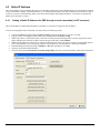
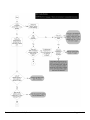
1. Press the button on the SEG setup screen (Fig. 1) labeled Search for SEG Devices to start the process.
2. A warning will be displayed (Fig. 2) reminding you what the firmware requirements are. Select Yes to continue the search.
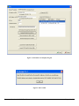
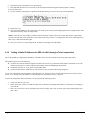
3. In approximately 5-10 seconds a grid will be filled with any SEG devices that were found (Fig. 3) and a message will be
displayed asking you to select a SEG in the grid (Fig. 4).
4. If you are only installing one SEG and it was found during the search simply select the item in the grid. If you have installed
more than one SEG then select the SEG that has the same MAC Address as the SEG you are setting up for this site.
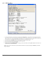
5. Now a message will be displayed asking you to generate a new Security Key (Fig. 5)
6. If you don't want to set the Security Key at this time then setup is complete, select save to Save and Close the Site Settings
screen.
7. If you want to change the Security Key, then select the button labeled 'Generate Random Security Key.
8. A message will then tell you to select the button labeled 'Set the Above Security Key into the SEG. (Fig. 6). Select that button
to send the new Security Key to the selected SEG.
9. Setup Complete
Now that the MAC address is known by Hub Manager Professional, if the DHCP server were to assign a new IP Address to this
particular SEG, then the next time you attempt to communicate with any of the controllers connected to this SEG, Hub Manager
Professional will retrieve the new IP Address from the SEG and will automatically save this new IP address into the Site Settings. This
saves you the time needed to reconfigure the IP Address in the Site settings screen.
Document Number: 6066005, Rev 3.2 Page 17 of 34

Page 18 of 34 Document Number: 6066005, Rev 3.2
Figure 1: No SEG parameters defined
Figure 2: SEG firmware requirements

Document Number: 6066005, Rev 3.2 Page 19 of 34
Figure 3: Found SEG's are displayed in grid
Figure 4: Select a SEG

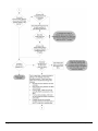
4.2 Dynamic IP Address, non-expiring lease
No setup of the SEG via the serial port is required. Just supply the SEG's MAC address (the 12 digit number located on the label on
the SEG; for example 00-20-4A-52-F2-84) to the IT department and ask them to assign it an IP Address with a non-expiring lease.
Once you have the IP address that the IT department assigned to the SEG, enter that IP address into the Site Settings screen and save
the site.
NOTE: Each SEG is shipped from the factory with an IP Address of 0.0.0.0. When the SEG is initially powered up (or rebooted) and
it has an IP address of all 0's, it will look for a DHCP server on the network and if one is found the SEG is assigned an IP Address.
Page 20 of 34 Document Number: 6066005, Rev 3.2
Figure 5: Generate Security Key
Figure 6: Generate Security Key
Page is loading ...
Page is loading ...
Page is loading ...
Page is loading ...
Page is loading ...
Page is loading ...
Page is loading ...
Page is loading ...
Page is loading ...
Page is loading ...
Page is loading ...
Page is loading ...
Page is loading ...
Page is loading ...
-
 1
1
-
 2
2
-
 3
3
-
 4
4
-
 5
5
-
 6
6
-
 7
7
-
 8
8
-
 9
9
-
 10
10
-
 11
11
-
 12
12
-
 13
13
-
 14
14
-
 15
15
-
 16
16
-
 17
17
-
 18
18
-
 19
19
-
 20
20
-
 21
21
-
 22
22
-
 23
23
-
 24
24
-
 25
25
-
 26
26
-
 27
27
-
 28
28
-
 29
29
-
 30
30
-
 31
31
-
 32
32
-
 33
33
-
 34
34


Nortek Contol SEG-1 User manual
- Category
- Networking
- Type
- User manual
- This manual is also suitable for
Ask a question and I''ll find the answer in the document
Finding information in a document is now easier with AI
Other documents
-
Geovision GV-COMV2 Datasheet
-
 MiniMax MA041118 Installation guide
-
Compaq Netelligent 2016 User manual
-
Quantum AML/J User guide
-
Eurotherm 900 User manual
-
mikroElektronika EasyPIC v7 User manual
-
Hitachi H8/3812 User manual
-
Samsung AN100JSKLKN Installation guide
-
Pioneer DEH-P646 Ser
-
Solid State Logic X-Logic User manual
