2903 - Installation instruction JOHN DEERE XUV550 Full Tilt Windshield revision 00 WWW.KOLPIN.COM
1
INSTALLATION INSTRUCTIONS
JOHN DEERE XUV550 FULL TILT WINDSHIELD
PART # 2903
Please read and understand these instructions completely before installation to avoid injury to yourself, damage to the vehicle or accessory.
Be certain to follow all specifications. For proper installation, two people are required
Dealer: These instructions contain important information for future reference and must be given to the customer at time of purchase or
upon completion of installation. Torque specifications must be followed when tightening bolts.
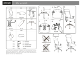
1. Parts List
Note that a few components of the vehicle are not depicted on the drawings in order to make the installation
instructions as clear as possible.
1. Installation
a) To apply the edge guard (Item C) to the lower windshield (Item B), find a
clean flat area where you can lay down the windshield. Partially remove the
protective film on both sides and apply the edge guard using manual
pressure to ensure good adhesion to the windshield.
b) To apply the foam cushion (Item D) to the upper windshield (Item A), find a clean flat area where you can lay down the windshield.
Partially remove the protective film and apply the self adhesive foam cushion using manual pressure to ensure good adhesion to the
windshield.
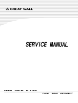
c) Attach clamps and upper pivot cylinder adaptors
(Item E, F & H) to the roll cage of your vehicle
as per drawings. The 2 lower clamp sets will be
used to attach the lower windshield and must be
installed with the threaded inserts facing the
front of the vehicle. The remaining (2) clamp
sets will be used to attach the upper windshield.
Install them by ensuring that the threaded inserts
are aligned from right to left of the roll cage.
Tighten all socket cap screws M6 x 45. Do not
tighten the screws that hold the clamp to the
roll cage; you will need to make adjustments
later on.
ITEM
PART NAME
DESCRIPTION
QTY
A
Upper windshield
CNC windshield cut-out made of ¼" thick GE MR10 polycarbonate or equivalent
1
B
Lower windshield
CNC windshield cut-out made of ¼" thick GE MR10 polycarbonate or equivalent
1
C
Edge guard for top lip & center arch
of lower windshield
Includes : 90" edge guard strip [end user to cut to exact length : 42 ½" for lower shield top lip, 44 ½"
for lower shield dash contour]
1
D
Foam cushion for upper windshield
Included : 42" of 1" x 1/8" self adhesive foam cushion [end user to cut to exact length]
1
INSTRUCTION
BAG
E
Clamp set (1 ¾")
Includes : 3 male clamp parts & 3 female clamp parts
2
F
Clamp set (1 ¾")
Includes : 2 male clamp parts & 2 female clamp parts
1
G
Nuts & bolts
Includes : 8 socket cap screws M6 x 20, 10 locknuts M6, 18 button head screws M6 x 18, 16 internal lock
washers M6, 16 plastic shoulder washers M6, 4 button head screws M6 x 45 & 2 ‘T’ knobs M6 x 35
1
H
Top pivot hinge of upper windshield
Includes : 2 x upper pivots & 4 x upper pivot cylinder adaptors
1
I
Slide arm and lower pivot of upper
windshield
Includes : 2 x slide arms 3 positions & 2 x lower pivot mounts
1
Dash contour 44 ½"
edge guard strip
Top lip 42 ½" edge
guard strip
41 ½’’ of self
adhesive foam
cushion
Detail #C1
(Next page)
Detail #C2
(Next page)
Threaded
inserts aligned
from right to left
of the roll cage
Threaded inserts
facing front of
vehicle

2903 - Installation instruction JOHN DEERE XUV550 Full Tilt Windshield revision 00 WWW.KOLPIN.COM
2
d) Install the lower windshield to all four lower clamps using supplied hardware (Item G) without applying final torque. Adjust the
position of the windshield and tighten all screws with specified torque indicated below. Ensure that the windshield is perfectly level
before tightening. If the windshield isn’t level, windshield functions will be affected. Over tightening clamps to roll bar could
cause parts failures.
e) To attach pivot components to upper windshield (Item A), as per step a), find a clean flat area where you can lay down the windshield.
Partially remove the protective film where components (Item H & I) are to be attached and follow drawings below. All screws that
are passing through the windshield will be tightened later in step f). Do not over-tighten the screws that combine the slide
arm with the lower pivot, those 2 parts need to swivel.
IMPORTANT :
Torque
specification
Max. 5 foot-pounds
Applicable to all
Clamp screws M6 x
20
(If torque tools are not
available, stop tightening
as soon as both male and
female clamp parts touch
as per picture below.)
Detail #C1
Female
clamp
parts
Locknuts
M6
Top pivot
cylinder
adaptor
Button head screw
M6 x 45
Male
clamp
parts
Socket cap
screws
M6 x 20
Detail #C2
Socket cap
screws
M6 x 20
Male
clamp
parts
Locknuts
M6
Female clamp
parts
Button head
screw
M6 x 18
Internal lock
washer M6
Shoulder
washer M6
Lower windshield
(step a))
Upper pivot
Shoulder
washer M6
Internal lock
washer M6
Button
head
screw
M6 x 18
Shoulder
washer M6
Internal lock
washer M6
Locknut
M6
Do not over-tighten the screws
that combine the slide arms with
the lower pivots, those parts
need to swivel.
Slide arm
Lower
pivot
Button
head
screw
M6 x 18

2903 - Installation instruction JOHN DEERE XUV550 Full Tilt Windshield revision 00 WWW.KOLPIN.COM
3
f) Attach upper windshield to the machine by following instructions below.
1. Make sure that both upper clamps are at the same height.
2. Hold the upper windshield horizontally and slide it down by ensuring that both upper
pivot cylinder adaptors are going through the upper pivot as per drawing #1.
3. Pull gently on the windshield as per drawing #2 towards the front of the vehicle for the
upper pivot to slide to the end onto the upper pivot cylinder adaptor.
4. Lower the windshield as per drawing #3 and the upper pivot will catch the second upper
pivot cylinder adaptor.
5. Adjust the height of the upper clamp first by ensuring the overall leveling.
6. Tighten all screws regarding the upper pivot.
7. Adjust the height of the clamp to the lower pivot and slide arm and use ‘T’ knob to lock
in place. Drawing #4 shows the position you should have when windshield is closed.
8. Tighten all remaining screws and nuts.
To operate the tilt mechanism:
Simply loosen both ‘T’ knobs (without removing them) and push on the upper windshield from the
inside of the cab until the desired position is reached. Then tighten knobs. Note that there are 3 pre-
determined positions on the slide arm; closed, half-opened and fully-extended.
The tilt mechanism is designed for cooling the airflow in warm temperatures.
Note that any open positions are designed for low-speed operation ONLY.
At high speed riding or when transporting the vehicle, the windshield must be closed.
To remove the upper windshield:
Remove both ‘T’ knobs and follow reverse instructions 4, 3 & 2 of step #f).
2. Maintenance and Care
Tighten all hardware after first use and periodically thereafter.
Failure to follow these installation instructions completely may void any warrantable components and result in product damage or personal
injury.
CLEANING:
Rinse with lukewarm water; wash gently with mild soap or detergent and lukewarm water, using a soft cloth or sponge. DO NOT SCRUB or use
brushes or squeegees.
Rinse again. Dry with soft cloth or moist cellulose sponge to prevent water spotting.
To remove wet paint, glazing compound or grease, rub lightly with a good grade of VM&P naphtha or isopropyl alcohol, then wash and rinse. DO
NOT USE GASOLINE.
NOTICE: Abusive cleaning procedures by hand washing or automated washing equipment will eventually result in visual hazing, loss of light
transmission and coating delamination.
Compatible Cleaning Agents
Aqueous Solution of Soaps and Detergents
- Fantastik1
- Joy2
- Neleco-Placer
- Hexcel, F.O. 554
- Windex5
- Formula 4091
- Lysol3
- Pine-Sol4
- Mr. Clean2
- Top Job2
Drawing #1
Drawing #2
Drawing #3
Drawing #4
/