Page is loading ...

Kerosene
#1 Diesel/
Fuel Oil
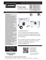
Congratulations!
You have purchased the finest indirect fired construction heater available.
Your new L.B. White heater incorporates the benefits from the most experienced
manufacturer of heating products using state-of-the-art technology.
We, at L.B. White, thank you for your confidence in our products and
welcome any suggestions or comments you may have...call us, toll-free,
at (800) 345-7200.
Owner's Manual and Instructions
Director™ Construction Heater
150-24287-A
MODELS OUTPUT (Btuh) FUEL
CP100AKI 100,000
CP300AKI 230,000
This heater has been designed and developed as a ductable indirect-fired forced air
construction heater with application for the temporary heating of buildings under
construction, alteration, or repair.
Additionally, this heater can be used for tent heating applications with temporary
human occupancy. If you are considering using this heater for any application other
than these intended uses, then please contact L.B. White Co. at (800) 345-7200.

GENERAL HAZARD WARNING
■Failure to comply with the precautions and instructions provided with this heater, can result in:
— Death
— Serious bodily injury or burns
— Property damage or loss from fire or explosion
— Electrical shock
■Read this Owner’s Manual before installing or using this product.
■Only properly-trained service people should repair or install this heater.
■Save this Owner’s Manual for future use and reference.
■Owner’s Manuals and replacement labels are available at no charge. For assistance, contact
L.B. White at 800-345-7200.
WARNING
Fire and Explosion Hazard
■Not for home or recreational vehicle use.
■Installation of this heater in a home or
recreational vehicle may result in a fire or
explosion.
■Fire or explosions can cause property
damage or loss of life.
FOR YOUR SAFETY
Do not store or use gasoline or other
flammable vapors and liquids in the vicinity of
this or any other appliance.
2
WARNING
Fire and Explosion Hazard
■Keep solid combustibles a safe distance
away from the heater.
■Solid combustibles include wood, paper, or
plastic products, building materials and
dust.
■Do not use the heater in spaces which
contain or may contain volatile or airborne
combustibles.
■Volatile or airborne combustibles include
gasoline, solvents, paint thinner, dust
particles or unknown chemicals.
■Failure to follow these instructions may
result in a fire or explosion.
■Fire or explosions can lead to property
damage, personal injury or loss of life.

Table of Contents
3
General Information
This Owner's Manual includes all options and accessories
commonly used on this heater.
When calling for technical service assistance, or for other
specific information, always have model number,
configuration number and serial number available. This
information is contained on the dataplate.
This manual will instruct you in the operation and care of
your unit. Have your qualified installer review this manual
with you so that you fully understand the heater and how it
functions.
The installation, repair and servicing of the heater requires
continuing expert training and knowledge of gas heaters
and should not be attempted by anyone who is not so
qualified. See page 6 for definition of the necessary
qualifications.
Contact your local L.B. White distributor or the L.B. White
Co., Inc. for assistance, or if you have any questions about
the use of the equipment or its application.
The L.B. White Co., Inc. has a policy of continuous product
improvement. It reserves the right to change specifications
and design without notice.
SECTION PAGE
General Information . . . . . . . . . . . . . . . . . . . . . . . . . . . . . . . . . . . . . . . . . . . . . . . . . . . . . . . . . . . . . . . . . . .3
Heater Specifications . . . . . . . . . . . . . . . . . . . . . . . . . . . . . . . . . . . . . . . . . . . . . . . . . . . . . . . . . . . . . . . . . .4
Safety Precautions . . . . . . . . . . . . . . . . . . . . . . . . . . . . . . . . . . . . . . . . . . . . . . . . . . . . . . . . . . . . . . . . . . . .5
Installation Instructions . . . . . . . . . . . . . . . . . . . . . . . . . . . . . . . . . . . . . . . . . . . . . . . . . . . . . . . . . . . . . . . .6
Operation Instructions
Theory of Operation . . . . . . . . . . . . . . . . . . . . . . . . . . . . . . . . . . . . . . . . . . . . . . . . . . . . . . . . . . . . . . .8
Fuels . . . . . . . . . . . . . . . . . . . . . . . . . . . . . . . . . . . . . . . . . . . . . . . . . . . . . . . . . . . . . . . . . . . . . . . . . . .8
Connecting Thermostat . . . . . . . . . . . . . . . . . . . . . . . . . . . . . . . . . . . . . . . . . . . . . . . . . . . . . . . . . . . .9
Start-Up Instructions . . . . . . . . . . . . . . . . . . . . . . . . . . . . . . . . . . . . . . . . . . . . . . . . . . . . . . . . . . . . . . . . .10
Shut-Down Instructions . . . . . . . . . . . . . . . . . . . . . . . . . . . . . . . . . . . . . . . . . . . . . . . . . . . . . . . . . . . . . . .10
Re-Start Instructions . . . . . . . . . . . . . . . . . . . . . . . . . . . . . . . . . . . . . . . . . . . . . . . . . . . . . . . . . . . . . . . . .10
Cleaning and Storage Instructions . . . . . . . . . . . . . . . . . . . . . . . . . . . . . . . . . . . . . . . . . . . . . . . . . . . . . .11
Maintenance Instructions . . . . . . . . . . . . . . . . . . . . . . . . . . . . . . . . . . . . . . . . . . . . . . . . . . . . . . . . . . . . .12
Service Instructions
Igniter Probe Gapping . . . . . . . . . . . . . . . . . . . . . . . . . . . . . . . . . . . . . . . . . . . . . . . . . . . . . . . . . . . . .12
Pump Pressure Check & Adjustment . . . . . . . . . . . . . . . . . . . . . . . . . . . . . . . . . . . . . . . . . . . . . . . .12
Setting for High Altitude . . . . . . . . . . . . . . . . . . . . . . . . . . . . . . . . . . . . . . . . . . . . . . . . . . . . . . . . . . .13
Troubleshooting Information . . . . . . . . . . . . . . . . . . . . . . . . . . . . . . . . . . . . . . . . . . . . . . . . . . . . . . . . . . .14
Electrical Connection and Ladder Diagram . . . . . . . . . . . . . . . . . . . . . . . . . . . . . . . . . . . . . . . . . . . . . . .15
Parts Identification
Parts Schematic . . . . . . . . . . . . . . . . . . . . . . . . . . . . . . . . . . . . . . . . . . . . . . . . . . . . . . . . . . . . . . . . .16
Parts List . . . . . . . . . . . . . . . . . . . . . . . . . . . . . . . . . . . . . . . . . . . . . . . . . . . . . . . . . . . . . . . . . .17 & 18
Warranty Policy . . . . . . . . . . . . . . . . . . . . . . . . . . . . . . . . . . . . . . . . . . . . . . . . . . . . . . . . . . . . . . . . . . . . . .19
Replacement Parts and Service . . . . . . . . . . . . . . . . . . . . . . . . . . . . . . . . . . . . . . . . . . . . . . . . . . . . . . . .19

SPECIFICATIONS
MMooddeell
Net Weight
Shipping Weight
Electrical Supply (Volts/Hz/Phase)
Dimensions (Inches)
L x W x H
Minimum Safe
Distances From
Nearest
Combustible
Materials
STARTING
CONTINUOUS
OPERATION
Motor Characteristics
Heater Specifications
Fuel Type
1 H.P. / 1,700 RPM
4
135 CFM
62 CFM
Ball Bearing
25 ft.
8 ft.
CP100AKI CCP300AKI
KKeerroosseennee,, ##11 DDiieesseell//FFuueell OOiill
115/60/1
- 20ºF
Amp Draw
.17 H.P. / 3,300 RPM
Max Input (BTUH) 105,000 300,000
Net Output (BTUH) 100,000 230,000
Ventilation Air Required
to Support Combustion
Air Flow (Hot) 883 CFM 1941 CFM
Pump Pressure 145 PSI 174 PSI
Fuel Consumption per Hour .77 Gallons 2.16 Gallons
6.5 30.0
2.0 10.0
41 x 20 x 46 47 x 27 x 62 1/2
TOP 8 ft.
SIDES 8 ft.
BACK 8 ft.
BLOWER
OUTLET
BULK FUEL
STORAGE CONTAINER
146 272
175 313
Minimum Ambient Temperature
in Which Heater May Be Used

5
Safety Precautions
1. Do not attempt to install, repair, or service this heater
unless you have continuing expert training and
knowledge of liquid fuel heaters.
Qualifications for service and installation of this
equipment are as follows:
To be a qualified liquid fuel heater service person, you
must have sufficient training and experience to handle
all aspects of indirect fired liquid fuel heater
installation, service and repair. This includes the task
of installation, troubleshooting, replacement of
defective parts and testing of the heater. You must be
able to place the heater into a continuing safe and
normal operating condition. You must completely
familiarize yourself with the heater by reading and
complying with the safety instructions, labels, Owner’s
Manual, etc., that is provided with each heater.
2. All installations and applications of L.B. White heaters
must meet all relevant local, state and national
codes. Included are electrical and safety codes. Your
local fuel supplier, a local licensed electrician, the
local fire department or similar government agencies,
or your insurance agent can help you determine code
requirements.
Refer to the following:
-- ANSI/NFPA 70, National Electrical Code.
-- ANSI A10.0, 1990 Safety Requirements for
Temporary and Portable Space Heating Devices
and Equipment Used in Construction Industry.
3. We cannot anticipate every use which maybe made of
our heaters. Check with the local fire safety authority
if you have questions about applications.
4. For safety, this heater is equipped with fan and high
limit switches. Never operate the heater with any
safety device that has been bypassed. Do not
operate this heater unless these features are fully
functioning.
5. Do not locate fuel containers near the blower outlet of
the heater.
6. Do not block air intakes or discharge outlets of the
heater. Doing so may cause improper combustion or
damage to heater components leading to property
damage.
7. Check for fuel leaks and proper function upon heater
installation, when relocating, and after servicing.
8. This heater should be inspected for proper operation
by a qualified service person before each use, not
less than once per shift, and at least annually.
9. This heater is equipped with a three-prong
(grounding) plug for your protection against shock
hazard and must be plugged directly into a properly
grounded three-prong receptacle. Failure to use a
properly grounded receptacle can result in electrical
shock, personal injury, or death.
10. Make certain you read and understand all warnings.
Keep this manual for reference. It is your guide to
safe and proper operation of this heater.
11. Use only kerosene, #1 diesel/fuel oil to avoid risk of
fire or explosion. Never use gasoline, naptha, paint
thinners, alcohol, or other higly flammable fuels.
12. Fueling:
a) Personnel involved with fueling shall be
qualified and thoroughly familiar with the
manufacturer’s instructions and applicable
regulations regarding the safe fueling of heating
units.
b) Use only the type of fuel specified on the heater’s
data plate.
c) All flame shall be extinguished and the heater
allowed to cool prior to fueling.
d) During fueling, all fuel lines and fuel-line
connections shall be inspected for leaks. Any leaks
shall be repaired prior to returning the heater to
service.
e) At no time shall more than one day’s supply of
heater fuel be stored inside a building in the vicinity
of the heater. Bulk fuel storage shall be outside
the structure.
f) All fuel storage shall be located a minimum of 25
feet from heaters, torches, welding equipment, and
similar sources of ignition (exception: the fuel
reservoir integral with the heater unit).
g) Whenever possible, fuel storage shall be confined
to areas where floor penetrations do not permit
fuel to drip onto or be ignited by a fire at lower
elevation.
h) Fuel storage shall be in accordance with the
authority having jurisdiction.
i) Fuel storage shall not be permitted within 10 ft. of
floor penetrations used for vertical access unless
separated from the penetration by full masonry
height walls.
13. Use only in areas free of flammable vapors or high
dust content.
14. Locate heater on a stable and level surface while hot
or operating.
15. Never start heater if fuel has accumulated in
combustion chamber.
16. Heater may start at any time when used with
thermostat.
17. When heater is moved or stored, it must be in a level
position or fuel spillage may occur.

18. Never move, handle, refuel, or service a hot,
operating, or plugged-in heater.
19. Never attach duct work to rear of heater.
20. Never attach heater to external fuel tank.
21. Heaters used in the vicinity of tarpaulins, canvas, or
similar enclosure materials shall be located in safe
distance from such materials. The recommended
minimum safe distance is 10 ft. It is further
recommended that these enclosure materials be of a
fire retardant nature. These enclosure materials shall
be securely fastened to prevent them from igniting or
from upsetting the heater due to wind action.
22. Unplug heater when not in use.
23. When the heater is used in an enclosed or partially
enclosed permanent or temporary structure, tests for
the presence of carbon monoxide shall be made
within one hour after the start of each shift, and at
least four hours thereafter. Immediate, more
frequent testing may be dictated by job conditions.
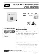
Installation Instructions
6
RAIN CAP
CHIMNEY
EXHAUST OUTLET
1. Read all safety precautions and follow L. B. White
recommendations when installing this heater. If
during the installation or relocating of heater, you
suspect that a part is damaged or defective, call a
qualified service agency for repair or replacement.
2. Install chimney, Part #24311 onto exhaust outlet.
Install raincap, Part #24223 (optional accessory)
onto chimney to protect against water entry when
heater is installed outside. See Fig. 1.
FIG. 1
3. This heater may be installed either indoors or
outdoors. For indoor installations, the heater must
be vented to outside. See Figs. 2 & 3 on page 7 for
chimney set-up and installation.
4. The heater may be ducted. Use only 20 ft. flexible
duct, Part #24220, and duct adapter, Part #24221.
Both parts are optional accessories. Do not use any
other length of duct, field fabricated ducts, or
adapters, stove pipes, etc. Locate the duct under
suitable wind barrier materials for jobsite
requirements.
5. When installed indoors, proper ventilation air must be
supplied to support the combustion of the heater.
Refer to Pg. 4 of this Owner’s Manual, or heater’s
dataplate for ventilation air requirements.
6. Insure all heater accessories have been installed.
7. The heater must be installed so as not to interfere
with or obstruct normal exits, emergency exits, doors
and walkways.
8. Railing, fencing or suitable substitute materials must
be used to keep the heating equipment from any
people using and visiting the structure.
9. The unit shall be located so that rain, ice, or snow
drainage from the structure does not affect
equipment operation. The heater must be mounted
above any pooled or standing water. A surrounding
trench is recommended to drain any rain, ice or snow
away from the unit.
10. The ground and surrounding terrain must be cleared
of any combustible vegetation and other combustible
materials when the heater is used.
11. Eventually, like all electrical/mechanical devices, the
thermostat can fail. Thermostat failure may result in
an underheating condition. The thermostat should be
tested to make sure it turns the heater on and off
within a temperature differential of ±3°F.
12. Take time to understand how to operate and maintain
the heater by using this Owner’s Manual. Make sure
you know how to shut off the power supply to the
heater.
13. Any defects found in performing any of the service or
maintenance procedures must be eliminated and
defective parts replaced immediately. The heater
must be retested by properly qualified service
personnel before placing the heater back into use.
EEXXTTEENNSSIIOONN CCOORRDD WWIIRREE SSIIZZEE RREEQQUUIIRREEMMEENNTTSS
FFOORR DDIIRREECCTTOORR 330000
■6 to 100 ft. long, use 14 AWG rated cord
■101 to 200 ft. long, use 12 AWG rated cord
■201 to 300 ft. long, use 10 AWG rated cord

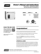
7
FIG. 3 VENTING TO OUTSIDE THROUGH WALL
FIG. 2 VENTING TO EXISTING CHIMNEY
A) Minimal 4 ft.
B) Minimal 4 ft.
C) The shortest
D) The same or bigger than the stacks outlet
diameter 4 ft. heater
E) Minimal 4 ft.
1) Anti-wind device provided with the heater
2) Horizontal crossing with minimal upside angle pitch of 5º
3) Chimney 51 in. x 51 in. of minimal inside measure
4) Chimney anti-explosion flap door
5) External seating wall
Note: The above information is a recommendation only. Have your
installation checked by local authority.

8
TTHHEE FFUUEELL SSYYSSTTEEMM
The motor turns the fuel pump. The fuel pump pulls fuel
from the fuel tank. The fuel pump pushes fuel through a
filter and a solenoid valve and out the burner head nozzle.
A fine mist of fuel is sprayed into the combustion chamber.
TTHHEE AAIIRR SSYYSSTTEEMM
The motor turns the fan. The fan pushes air into and
around the combustion chamber. This air is heated and
provides a stream of clean, hot air.
TTHHEE IIGGNNIITTIIOONN SSYYSSTTEEMM
The electronic ignitor sends voltage to the spark plug. The
spark plug ugnites the fuel and air mixture.
TTHHEE FFLLAAMMEE-OOUUTT CCOONNTTRROOLL SSYYSSTTEEMM
This system causes the heater to shut down if the flame
goes out. It also allows the fan to continue running after
normal shutdown of heater. This cools the combustion
chamber.
Operation Instructions
THEORY OF OPERATION
Do not use heavy fuels such as #2 fuel oil or #2 diesel.
Using heavy fuels will result in:
■Clogged fuel filter and nozzle
■Carbon build-up on spark plug
■The need of non-toxic anti-icer in fuel during very
cold weather.
Use a KEROSENE ONLY storage container. Be sure storage
container is clean. Foreign matter such as rust, dirt, or
water will cause flame-out control to shut down heater.
Foreign matter may also require you to clean fuel system
often.
FUELS
FIG. 4

To connect a thermostat refer to the following instructions:
a) Pull latch away from thermostat plug on control
panel.
b) Disassemble the plug.
c) Remove jumper at terminals 2 and 3. See Fig. 5.
(Keep the jumper. The jumper may be reinstalled
if manual operation of the heater is desired later.)
d) Remove plastic cap within strain relief.
e) Route thermostat cord set through strain relief,
support rings, and into plug. Thread strain relief
into plug housing.
f) Connect black and white wires to terminals 2
and 3, and green wire to ground terminal.
See Fig. 5.
g) Assemble thermostat plug and connect to control
panel.
CONNECTING THERMOSTAT
(Optional Accessory - Part #24219)
149
STRAIN RELIEF NUT
CAP (DISCARD TO ADD THERMOSTAT WIRING)
PLUG HOUSING
BLACK
REMOVE JUMPER WIRE
IN TERMINAL 2 AND 3
PLUG
SCREW
THERMOSTAT WIRE GREEN
WHITE
SUPPORT RINGS
FIG. 5
LOOSEN SCREWS TO
ADD THERMOSTAT WIRING
REAR SCREW SIDE FRONT PIN SIDE
21
3
2
1
3
REAR SCREW SIDE FRONT PIN SIDE

1. Turn thermostat dial to lowest temperature setting.
This will cause heater flame to go out. The motor will
continue to run during the purge cycle. This allows
the fan to cool the combustion chamber. When the
purge cycle is finished, the motor will stop. Do not
unplug heater until purge cycle is finished.
2. Unplug extension cord from outlet.
3. To temporarily stop heater, set thermostat at a
temperature lower than air around heater. Heater will
cycle back on if air temperature around heater
matches thermostat setting.
Shut-Down Instructions
CAUTION
■Never unplug heater while heater is running.
■The heater must go through purge cycle. The purge
cycle cools the combustion chamber.
■Damage to heater can occur if combustion chamber is
not cooled.
■Do not restart heater until purge cycle is complete.
1. Wait until purge cycle is finished after stopping
heater.
2. Repeat Start-Up Instructions.
Re-Start Instructions
CAUTION
Do not restart heater until purge cycle is finished. The
purge cycle cools the combustion chamber.
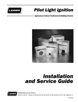
1410
RESET
POWER
OFF
ON THERMOSTAT
115V
60 Hz
WARNING
DISCONNECT HEATER FROM ITS ELECTRICAL
SUPPLY BEFORE REMOVING COVER
INDICATOR LIGHT INDICATOR LIGHT ON/OFF THERMOSTAT PLUG POWER CORD
1. Follow all ventilation and safety information.
2. Check that your electrical supply to the heater
conforms to the data plate, before heater operation is
attempted.
3. Fill tank with kerosene or #1 fuel oil and attach fuel
cap.
5. Connect heater to an approved electrical supply.
6. Set thermostat to the desired temperature.
7. Set switch to “ON” position. The motor will start
running, immediately followed by ignition.
8. When the unit is started for the first time or is started
after the fuel tank has been totally emptied, the flow
of fuel may be impaired by air in the circuit. In this
case the control box will shut down the heater and it
might be necessary to renew the starting procedure
once or twice by depressing the “Reset” button. To
facilitate starting, remove the canister bottom from
the pump’s fuel filter and fill with fuel. Reassemble
the filter.
NOTE: The unit is fitted with an electronic flame control
box. In case of malfunction this box will cut in and
stop the heater, at the same time the indicator light
in the control box reset button (1) will light up.
Heaters are also equipped with a high-limit safety
cut out which will stop the heater in case of
overheating. This thermostat will reset
automatically but you will have to depress the button
(1) on control box before being able to restart the
heater. If starting heater for first time, you may need
to restart heater several times before heater ignites.
You may also have to do this after taking heater out
of storage.
Start-Up Instructions
FIG. 6

1411
IINNIITTIIAALL PPRREEPPAARRAATTIIOONN
-- Disconnect electrical supply.
CCLLEEAANNIINNGG
The heater should have dirt or dust removed periodically:
a. Before each use give the heater a general
cleaning using compressed air or a soft brush or
dry rag on its case and internal components. At
this time, dust off the motor case to prevent
the
motor from over-heating.
b. At least once a year, give the heater a thorough
cleaning. At this time, remove the fan and motor
assembly and brush or blow off the fan blade
assembly. Additionally, make sure the burner air
venturi port is free of dust accumulation.
SSTTOORRAAGGEE
1. Drain all fuel from fuel filters, fuel lines, and pump.
2. Clean and flush fuel filter and canister attached to
fuel pump.
3. Remove drain plug and drain fuel tank. Replace drain
plug.
4. If any debris is noted in old fuel, add 1 or 2 quarts of
clean kerosene to tank, stir, and drain again. This will
prevent excess debris from clogging filters during
future use.
5. Replace fuel cap or drain plug. Properly dispose of
old and dirty fuel. Check with local automotive
service stations that recycle oil.
6. Add 2 gallons of kerosene or #1 fuel oil to fuel tank.
Replace fuel cap.
7. Operate heater for 5 minutes (See Operation
Instructions). Stop heater and let cool completely.
8. Remove drain plug and drain fuel tank. Replace drain
plug.
9. Properly dispose of old and dirty fuel.
10. Store heater in a dry location. Make sure storage
place is free of dust and corrosive fumes.
IIMMPPOORRTTAANNTT
Do not store kerosene over summer months for use during
next heating season. Using old fuel could damage heater.
WARNING
Do not use a pressure washer, water, or liquid cleaning
solution on any heater controls. Use of a pressure
washer, water, or liquid cleaning solution on the control
components can cause severe personal injury or
property damage due to water and/or liquids:
■In electrical components, and wires causing electrical
shock or equipment failure.
■On fuel pump and hose connections causing corrosion
which can result in fuel leaks and fire or explosion from
the leak.
Clean all components of the heater with pressurized air,
a dry brush, or a dry cloth.
Cleaning and Storage Instructions
WARNING
Fire, BBurn, aand EExplosion HHazard
■This heater contains electrical and mechanical components in the fuel management, and safety systems.
■Such components may become inoperative or fail due to dust, dirt, wear and aging.
■Periodic cleaning and inspection as well as proper maintenance are essential to avoid serious injury or property
damage.

PUMP
GAUGE
Service Instructions
IGNITER PROBE GAPPING
Ensure that gapping between spark electrodes is as shown
in Fig. 7. FIG. 7 1/8 in.
1. Remove pressure gauge plug from fuel pump port
marked “P” located in the upper right hand corner of
the pump. This requires a 4 mm allen wrench.
2. Install a pressure gauge that has 1/8-28 BSP (British
Straight Pipe) threads to the fuel port marked “P”.
3. Start heater (See Start-Up). Allow motor to reach full
speed. Pump pressure must be that given on
dataplate or Pg. 4 of Owner’s Manual.
4. To adjust pressure use 4mm allen wrench in the port
marked “P” located between the “-” and the “+” at
lower left area of the pump. Turn the allen head
clockwise towards the “+” to increase the pressure.
Turn counter clockwise towards the “-” to decrease
pressure.
5. Stop heater (See Shut-Down).
6. Remove pressure gauge. Replace pressure gauge
plug in fuel pump port marked “P” located in the
upper right hand corner of the pump body.
FIG. 8
PUMP PRESSURE CHECK & ADJUSTMENT
1. The area surrounding the heater shall be kept clear
and free from combustible materials, gasoline, and
other flammable vapors and liquids.
2. Check all wiring associated terminals and electrical
components within the heater for corrosion, frayed or
cut insulation, tight connections, etc. Repair or
replace as necessary.
3. Review all heater markings (i.e. wiring diagram,
warnings, start-up, shut-down, etc.) at the time of
maintenance for legibility. Make sure none are cut,
torn, or otherwise damaged. Any damaged markings
must be replaced immediately by contacting the L.B.
White Co., Inc. Dataplates, start-up and shut-down
instructions and warnings are available at no cost. A
nominal charge will be applied for wiring diagrams.
4. Inspect all fuel supply lines for cracks, abrasions, or
ruptures. Replace if needed.
5. The heater should be tagged and removed from
service if it shows evidence of damage that is a safety
or health hazard.
6. Refer to the following preventative maintenance
schedule:
Item Maintenance SSchedule
Fuel tank Flush every 50 hours of
operation or as needed
Fuel filter assembly Clean twice a heating season
(Fuel tank) or replace as needed
Fuel filter lines Check and tighten loose
connections before each use
Spark plug Clean and regap every
300 hours of operation or
replace as needed
Fan blades and Clean each season or
air deflectors as needed
Air passages Check each season for dirt
around burner head and debris. Remove debris
with a clean, soft cloth.
Maintenance Instructions
12

The heater may be operated at different altitudes.
Although there are not any parts that need to be changed,
you must set the air adjustment ring at the burner to
compensate for the change in altitude.
1. Remove the upper shell at the fan end of the heater.
2. Using a 5 mm. allen key, loosen the locking screw at
the ring. Slide the ring along the burner to open or
reduce the air opening for the specific altitude. See
Fig. 9. and refer to the following table for settings.
FIG. 9
Setting for High Altitude
AIR OPENING SETTING
ALTITUDE
(FEET)
1/2 in. 1/4 in. Up to 2,000
9/16 in. 5/16 in. 2,000 - 4,000
5/8 in.3/8 in.4,000 - 6,000
11/16 in. 7/16 in. 6,000 - 10,000
3/4 in. 1/2 in. 10,000 - 12,000
SCREW
AIR ADJUSTMENT RING
SLIDE RING FOR
PROPER AIR OPENING
DIRECTOR
100
DIRECTOR
300
13
AIR OPENING

READ THIS ENTIRE SECTION BEFORE BEGINNING
TO TROUBLESHOOT PROBLEMS.
This guide is intended for use by a QUALIFIED HEATER
SERVICE PERSON. DO NNOT AATTEMPT TTO SSERVICE TTHESE
HEATERS UUNLESS YYOU HHAVE BBEEN PPROPERLY TTRAINED.
TEST EEQUIPMENT RREQUIRED
The following pieces of test equipment will be required to
troubleshoot this system with minimal time and effort.
••DDiiggiittaall MMuullttiimmeetteerr - for measuring AC voltage and resistance.
••HHiigghh PPrreessssuurree GGaauuggee- for checking pressures at the fuel
pump against dataplate rating.
■Visually inspect equipment for apparent damage.
■Check all wiring for loose connections and worn
insulation.
Components should be replaced only after each step has
been completed and replacement is suggested in the flow
chart. Refer to the Servicing sections as necessary to
obtain information on disassembly and replacement
procedures of the component once the problem is identified
by the flow chart.
Troubleshooting Information
WARNING
■This heater can start at any time.
■Troubleshooting this system may require operating the
heater with line voltage present. Use caution when
working on the heater.
■Failure to follow this warning may result in property
damage, personal injury or death.
Problem Possible Cause Remedy
Motor does not start, No power - Check power supply (should be 115-120V /1/ 60 Hz)
no ignition - Check proper positioning and functioning of switch
- Check fuse
Wrong setting of room thermostat - Check correct setting of heater control. If thermostat is
or other control used make sure selected temperature is higher than
room temperature
Thermostat or other control defective - Replace control device
Motor defective - Replace motor
Motor bearings defective - Replace motor
Capacitor defective - Replace capacitor
Motor starts, no ignition Igniter defective - Check connection of spark igniter cable to electrodes
or cuts out and transformer
- Check electrodes setting
- Check electrodes for cleanliness
- Replace H.T. transformer
Flame control box defective - Replace control box
Photocell defective - Clean or replace photocell
Not enough or no fuel at burner - Check state of motor-pump plastic coupling
- Check fuel line system, including fuel filter, for
possible leaks
- Clean or replace oil nozzle
Solenoid defective - Check electrical connection
- Check thermostat LI
- Clean or replace solenoid
Motor starts, heater Not enough combustion air - Make sure air inlet and outlet are free
emits smoke - Check setting of combustion air flap
- Clean burner disc
Too much combustion air - Check setting of combustion air flap
Fuel contaminated or contains water - Drain fuel in tank, replace with clean fuel
- Clean oil filter
Air leaks in fuel circuit - Check fuel line and filter for possible leaks
Not enough fuel at burner - Check pump pressure
- Clean or replace fuel nozzle
Too much fuel at burner - Check pump pressure
- Replace nozzle
Heater does not stop Solenoid defective - Replace complete solenoid assembly
Motor does not stop Thermostat defective - Replace thermostat
14

Electrical Connection and Ladder Diagram
15
GROUND
TRANSFORMER
HI LIMIT
SOLENOID VALVE
PHOTO-CELL
FAN THERMOSTAT
CAPACITOR
FAN MOTOR
NL1
FUSE
HEATED FILTER
INDICATOR LIGHT
THERMOSTAT PLUG
IGNITION CONTROL BOARD
12345
678910
11 12
N
SWITCH RELAY
12345678910 11 12
115/60/1

Parts Identification
16
PARTS SCHEMATIC

PARTS LIST
17
Part Number
Item Description Director 100 Director 300
1 Handle 24712 24290
2 Leg, Support Frame 24713 24291
3 Plug 24292
5 Axle 24714 24293
6Wheel 24602 24294
7 Wheel Holder 24603 24295
8 Fuel Tank 24604 24296
9Drain Plug w/ Seal 24251
10 Drain Plug Seal 24298
11 Fuel Cap 24252
12 Fan Guard 24606 24300
13 Fan 24607 24253
14 Set Screw 24302
15 Motor Flange 24715 24303
16 Air Flap 24716 24304
17 Combustion Chamber 24718 24305
19 Outlet Cone 24719 24306
20 Base 24720 24307
21 Lower Shell 24721 24308
22 Upper Shell, Exhaust End 24722 24309
23 Upper Shell, Fan End 24723 24310
24 Chimney, Ø 150MM 24311
25 Bushing, Ø 35MM 23412
26 Bracket, Control Box 23413
27 Base, Control Box 24255
28 Control Box 24254
29 Transformer 24256
30 Ignition Cable 24257
31 Relay Finder 24258
32 Terminal Strip 24314
33 Electrical Components Drawer 24315
34 Pilot Lamp 24259
35 Switch 24260
36 Switch 24261
37 Thermostat Receptacle 25514
38 Receptable Cover 25515
39 Wire/Fuse Holder 24318
40 Fuse , 20 amp 24263
Fuse, 10 amp 24608
41 Power Cord 24319
42 Power Cord w/ Holder 24320
43 Fuel Line, Ø 6mm 24321
44 Bushing 24322
45 Hose, Compression Fitting, 1/4” Mx6 24323
47 Transition Fitting, 1/4” Mx6 24324
48 Transition Fitting, 1/8” Mx6 24325
49 Hose Nut, 3/8”x5 24326
50 Filter Support 24327
51 Male Pipe Fitting 24328
52 Transition Fitting, 90º, 3/8” Mx6 24609 24329
53 Oil Filter, Complete w/ Housing 24264
* BBold IItem Numbers IIndicate IImmediate PParts AAvailability.

18
PARTS LIST (cont.)
Part Number
Item Description Director 100 Director 300
54 Seal, Filter, Housing 24330
55 Seal, Filter, Upper 24331
56 Oil Filter 24265
57 Filter Housing 24266
58 Fan Switch, Thermostat 24724 24267
59 Limit Switch 24268
60 Electrode 24269
61 Ignition Boot 24332
62 Oil Supply Line, Ø 4mm 24610 24333
63 Pump 24725 24270
64 Solenoid Spool, BFP 11/21 24271
65 Solenoid Valve 24272
66 Straight Fitting, 1/4” Mx6 24273
67 Coupling 24629 24274
68 Transition Fitting, 90º, 1/8” Mx4 24275
69 Sleeve, Compression, 4mm 24276
70 Nut, Compression, 4mm 24277
71 Motor, with Capacitor 24630 24278
72 Capacitor 24631 24334
73 Straight Fitting, 1/8” Mx6 24632
74 Nut, M14 24336
75 Burner Flange 24727 24337
76 Orifice Holder 24338
77 Turbo Disc 24339
78 Orifice 24633 24279
79 Air Adjustment Ring 24634 24340
80 Photocell 24280
81 Clamp 24281
82 Flange, Photocell 24341
83 Screw, M5x16 24342
84 Screw, M6x55 24343
85 Nut, M6 24344
86 Nut, M5 24345
87 Screw, 8x3/8” 24346
88 Screw, M6x16 24347
89 Screw, 8x1 1/2” 24348
90 Screw, 4x1/2” 24349
91 Nut, M6 24350
92 Screw, M6x20 24351
93 Screw, 14x1/2” 24352
94 Nut, M5 24353
95 Screw, M5x35 24726 24354
96 Screw, 6x12” 24355
97 Screw, M4x8 24356
98 Screw, M6x25 24357
100 Screw, 4x3/8” 24358
101 Seal, Filter, Lower 24359
105 Burner Flange, Ø 102mm 24360
106 Oil Filter Cartridge w/ Seals 24282

19
Contact your local L.B. White dealer for replacement parts
and service or call the L.B. White Co., Inc. at (800) 345-
7200 for assistance. Be sure that you have your heater
model number and configuration number when calling.
L.B. White Co., Inc. warrants that the component parts of its
heater are free from defects in material and workmanship,
when properly installed, operated, and maintained in
accordance with the Owner’s Manual safety guides and
labels contained with each unit. If, within 112 mmonths ffrom
the ddate oof ppurchase bby tthe eend uuser, any component is
found to be defective, L.B. White Co., Inc. will at its option,
repair or replace the defective part or heater, with a new
part or heater, F.O.B., Onalaska, Wisconsin.
A warranty card on file at L.B. White will automatically
qualify the heater and its component parts for warranty
consideration. If a warranty card is not on file, a copy of the
bill of sale will be required to establish warranty
qualification. If neither is available, the warranty period will
be 12 months from date of shipment from L B. White.
Warranty Policy
Replacement Parts and Service
EQUIPMENT
PARTS
L.B. White Co., Inc. warrants that replacement parts
purchased from the company and used on the appropriate
L. B. White heater are free from defects both in material and
workmanship for 12 mmonths ffrom tthe ddate oof ppurchase bby
the eend uuser. Warranty is automatic if a component is found
defective within 12 months of the date code marked on the
part. If the defect occurs more than 12 months later than
the date code but within 12 months from the date of
purchase by the end user, a copy of a bill of sale will be
required to establish warranty qualification.
The warranty set forth above is the exclusive warranty
provided by L.B. White, and all other warranties, including
any implied warranties or merchantability or fitness for a
particular purpose, are expressly disclaimed. In the event
any implied warranty is not hereby effectively disclaimed
due to operation of law, such implied warranty is limited in
duration to the duration of the applicable warranty stated
above. The remedies set forth above are the sole and
exclusive remedies available hereunder. L.B. White will not
be liable for any incidental or consequential damages
directly or indirectly related to the sale, handling or use of
the heater, and in any event L.B. White's liability in
connection with the heater, including for claims based on
negligence or strict liability, is limited to the purchase price.
Some states do not allow limitations on how long an implied
warranty lasts, so the above limitation may not apply to you.
Some states do not allow the exclusion or limitation of
incidental or consequential damages, so the above
limitation or exclusion may not apply to you. This warranty
gives you specific legal rights, and you may also have other
rights which vary from state to state.
/