8 Vermont Castings • Intrepid II Installation & Operating Manual_R57 • 10/19 3-90-2000966
Double-wall Chimney Connector:
ThelistingfortheIntrepidIIfortheU.S.andCanadaincludes
useofdouble-wallchimneyconnectorsthathavebeentested
and listed for use with solid-fuel burning appliances by a
recognizedtestinglaboratory.
Information on assembling and installing double-wall
connector is provided by the manufacturer of the double-
wall pipe. Follow the manufacturer’s instructions exactly
as you assemble the connector and attach it to the stove
and chimney. Using connectors and chimneys from the
same manufacturer makes the assembly and installation
straightforward.
NOTE: For installations using double-wall connectors,
minimum clearances must conform to the listed
clearances in the clearance chart.
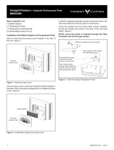
Single-wall Chimney Connector:
• Beginning at theue collarof the stove,assemble the
chimneyconnector.Inserttherstcrimpedendintothe
stove’suecollar,andkeepeachcrimpedendpointing
toward the stove. Using the holes in the ue collar as
guides, drill 1/8" (3 mm)
holes in the bottom of the
first section of chimney
connector and secure it to
theuecollarwiththree#10
x1/2"sheetmetalscrews.
• Secureeachjointbetween
sections of chimney
connector, including
telescoping joints, with at
least three sheet metal
screws.Thepre-drilledholes
in the top of each section of
chimney connector serve as
guideswhenyoudrill1/8"(3
mm)holesinthebottomof
thenextsection.
• Securethechimneyconnectortothechimney.Instructions
for various installations follow.
• Be sure the installed stove and chimney connector are
correct distances from nearby combustible material.
NOTE: Special slip pipes and thimble sleeves that form
telescopingjointsbetween sections ofchimneyconnector
are available to simplify installations. They often eliminate
the need to cut individual connector sections. Consult your
local dealer about these special pieces.
Securing the Single-wall Connector to a Prefabricated
Chimney:
Forprefabricatedchimneys,followtheinstallationinstructions
ofthechimneymakerexactlyasyouinstallthechimney.The
makerofthechimneywillsupplytheaccessoriestosupport
thechimney,eitherfromtheroofofthehouse,attheceilingof
theroomwherethestoveisinstalled,orfromanexteriorwall.
ST242
Chimney connector
12/13/99 djt
Figure 4 - The crimped
end of the connector points
toward stove.
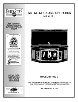
ST243
thinble connection
12/13/99 djt
Thimble Sleeve
Chimney
Connector
Flue
Keep
sleeve
endush
withue
tile
Figure 5 -Thethimble,madeofeitherceramicormetal,mustbe
cemented securely in place.
Freestanding Chimney Installations:
Ifthechimneyconnectormustpassthroughacombustible
walltoreachthechimney, follow the recommendationsin
theWallPass-throughsectionthatfollows.
The opening through the chimney wall to the flue (the
“breach”)mustbelinedwitheitheraceramicormetalcylinder,
calledthe“thimble,”whichiscementedrmlyinplace.The
tmustbesnugandthejointbetweenthethimbleandthe
chimneywallmustbecemented.(Figure6)
Aspecialpiececalledthe“thimblesleeve,”slightlysmaller
indiameterthanstandardconnectorandmostthimbles,will
facilitate the removal of the chimney connector system for
inspection and cleaning. Thimble sleeves should be available
fromyourlocaldealer.(Figure5)
Toinstallathimblesleeve,slideitintothebreachuntilitis
ushwiththeinneruewall.Donotextenditintotheactual
uepassage,asthiscouldinterferewiththedraft.
Thethimblesleeveshouldprotrude1-2"(25-50mm)intothe
room.Use furnacecement and thin gasketing toseal the
sleeve in place in the thimble. Secure the chimney connector
to the outer end of the sleeve with sheet metal screws.
Withoutathimble,asuitablelengthofchimneyconnector
canbeextendedthroughthebreachtotheinnerfaceofthe
ueliner,andcementedsecurelyinplace.Additionalpieces
of connector are then attached with sheet metal screws.
Special adapters are available from your local dealer to
maketheconnectionbetweentheprefabricatedchimneyand
the chimney connector. The top of such adapters attaches
directlytothechimneyortothechimney’sceilingsupport
package,whilethebottomoftheadaptorisscrewedtothe
chimney connector.
Theseadaptersaredesignedsothetopendwilltoutside
theinnerwallofthechimney,andthebottomendwilltinside
therstsectionofchimneyconnector.Whenassembledin
thisway,anysootorcreosotefallingfromtheinnerwallsof
the chimney will stay inside the chimney connector.
Securing the Single-wall Connector to a Masonry Chimney:
For masonry chimneys, both freestanding and replace
chimneysmaybeusedforinstallationofyourIntrepidII.