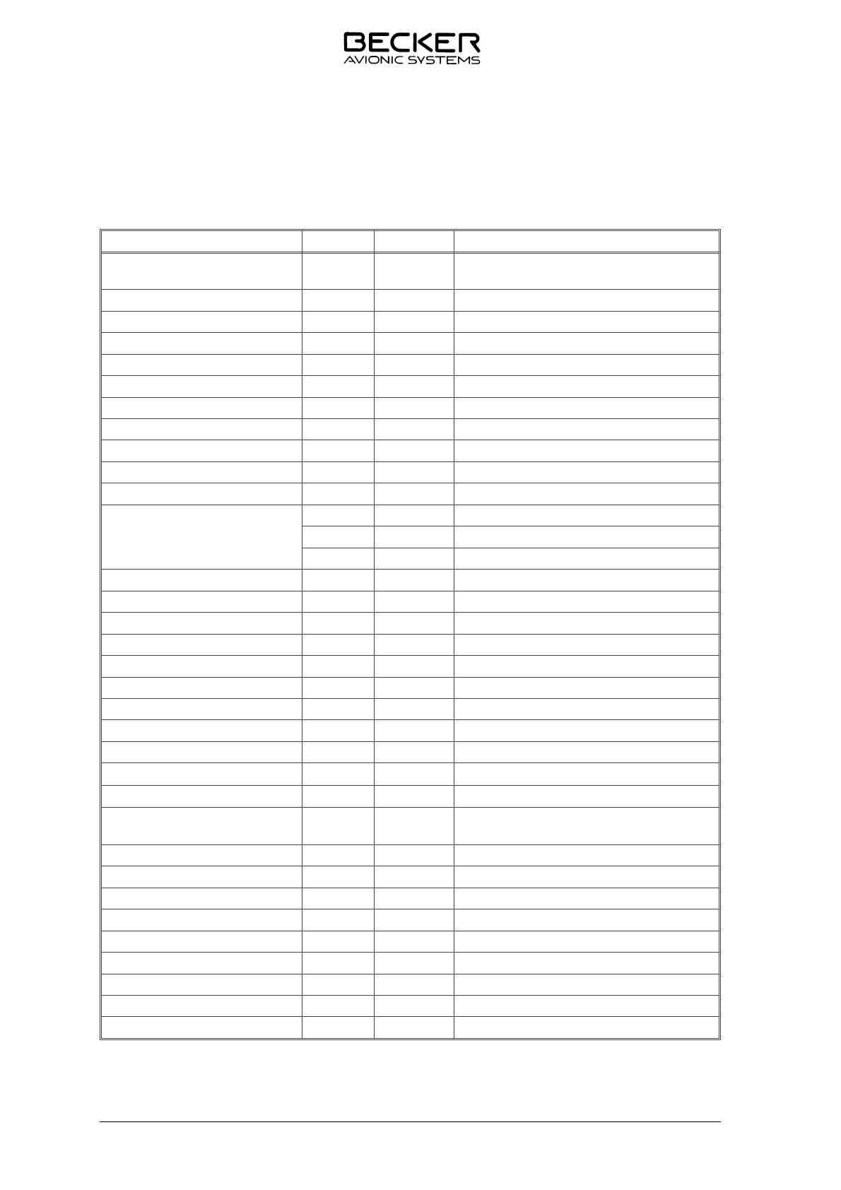
1.5.5 Environmental Qualification
The fol lo wing per for man ce stan dards un der en vi ron men tal test con di tions have been estab lis hed in
ac cor dan ce with the pro ce du res set forth in EU RO CAE/RTCA ED-14C/DO-160C Env. Cat. [A1D1]
-BA(MN)XXXXXXZBA BATZXXX.
En vi ron men tal con di ti on ED-14C/
DO-160C Ca te go ry Per for man -
ce
Tem pe ra tu re 4.0 A1 D1
Low ope ra ting tem pe ra tu re 4.5.1 - 20° C
Low ground sur vi val
(sto ra ge tem pe ra tur) - 55° C
High short-time ope ra ting
tem pe ra tu re 4.5.2 70° C
High ope ra ting tem pe ra tu re 4.5.3 + 55° C
High ground sur vi val
(sto ra ge) tem pe ra tu re 85° C
Min. ope ra ting pres su re
(equi va lent al ti tu de) 4.6.1 50.000 ft.
De com pres si on 4.6.2 from 8000 ft. to 50.000 ft. al ti tu de
Over pres su re 4.6.3 - 15.000 ft.
Tem pe ra tu re va ria ti on 5.0 B
Hu mi di ty 6.0 A 48 hrs at up to 50° C and 95%
re la ti ve hu mi di ty
Shock : 7.0
Ope ra tio nal shocks 7.2 11 ms at 6 G for all three di men sio nal axes
Crash sa fe ty shocks 7.3 11 ms at 15 G for all three di men sio nal axes
ac ce le ra ti on 12 G
Vi brat ion 8.0 MN
Mag ne tic ef fect 15.0 Z De flec ti on of 1° of com pass at a dis tan ce
of < 30 cm
Po wer in put va ria ti on 16.0 B Test con fir med that the equip ment functions
on a 20-volt emer gen cy po wer
supp ly
Re sis tan ce to vol ta ge spi kes
on equip ment po wer le ads 17.0 A
Au dio-fre quen cy con duc ted
sus cep ti bi li ty 18.0 B
Sus cep ti bi li ty to in du ced mag ne-
tic and elec tric fields at 400 Hz 19.0 Z
Ra dio-fre quen cy in ter fe ren ce
sus cep ti bi li ty 20.0 T
Spu ri ous RF emis sions 21.0 Z
ID 3502- ( )
Page 1-4 DV 30650.04 Issue 01/93


