Page is loading ...

TYAN S1672
Pentium Pro ATX
440FX PCI-ISA System Board
User's Manual
Revision 1.0

Dealer/Vendor_______________________________
Dealer/Vendor Number________________________
Dealer/Vendor Tech Support Number____________
Date Of Purchase____________________________
Please refer all tech support calls to your dealer/vendor.

Table Of Contents
1. Introduction....................................................................... 4
1.1 Overview................................................................4
1.2 Hardware Specifications..........................................5
1.3 Software Specifications.......................................... 6
1.4 Environment........................................................... 6
2. Board Installation.............................................................. 7
2.1 Unpacking.............................................................. 7
2.2 Installation.............................................................. 7
3. S1672 On Board Resource Settings................................. 8
3.1 S1672Board Layout & Jumper Locations................ 8
3.2 Quick Reference for Jumpers.................................. 9
3.3 CMOS RTC............................................................12
3.4 Flash EPROM Jumpers.......................................... 12
3.5 CMOS & Password Reset...................................... 12
3.6 DRAM Installation..................................................13
3.7 Voltage ID for Old Pentium Pro's............................ 13
3.8 Memory Table.........................................................14
3.9 CPU Installation.................................................... 15
3.10 VRM .................................................................. 16
3.11 Peripheral Device Installation................................. 16
3.12 Connecting The Power Supply...............................16
4. BIOS Configuration...........................................................17
4.1 Entering Setup....................................................... 17
4.2 Control Keys......................................................... 18
4.3 Getting Help........................................................... 19
4.4 The Main Menu...................................................... 19
4.5 Standard CMOS Setup Menu...................................21
4.6 BIOS Features Setup.............................................. 24
4.7 Chipset Features Setup............................................27
4.7.1 Power Management Setup........................28
4.8 PCI Slot Configuration.............................................30
4.9 Integrated Peripherals............................................. 32
4.10 Load Setup Defaults..............................................33
4.11 IDE HDD Auto Detection..................................... 35
4.12 Save & Exit Setup.................................................35
5. Flash Writer Utility............................................................ 36
5.1 The Flash Memory Writer Utility Screen...................38
6. System Resources............................................................. 39
6.1 Timer & DMA Channel Map................................... 39
6.2 Interrupt Map......................................................... 39

4S1672-ATX-001 http://www.tyan.com
1. Introduction
1.1 Overview
The S1672 is a quality, high performance mainboard designed for Intel
Pentium Pro microprocessors. This mainboard utilizes the Intel 440FX
chipset and can support CPU speeds of 150MHz through 200MHz.
The S1672's PCI Local Bus provides high performance capabilities that
are ideal for a wide range of demanding applications such as: CAD,
CAM, CAE, networking, multi-user environments, database management,
desktop publishing, image processing and 3D animation.
This integrated system board achieves high reliability with numerous
features and yet is small enough to be supported in a "ATX" form-factor.
Some of the features included are: on-board dual channel PCI PIO and
DMA IDE, on-board floppy controller, and on-board high speed I/O.
Flexibility and expandibility have been designed into the S1672. With I/O
and drive controller support built on-board, the four PCI and four ISA
(One ISA and one PCI as a shared slot) slots are free for numerous add-
on expansion cards.
Remember to take a look at Tyan Computers web site located at
http://www.tyan.com. Here you can find information on all of Tyan's
products along with FAQ's, distributors list, drivers and CMOS setting
explanations. If you have a tech support question please contact us at
www.tyan.com.
Notice
This board uses the Intel 440FX chipset. According to Intel , the USB
function in this chipset is not guaranteed. Compatibility tests cannot be
conducted for USB at this time due to no availability of such devices
and drives. Please log on to the Tyan web page for the latest infomation.

5S1672-ATX-001 http://www.tyan.com
1.2 Hardware Specifications/Features
wCPU Intel Pentium Pro 150 thru 200 MHz (Socket 8)
wCoprocessor On-chip floating point unit
wSpeed 60/66 MHz system bus
30/33 MHz PCI bus
7.5/8.33 MHz ISA bus speed
wDRAM 3 double banks of 72 pin SIMM sockets
Supports BEDO(Burst Extended Data Out)
Supports EDO(Extended Data Out) DRAMs
Supports ECC(Error Correcting Code)w/ parity
Supports Fast Page Mode DRAMs
Supports 8MB to 768MB of DRAMs
wL2 Cache 256/512KB 2nd level cache in CPU
wEIDE Controller Primary and secondary PCI EIDE channels on
board for support of up to four EIDE Mode 0
through Mode 4 drives.Supports DMA mode 1
and 2.
wEnhanced I/O Multi-mode bi-directional parallel port that
supports standard, EPP and ECP modes.
Supports 16550 compatible UARTS for on-board
high speed serial ports.
Support for an IrDA compliant InfraRed inter-
face.
On-board floppy controller.
On-board USB(Universal Serial Port).
wMouse On-board PS/2 mouse connector.
wI/O Bus Slots 4 Master/Slave PCI-Bus
4 ISA Bus (One ISA and one PCI shared slot)

6S1672-ATX-001 http://www.tyan.com
1.3 Software Specifications
wBIOS Award or AMI BIOS
AT CMOS setup, BIOS/CHIPSET setup,
and hard disk utility included.
Support for easy BIOS upgrades with flash
EEPROM chip.
wO.S. Operates with MS-DOS, Windows 3.x, Windows
for Work Groups 3.x, Windows 95, Windows NT,
OS/2, Novell Netware, Novell UnixWare 1.1 and
SCO Unix.
1.4 Environment
Ambient Temperature 0 to +50 C (operating)
Relative Humidity 0 to +85% (operating)
Altitude 0 to 10,000 feet (operating)
Vibration 0 to 1,000 Hz
Voltage 4.9 to 5.2 V
Information presented in this publication has been carefully checked for
reliability; however, no responsibility is assumed for inaccuracies. The
information contained in this document is subject to change without
notice.
Trademarks
Award BIOS/Flash are trademarks of Award Software International Inc.
AMI BIOS is a trademarks of American Megatrends Inc.
IBM,PC,AT,PS/2 are trademarks of IBM Corporation
INTEL,Pentium Pro are trademarks of Intel Corporation.
Copyright c 1996 TYAN Computer Corp.
S1672

7S1672-ATX-001 http://www.tyan.com
2. Board Installation
2.1 Unpacking
The mainboard package should contain the following:
wS1672 Mainboard
wOne IDE 40 pin cable
wOne 34 pin floppy cable
wUser's Manual
The mainboard contains sensitive electric components which can be easily
damaged by static electricity, so the mainboard should be left in its original
packaging until it is ready to be installed.
With the power supply pluged in and turned off touch an unpainted area of
the system chassis immediately before handling the mainboard or any com-
ponent. Doing so discharges the static charge your body may have built.
After opening the mainboard carton, extract the system board holding it by
its edges ,and place it only on a grounded anti-static surface, component
side up. Inspect the board for damage. Press down on all of the socket IC's
to make sure that they are properly seated. Do this only with the board
placed on an anti-static mat. Do not touch the bottom of the board.
DO NOT APPLY POWER TO THE BOARD IF IT HAS BEEN
DAMAGED!
2.2 Installation
You are now ready to install your mainboard. The mounting hole pattern of
the S1672 matches the ATX system board spec. It is assumed that the
chassis is for a standard ATX mainboard form factor.

8S1672-ATX-001 http://www.tyan.com
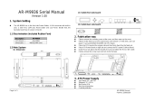
Com1 Com2
Parallel Port
PCI Slot 1
PCI Slot 2
PCI Slot 3
PCI Slot 4
ISA Slot2
ISA Slot3
ISA Slot 4
USB1
3. On Board Resource Setting
Figure 3.1 S1672 ATX Board Layout
PS/2
Mouse
PS/2
KB
82442FX
82441FX
CPU 0
Socket 8
Floppy Con.
ISA Slot 1
82371SB
Secondary IDE
Primary IDE
RTC
KB CTR
BIOS
AMI/AWARD
Bank 2
Bank 2
Bank 1
Bank 1
Bank 0
Bank 0
PWR On
IR
HD LED
PWR LED
Reset
Speaker
pin 1
pin 1
pin 1
pin 1
pin 1
{
J26
ATX PWR
AT PWR
J23
1
J22
USB2
J24
pin 1
J28
J29
Keylock
pin 1
J30
J32
J31
J33
J42
J43
J6
J14
J19
J20
J21
J4
J10
Con 7 Alt IR
pin 1

9S1672-ATX-001 http://www.tyan.com
3.2 Jumper Settings:
CPU Speed: J6, J33, J32, J31, J30, J19 & J20
CPU Speed J6 J33 J32 J31 J30 J19 J20
150MHz 3-4 off on on on on off
166MHz 1-2 off on on on off on
180MHz 3-4 on off on on on off
200MHz 1-2 on off on on off on
Host Bus Speed/PCI Bus Speed: J6, J19 & J20
Host Speed PCI Speed J6 J19 J20
60MHz 30MHz 3-4 on off
66.67MHz 33.33MHz 1-2 off on
CPU Clock Multiplier: J33, J32, J31 and J30
Multiplier J33 J32 J31 J30
X2 off off off off
X2.5 off on on on
X3 on off on on
X3.5 off off on on
X4 on on off on
CMOS Resest/Password Reset: J42(Default off)
If you forget your CMOS password or need to reset the
CMOS registers, just power off the system and close
jumper J42for five seconds. Then open jumper J42 and
power on the system. This will set the CMOS and password
back to the system default.

10S1672-ATX-001 http://www.tyan.com
Jumper Block J26:
1 Soft Power On
2 GND
3
4
5 Key
6 VCC
7 Key
8 Signal In
9 GND
10 Signal Out
11 VCC
12 Key
13 VCC
14 Key
15 Cathode
16 Anode
17 Key
18 Cathode
19 No Connect
20 Anode
21 Key
22 GND
23 Reset
24 VCC
25 GND
26 Key
27 Data
Infra Red Pins 6-11
Power On Pins 1-2
HDD LED Pins 15-16
Reset Pins 22-23
Speaker Pins 24-27
Power LED Pins 18-20
ATX/AT Power Connector Select: J4
Caution: Do not have J4 ON and have the ATX power connector installed at the
same time.
Connector J4
ATX off (default)
AT on

11S1672-ATX-001 http://www.tyan.com
Flash EEPROM: J43(Default 5V)
This jumper should be left at the factory default.
Voltage J32
5V 1-2 (default)
12V 2-3
Alt InfraRed Interface: Con 7
Pinout Assignment
1 Signal In
2 Gnd
3 Signal Out
4 VCC
Super I/O Type: J10
Type J10
665IR 1-2
669IR 2-3
This setting depends on what type of SMC I/O chip
is installed on the board. This jumper is set at the
factory and should not be changed.
CPU FAN Power: J14
Pinout Assignment
1 12Volts
2 Ground

12S1672-ATX-001 http://www.tyan.com
3.3 CMOS RTC
CMOS RTC includes an internal battery and Real Time Clock circuit. It
provides the date and the time for the system. Normally the life span of a
RTC internal battery is 10 years. When replacing, you should use the same
model.
3.4 Flash EEPROM-Jumper J43
The S1672 uses flash memory to store BIOS data. It can be updated as
new versions of the BIOS becomes available. The flash utility will guide
you through the process step by step. If your system is functioning properly,
you may want to forego updating your BIOS in the event the new one
causes problems with your existing hardware and software.
J43 determines which type of EPROM is used. This jumper has been set
to match the on board BIOS chip. The factory default for the S1672 is on
pins 1-2.
Refer to chapter 6 for Flash EEPROM upgrade procedures.
3.5 Hardware CMOS & Password Reset
(The following steps are valid provided the board has a DS12887A RTC)
If you have been locked out of your system because you forgot your pass-
word or set the CMOS incorrectly, follow the instructions below.
a. Power off the system
b. Short jumper J42.
c. Wait for 5 seconds then remove the jumper from J42.
d.Then power on the system again.
By doing the above procedures, your password will be erased and the CMOS
will be reset to the BIOS defaults.

13S1672-ATX-001 http://www.tyan.com
3.6 DRAM Installation
The S1672 uses a 64-bit data path from memory to CPU and can
accommodate up to 768 MB of RAM. The mainboard supports
standard, EDO (Extended Data Out) and ECC(Error Correcting Code)
72 pin SIMMS . All installed memory will be automatically detected so
there is no need to set jumpers.
wSIMM modules must be installed in pairs.
wEach pair of SIMMs must be of the same size and type.
wThe mainboard supports 1, 2, 4, 8, 16x32 or 32MBx32 SIMMS.
wThe table on the following page shows some of the available memory
configurations.
3.7 Voltage ID for Older Pentium Pro CPU's: J23
Most Pentium Pro CPU's will program the VRM to output
the correct voltage it requires, so these jumper are not important
and should be left open. Some early versions of the Pentium Pro
cannot program the VRM so you have to set these jumper manually.
J23 has eight pins and are numbered as follows.
5 6 7 8
1 2 3 4
Pin # 4--8 3-7 2-6 1-5
3.5V on on on on
3.4V on on on off
3.3V on on off on
3.2V on on off off
3.1V on off on on
3.0V on off on off
2.9V on off off on
2.8V on off off off
2.7V off on on on
2.6V off on on off
2.5V off on off on
2.4V off on off off
2.3V off off on on
2.2V off off on off
2.1V off off off on
Default off off off off

14S1672-ATX-001 http://www.tyan.com
3.8 Memory Table
Bank 0 Bank 1 Bank 2 Total
4MB x2 none none 8MB
8MB x2 none none 16MB
4MB x2 4MB x2 none 16MB
8MB x2 8MB x2 none 32MB
16MB x2 none none 32MB
16MB x2 16MB x2 none 64MB
32MB x2 none none 64MB
64MB x2 none none 128MB
32MB x2 32MB x2 none 128MB
32MB x2 32MB x2 32MB x2 192MB
64MB x2 64MB x2 none 256MB
128MB x2 none none 256MB
64MB x2 64MB x2 64MB x2 384MB
128MB x2 128MB x2 none 512MB
128MB x2 128MB x2 128MB x2 768MB

15S1672-ATX-001 http://www.tyan.com
1. Make sure the ZIF socket lever is up. To raise the lever, pull it out
to the side a little and raise it as far as it will go. The top plate will
slide back.
2. Align the CPU and socket Pin 1 corners. The pins on the bottom
of the CPU should align with the rows of holes in the socket.
3. Insert the CPU in the socket. It should insert easily. If it does
not, adjust the position of the lever a little.
4. Press the lever down. The top plate will slide forward. You will
feel some resistance as the pressure starts to secure the CPU in
the socket. This is normal and will not damage the CPU.
When the CPU is installed, the lever should snap into place at the
side of the socket in the down position.
3.9 CPU Installation
Many types of Pentium Pro (150 thru 200 MHz) CPUs can be used on
the S1672. Please refer to the previous pages for the correct CPU jumper
settings for your board.
w The CPU is a sensitive electronic component and it can be easily
damaged by static electricity. Do not touch the CPU pins with your
fingers.
w When installing the CPU into the socket, match the CPU pins to the
socket pins.
w Before the CPU is installed, the mainboard must be placed on a flat
plane in order to avoid being broken by the pressure of CPU insertion.
w A cooling fan and heat sink assembly is required to protect the
CPU from being damaged.

16S1672-ATX-001 http://www.tyan.com
3.10 VRM
The VRM is required for the Pentium Pro to work. The CPU will
program the VRM for the correct voltage needed. No jumper settings
are needed. The S1672 has a built in VRM so no installation is required.
3.11 Peripheral Device Installation
After all the jumpers on the mainboard have been set, then it can be mounted
into the case. Then proceed to install the display card and any other
peripheral devices.
If a PCI-Bus interface card is to be installed in the system, any one of the
four PCI-Bus slots can support either a Master or a Slave device.
After installing the peripheral controller, the user should check everything
again, and prepare to power-on the system.
3.12 Connecting the Power Supply & On/Off Switch
The system power supply connectors on the mainboard are for
standard ATX, and standard AT power supplies. The ATX connectors can
only be plugged in one way and should install in easily.
Use jumper J4 to select between ATX and AT power connector. By defualt
the S1672 has J4 set in the open position for ATX power connector. Just
close J4 for the AT connector.
ATX cases have an on/off switch that can be used to turn on or off
the ATX powersupply without having to use the switch that is on
the back of the powersupply.Use the jumper on J26 for the on/off button
from the system case.

17S1672-ATX-001 http://www.tyan.com
4. BIOS Configuration
Award's BIOS has a built in setup program that allows the user to modify
the basic system configuration. This type of information is stored in the
battery-backed CMOS SRAM. Entering incorrect information or for-
getting your password can lock you out of your system.(refer to 3.15
for resetting of CMOS)
4.1. Entering Setup
Power ON the computer and press <Del> immediately and you will enter
Setup. The other way to enter setup is to power on the computer, when the
below message appears briefly at the bottom of the screen during the post
(Power On Self Test), press <Del> key or simultaneously press <Ctrl>,
<Alt>, and <Esc> keys.
* TO ENTER SETUP BEFORE BOOT PRESS CTRL-ALT-
ESC OR DEL KEY
If the message disappears before you respond and you wish to enter Setup,
restart the system by turning it OFF then ON or by pressing "Reset" on the
system case. You may also restart by simultaneously pressing <Ctrl>, <Alt>,
and <Del> keys. If you do not press the keys at the correct time, the
system will not boot and an error message will appear on the screen.You
will be asked to,
* PRESS F1 TO CONTINUE, CTRL-ALT-ESC OR DEL TO
ENTER SETUP.
Figure 4.1 will appear on the sceen. The Main Menu allows you to select
from the 8 setup functions and 2 exit choices. Use the arrow keys to select
among the items and press <Enter> to accept or enter each sub-menu.

18S1672-ATX-001 http://www.tyan.com
4.2. Control Keys
PgUp key Increases the numeric value or make changes
PgDn key Decreases the numeric value or make changes
F1 key General help, only for Status Page Setup menu
and Option Page Setup Menu
F2 key Change color from a total of 16 colors
F3 key Calendar, only for Status Page Setup Menu
F4 key Reserved
F5 key Restore the previous CMOS value, only for Option
Page Setup Menu
F6 key Load defaults
F8 key Reserved
F9 key Reserved
F10 key Save all CMOS changes, only for Main Menu

19S1672-ATX-001 http://www.tyan.com
4.3. Getting Help
4.3.1. Main Menu
The on-line description of the highlighted setup function is displayed at the
bottom of the screen.
4.3.2. Setup Page menu/Option Page Setup Menu
Press F1 to pop up a small help window that describes the appropriate keys
to use and the possible selections for the highlighted items. To exit the Help
Window, press <Esc>.
4.4. The Main Menu
Once you enter the Award BIOS CMOS Setup Utility, the Main Menu
(Figure 4.4) will appear on the screen. The Main Menu allows you to
select from the eight setup functions and 2 exit choices. Use the arrow
keys to select among the items and press <Enter> to accept or enter the
sub-menu.
Figure 4.4: Main Menu
ROM ISA BIOS (2A59CT51)
CMOS SETUP UTILITY
AWARD SOFTWARE, INC.
ESC : Save & Exit Setup
F10 : Quit
(Shift)F2 :Change Color
:Select Item
Time, Date, Hard Disk Type,.....
STANDARD CMOS SETUP INTEGRATED PERIPHERAL
BIOS FEATURED SETUP SUPERVISOR PASSWORD
CHIPSET FEATURES SETUP USER PASSWORD
POWER MANAGEMENT IDE HDD AUTO DETECT
PNP/PCI CONFIGURATION SAVE AND EXIT
LOAD BIOS DEFAULTS EXIT WITHOUT SAVING

20S1672-ATX-001 http://www.tyan.com
ww Standard CMOS setup
This setup page includes all the items in a standard compatible BIOS.
ww BIOS features setup
This setup page includes all of the enhanced features of Award's BIOS.
ww Chipset features setup
This setup page includes all the items of the 430HX chipset features.
w Power Management setup
Change, set, or disable system power management options
ww PNP/PCI Configuration
This setup page allows you to modify the configuration of PCI slot
parameters.
ww Load setup defaults
BIOS defaults indicate the most appropriate values of each system param-
eter for your system.
ww Supervisor/User Password
Change, set, or disable password. It allows you to limit access to the
system and Setup.
ww Integrated Peripherals
This option lets the you enable or disable on board FDD, HDD,
and I/O options.
ww IDE HDD auto detection
Automatically configure hard disk parameters.
ww Save and exit setup
Save changes to CMOS and exit setup
ww Exit without saving
Abandon all CMOS changes and exit setup.
/