Page is loading ...

OPERATION, MAINTENANCE, AND INSTALLATION GUIDE
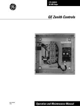
Zenith ZTX series
For ZTX series automatic transfer
switches, 30-1200 A, 200-480 Vac

2

2
1
—
Receiving, handling and storage
Receiving and handling
Upon receipt, carefully inspect the trans-
fer switch for damage that may have oc-
curred during transit. If damage is evi-
dent, or there is visible indication of
rough handling, immediately file a dam-
age claim with the transportation com-
pany, and notify your local ABB sales
office.
Do not remove the shipping packaging
until ready to install the switch.
Storage
If the unit will not be placed into service
immediately, store the transfer switch in
its original package in a clean, dry loca-
tion. To prevent condensation, maintain a
uniform temperature. Store the unit in a
heated building, allowing adequate air cir-
culation and protection from dirt and
moisture. Storing the unit outdoors could
cause harmful condensation inside the
transfer switch enclosure.
HAZARD OF EQUIPMENT
OVERTURNING
When moving with a fork lift, do not re-
move the shipping packaging until the de-
vice is in its final location.
Failure to follow this instruction may
result in personal injury or equipment
damage.
Warning
Indicates a hazardous situation that,
if not avoided, could result in death or
serious injury.

4
Zenith ZTX Series ATS, OPERATION, MAINTENANCE, AND INSTALLATION GUIDE
—
Read these safety instructions
carefully before using this product!
HAZARD OF ELECTRIC SHOCK,
EXPLOSION, OR ARC FLASH
• Apply appropriate personal protective
equipment and follow safe electrical
work practices.
• This equipment must only be installed
and serviced by qualified electrical per-
sonnel.
• Before performing visual inspections,
tests, or maintenance on the equip-
ment, disconnect all sources of electric
power. Assume that all circuits are live
unless they are completely de-ener-
gized, tested, grounded, and tagged.
Pay particular attention to the design of
the power system. Consider all sources
of power, including the possibility of
backfeeding.
• Disconnect all sources of electric power
before removing or making source side
or load side connections to the transfer
switch.
• Always use a properly rated voltage
sensing device at all line and load con-
nections to confirm transfer switch is
disconnected from all live electrical
sources.
• Turn off power supplying transfer
switch before doing any other work on
or inside switch.
Failure to follow these instructions could
result in death or serious injury.
Danger
Indicates a hazardous situation that,
if not avoided, will result in death or
serious injury.

5
12
—
Operation, maintenance,
and installation
instruction
Automatic transfer
switches, Zenith ZTX
series ATS
INSTALLATION INSTRUCTIONS,
ZENITH ZTX SERIES ATS,
CHAPTERS 9–11
OPERATION AND MAINTENANCE
INSTRUCTIONS, ZENITH
ZTX SERIES ATS,
CHAPTERS 1–8

6
Zenith ZTX Series ATS, OPERATION, MAINTENANCE, AND INSTALLATION GUIDE
1

7
1
—
Operation and
maintenance instruction
Automatic transfer
switches, Zenith ZTX
series ATS
1. Introduction 11
1.1 Hazard Categories 11
1.2 Definitions 12
1.3 Warranty 13
1.4 Product Specification 14
2. Product overview 15
2.1 General overview 16
2.1.1 Operation types 17
2.2 HMI 18
2.3 Zenith ZTX series features 19
2.4 Typical applications 22
2.5 Sequence of operations 24
2.5.1 Switching sequence / Automatic 24
2.6 Special features description 26
2.6.1 Automatic configuration 26
2.6.2 In-phase monitor 26
2.6.3 Powering supply scenarios 26

8
Zenith ZTX Series ATS, OPERATION, MAINTENANCE, AND INSTALLATION GUIDE
1
3. General operation 27
3.1 Position indication 27
3.2 Operating and locking 28
3.3 Manual handle operation 29
3.4 Return to automatic mode,
operating by HMI 30
3.5 LED functionality in HMI 31
3.6 Using Level 2 (DIP) control interface HMI 33
3.6.1 Keypad 33
4. Navigating HMI menu 35
4.1 Configuration by DIP switch 35
5. Electronic accessories 37
5.1 Using Ekip Connect -software 38
5.2 Using Ekip Bluetooth-module 39
5.2.1 LED indications 39
5.3 Using Ekip Programming -module 40
5.3.1 LED indications 40

9
1
6. Troubleshooting 41
6.1 Alarms 41
6. 2 Warnings 43
6. 3 Information 4 4
7. Technical data 45
7.1 General technical data 45
7.2 Circuit diagrams 48
7.3 Overall dimensions 49
8. Maintenance 53

10
Zenith ZTX Series ATS, OPERATION, MAINTENANCE, AND INSTALLATION GUIDE
1

11
1
—
1. Introduction
This manual describes the installation,
basic operation, and maintenance of
the Zenith ZTX series (30-1200A, 200-
480Vac) automatic transfer switches,
manufactured by ABB. Installation in-
structions for the transfer switch and
available accessories can be found in
chapters 9 and 10.
—
1.1 Hazard Categories
The following important highlighted in-
formation appears throughout this docu-
ment to warn of potential hazards or to
call attention to information that clarifies
a procedure.
Carefully read all instructions and become
familiar with the devices before trying to
install, operate, service or maintain
this equipment.
Danger
Indicates a hazardous situation that, if not
avoided, will result in death or serious injury.
Warning
Indicates a hazardous situation that, if not
avoided, could result in death or serious
injury.
Caution
Indicates a hazardous situation that, if not
avoided, could result in minor or moderate in-
jury. Failure to comply with these instructions
may result in product damage.
Notice
It is used to notify of practices not related to
personal injury. Failure to comply with these
instructions may result in product damage.

12
Zenith ZTX Series ATS, OPERATION, MAINTENANCE, AND INSTALLATION GUIDE
1
—
1.2 Definitions
ATS
Automatic transfer switches
Ekip
Electronic accessories / Ekip-modules
HMI
Control interface (Human Machine
Interface), operating and configuration
Programming port
Only for Ekip Programming and Ekip
Bluetooth -modules (USB port)
Slide switch
Switch for operating mode selection
(Hand - Locking - AUTO)
S1
SOURCE 1, power supply
S2
SOURCE 2, power supply
Zenith ZTX series ATS
Small frame residential, commercial, &
light industrial enclosed automatic
transfer switches, product name

13
1
—
1.3 Warranty
This document is based on information
available at the time of its publication.
While efforts have been made to ensure
accuracy, the information contained
herein does not cover all details or
variations in hardware and software,
nor does it provide for every possible
contingency in connection with
installation, operation, and maintenance.
Features may be described herein that are
not present in all hardware and software
systems.
ABB Zenith assumes no obligation of
notice to holders of this document with
respect to changes subsequently made.
ABB Zenith makes no representation or
warranty, expressed, implied, or
statutory, and assumes no responsibility
for the accuracy, completeness,
sufficiency, or usefulness of the
information contained herein. No
warrantees of merchantability or fitness
for purpose shall apply.
Contact your local sales office if further
information is required concerning any
aspect of the automatic transfer switch
operation or maintenance.
Warranty Period
The Warranty Period for ZTX series
transfer switch products is twelve (12)
months from the date of
shipment.
Notes: This warranty is valid only in the
United States and for products sold and
installed within seller-specified countries.
Replacement parts are warranted for a
period of 90 days when installed by a
factory or an authorized service station.
Contact Service team at: +1 800 637 1738

14
Zenith ZTX Series ATS, OPERATION, MAINTENANCE, AND INSTALLATION GUIDE
1
—
1.4 Product Specification
Quality Assurance
All ABB Zenith automatic transfer
switches have been designed and
manufactured to the highest technical
standards. Strict procedures ensure first-
class product quality.
Product Serial Number
Please have the serial number available
when communicating about the
automatic transfer switch. The serial
number can be found on the product
nameplate affixed to each power panel
assembly. See example below.
Product Rating / Applicable Standards
For UL 1008 ‘withstand’ and ‘close on
short circuit' ratings, refer to ABB
publication number 1SCC303020C0201,
"Zenith ATS, Powered by TruONE(TM)
Withstand and Closing Ratings (WCR)"
Figure 1.1: Sample nameplate
—
ZENITH ZTX
AUTOMATIC TRANSFER SWITCH FOR USE IN EMERGENCY SYSTEMS
Serial number
US1150191900002
Model number
ZXOG1BX12-AXXXXXXX
Voltage
Rated current
Frequency
Phase
Transition type
200 - 480 Vac
200 A
50/60 Hz
1 Phase
Open
Country of Origin
Finland
UL/Rating Label

15
1
The available operation types for automatic
transfer switches:
• Open (standard) transition Zenith ZTX series
ATS, type codes beginning ZXO_from 30-
1200 A, 200-480 Vac
—
2. Product overview
—
Zenith ZTX series automatic transfer switches, from 30 A
up to 1200 A, are designed for use in residential,
commercial, & light industrial low voltage automatic
transfer switch applications. Zenith ZTX series automatic
transfer switches can be operated electrically by DIP control
interface (HMI) or manually by using the handle. You can
select the operating mode by the slide switch (Hand -
Locking - AUTO) on switch front. Configuration is done
by DIP HMI.

16
1
Zenith ZTX Series ATS, OPERATION, MAINTENANCE, AND INSTALLATION GUIDE
1 Automatic transfer switch
2 Embedded ATS control unit and mechanism
3 HMI unit (ZTX DIP)
4 Slide switch (Hand - Locking - AUTO) for selection of the operation mode
5 Padlocking the automatic transfer switch to prevent automatic and
manual operation
6 Handle for manual operation
7 Position indication
8 Terminals for control circuit connections (behind the cover)
9 Place for auxiliary contact block
10 Location of product identification label
11 Programming port, only for Ekip Programming module and Ekip Connect software
—
Fig. 2.1 Automatic transfer switch, Zenith ZTX powered by TrueONE®
—
2.1 General overview
2
8 9
4
6
1
10
12
11
3
5 7

17
1
2.1.1 Operation types
In this table you can find the details on the
ZTX series operation type. For more infor-
mation on HMIs, see chapter 2.2 and for
wiring, see chapter 7.
Operation types, ZTX series ATS
Ekip-modules suitable
Open transition, ZTX
IS1 S2
Load
II
ZTX series HMI (with DIP-switches) and connections of control circuit
Lamp
test
l
ON
Off
load
test
ll
ON
Auto
Alarm reset
On
load
test
Bypass
time
delay
Dropout ∆U / ∆f
Manual
retransfer
Generator
stop delay
4 min
30 s
∆U 5% / ∆f 5%
∆U 10% / ∆f 5%
∆U 15% / ∆f 10%
∆U 20% / ∆f 10%
0
1
2
3
4
5
10
15
20
30
S1 Failure
delay
[s]
S1 Return
delay
[min]
On
Off
Auto
config
Start
Ok
Priority
No priority
Source 1
In-phase
monitor
Off
On
AUTO
!
S1 S2
LOAD
l
ll
Not Suitable
O1CC NO NC
1
2
3 65
G
—
Table 2.1 The differences of level types / operation
types and the suitability of Ekip-modules

18
1
Zenith ZTX Series ATS, OPERATION, MAINTENANCE, AND INSTALLATION GUIDE
The HMI is the control interface
(Human Machine Interface) of the ATS.
Zenith ZTX series has a DIP switch HMI
with push buttons. The HMI is used
for configuring parameters for
automatic operation.
—
2.2 HMI
I - II (or II - I)
ZTX:
HMI with
DIP switches
—
Fig. 2.2 HMI type
Lamp
test
l
ON
Off
load
test
ll
ON
Auto
Alarm reset
On
load
test
Bypass
time
delay
Dropout ∆U / ∆f
Manual
retransfer
Generator
stop delay
4 min
30 s
∆U 5% / ∆f 5%
∆U 10% / ∆f 5%
∆U 15% / ∆f 10%
∆U 20% / ∆f 10%
0
1
2
3
4
5
10
15
20
30
S1 Failure
delay
[s]
S1 Return
delay
[min]
On
Off
Auto
config
Start
Ok
Priority
No priority
Source 1
In-phase
monitor
Off
On
AUTO
!
S1 S2
LOAD
l
ll

19
1
—
2.3 Zenith ZTX series features
Feature comparison ZTX controls (DIP)
Lamp
test
l
ON
Off
load
test
ll
ON
Auto
Alarm reset
On
load
test
Bypass
time
delay
Dropout ∆U / ∆f
Manual
retransfer
Generator
stop delay
4 min
30 s
∆U 5% / ∆f 5%
∆U 10% / ∆f 5%
∆U 15% / ∆f 10%
∆U 20% / ∆f 10%
0
1
2
3
4
5
10
15
20
30
S1 Failure
delay
[s]
S1 Return
delay
[min]
On
Off
Auto
config
Start
Ok
Priority
No priority
Source 1
In-phase
monitor
Off
On
AUTO
!
S1 S2
LOAD
l
ll
Ampere sizes available UL: 30-1200 A
Rated voltage 200-480 Vac
Rated frequency 50 / 60 Hz
Phase system Single and Three
Number of poles 2, 3 and 4
Neutral configuration
Switched Yes
Product type
Open transition (I-II) Yes
Voltage and frequency settings
Pick up Voltage Source 1 Fixed 2% above drop out
Drop out Voltage Source 1 +/-5, 10, 15, 20 %
Pick up Voltage Source 2 Fixed 2% above drop out
Drop out Voltage Source 2 +/-5, 10, 15, 20 %
Pick up Frequency Source 1 Fixed 1% above drop out
Drop out Frequency Source 1 +/-5, 10 %
Pick up Frequency Source 2 Fixed 1% above drop out
Drop out Frequency Source 2 +/-5, 10 %
Time delay settings
Override momentary Source 1 Outage, sec 0, 1, 2, 3, 4, 5, 10, 15, 20, 30
Transfer from source 1 to source 2, sec 2 (0-3600 via Ekip Connect)
Override momentary Source 2 Outage, sec 1,5 (0-60 via Ekip Connect)
Transfer from source 2 to source 1, min 0, 1, 2, 3, 4, 5, 10, 15, 20, 30
Generator stop delay, min 30 secs or 4 mins

20
1
Zenith ZTX Series ATS, OPERATION, MAINTENANCE, AND INSTALLATION GUIDE
Feature comparison ZTX controls (DIP)
Lamp
test
l
ON
Off
load
test
ll
ON
Auto
Alarm reset
On
load
test
Bypass
time
delay
Dropout ∆U / ∆f
Manual
retransfer
Generator
stop delay
4 min
30 s
∆U 5% / ∆f 5%
∆U 10% / ∆f 5%
∆U 15% / ∆f 10%
∆U 20% / ∆f 10%
0
1
2
3
4
5
10
15
20
30
S1 Failure
delay
[s]
S1 Return
delay
[min]
On
Off
Auto
config
Start
Ok
Priority
No priority
Source 1
In-phase
monitor
Off
On
AUTO
!
S1 S2
LOAD
l
ll
Source failure detections
No voltage Yes
Undervoltage Yes
Overvoltage Yes
Phase missing Yes
Voltage unbalance Yes
Invalid frequency Yes
Incorrect phase sequence Yes
Features
Controls DIP + keys
LED indications for ATS, S1 and S2 status Yes
Open transition - Standard digital inputs/outputs 0 / 1
Programmable digital inputs/outputs No
Auto config (voltage, frequency, phase system) Yes
Source priority Source 1, No priority
Manual retransfer Yes
In-phase monitor (synchro check) Yes
Genset exercising: on-load, off-load Yes, via Ekip Connect
Load shedding No
Real time clock Yes
Event log Yes, via Ekip Connect
Predictive maintenance No
Harmonics measuring No
/