
Users
Guide
C28W40TN
C32W40TN

introduction
Dear HITACHI customer
Congratulations on your purchase of the very latest state of the art digital
technology. At Hitachi we pride ourselves on producing high quality digital
televisions with outstanding picture and audio capabilities, coupled with
Hitachi’s reputation for superior reliability. You should enjoy many years of
trouble free operation from your TV. Take some time to read this Users Guide
thoroughly, and if you encounter any difficulty, firstly refer to the Trouble
Shooting Guide at the rear of this manual. In the unlikely event of a problem
occurring with your TV, contact your dealer immediately.
DOLBY PRO LOGIC SURROUND SOUND*
Dolby Pro Logic Surround Sound is the domestic version of Cinema Dolby
stereo sound, and allows the viewer to enjoy full cinematic sound quality when
watching films or events recorded in Dolby Surround. The surround channels
reinforce the stereo image, allowing front to rear sound movements (such as
overhead aircraft effects) which immerses the viewer in ambience and special
effects. In addition to this, the Pro Logic circuitry is able to create a centre
channel - this anchors dialogue and central sounds to the screen so that
speech does not become disembodied or lost in sound effects.
Dolby Pro Logic together with Hitachi's unique 3DS Spatial Sound system will
allow you to enjoy the full Cinema Sound in your own home. In addition to this
your Hitachi TV has full expansion sockets to accommodate optional speaker
systems, so you can set up your listening area to match your most exacting
audio demands and aesthetic preferences. These features along with
outstanding picture quality and of course our reputation for superior reliability
will continually reward your decision for choosing HITACHI.
*Manufactured under license from Dolby Laboratories Licensing Corporation.
DOLBY, the double-D symbol and PRO LOGIC are the trademarks of Dolby
Laboratories Licensing Corporation.
...notes on illustrations
The model illustrated throughout this Users Guide is the C28W40TN.
This model differs only cosmetically from other models covered by this guide,
but all the functions and controls remain the same.
digital circuitry
To maintain efficient working temperature of your TV’s digital circuitry and
prolong component life Hitachi have installed an integral cooling fan into your
TV. Therefore on low TV volumes you may hear a slight background noise

contents
page
contents
Television Safety ....................................................................4
Battery Safety and Installation................................................5
Aerial and VCR Installation ....................................................6
Aerial, Satellite and VCR Installation ......................................7
Television Control Panel ........................................................8
Camcorder and Computer Connection .................................9
External Equipment Connection............................................10
Handset Controls - Program Tuning ....................................12
Automatic Tuning Procedure and Digital Program Swap ......13
Automatic Tuning Procedure and Digital Program Delete ....14
Manual Tuning Procedure - Analogue ..................................15
Program Name Change........................................................17
Program Swap......................................................................18
Picture Controls ....................................................................19
Signal Source Entry ..............................................................20
Audio and Equaliser Controls................................................22
Features - Sleep Timer and Wide Screen ............................24
Sound Mode ........................................................................27
Hitachi 3DS Sound System ..................................................28
Sound Features ....................................................................29
Speaker Setup ......................................................................30
Surround Setup ....................................................................31
AV Setup ..............................................................................32
Handset Controls - Television Operation ..............................33
Handset Controls - Teletext Functions ................................34
Teletext Operation ................................................................35
Digital - Personal Identification Number................................36
Digital Autotune ....................................................................37
Digital - Locking Channels ....................................................38
Digital Organiser - Program Swap ........................................39
Digital Organiser - Program Delete ......................................40
Digital - Record Event Entry..................................................41
Digital Modem Set-Up ..........................................................43
Digital Software Upgrade......................................................45
Handset Controls - Digital TV features..................................46
Digital Features - TV Guide ..................................................47
Digital Features - TV information ..........................................48
Trouble Shooting Guide ........................................................49
Guarantee ............................................................................50
Technical Data ......................................................................51

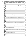
television safety
4
This television has been designed and manufactured to meet international
safety standards, but like any electrical equipment, care must be taken if
you are to obtain the best results and safety is to be assured - so please
read this users guide before you attempt to install and use this equipment.
DO NOT cut off fitted mains plug as it may contain a special radio interference filter, the
removal of which could lead to impaired performance. If you wish to extend the lead, obtain
an appropriate extension lead or consult your dealer.
DO NOT continue to operate the equipment if you are in any doubt about it working
normally or if it is damaged in any way - switch off, take out the wall socket plug and
consult your dealer.
IF you intend placing this TV into a cabinet or a wall alcove, please ensure there is at least
a 100mm (10cm) gap to the sides, rear and top of the TV. This is to allow for adequate
ventilation during your TV's operation.
DO NOT leave unattended equipment switched on unless it is stated that it is designed to
do so. Switch off using the switch on the equipment and show your family how to do this.
Make special arrangements for infirm and handicapped people.
DO NOT obstruct the ventilation of equipment, for example with curtains or soft
furnishings, or place your TV onto a carpet during operation which could also obstruct
ventilation. Overheating will cause damage and shorten the lifespan of your equipment.
DO NOT use makeshift stands and never fix legs or stands to the TV with any screws
other than those provided - to ensure complete safety always use the manufacturers
approved stand with the fixings provided.
DO NOT allow electrical equipment to be exposed to rain or moisture, or place any water
filled vessels on top of your TV.
NEVER let anyone, especially children, push anything into holes, slots, or any other opening
in the TV - this could result in a fatal shock.
NEVER guess or take chances with electrical equipment of any kind - it
is better to be safe than sorry.
DO be careful with any glass panels or doors on equipment.
DO consult your dealer if you are in any doubt about installation, operation or safety of your equipment.
DO place your TV on a flat surface, or if supplied, the stand accessory.
DO NOT remove any fixed cover as this may expose dangerous voltages.
DO observe the manufacturer’s instructions when connecting extension leads to your TV.
The fuse should be a 5 Amp fuse with the safety symbols and displayed. If you are in
any doubt about the extension installation please consult a competent electrician.

always
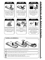
battery safety and installation
5
1. When inserting the batteries make sure the polarities are correct, that is, ‘+’ to ‘+’, ‘-’ to ‘-’.
2. Replace the batteries with the equivalent ‘AAA’ type.
3. Discard old batteries safely, following the battery safety guidelines.
battery installation
1
2
2
Remove cover of handset by lifting up the cover at the recess.
Insert batteries into handset as shown and replace cover.
Take care to fit your batteries
correctly, observing the plus
‘+’ and minus ‘-’ marks on
the battery and appliance.
Incorrect fitting can cause
leakage, or in extreme
cases, fire or explosion.
always
Replace the whole set of
batteries at one time, taking
care not to mix old and new
batteries of different types,
since this can result in
leakage, or in extreme
cases, fire or explosion.
always
Store unused batteries in
their packaging and away
from metal objects which
may cause a short circuit
resulting in leakage, or in
extreme cases, fire or
explosion.
+
-
+
-
+
-
+
-
always
Remove dead batteries from
equipment, and all batteries
from equipment that is to be
left for long periods of time
without any use. Otherwise
the batteries may leak and
cause damage.
never!
Never dispose of batteries in
fire as this can cause an
explosion.
Respect the environment -
always dispose of batteries in
an environmentally friendly
manner.
never!
Never attempt to recharge
ordinary batteries, either in a
charger or by applying heat to
them. They may leak, cause fire
or even explode. Rechargeable
NiCAD batteries and
chargers can be purchased
from any good High Street
electrical retailer.
CHARGE
+
-
1

aerial and VCR installation
6
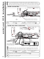
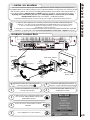
aerial connection
R
L
S
C
AUDIO LINE OUT
LR
AV1
AV2
2 X 12W 8
RF OUT
SERIAL PORT
LINE
C.1
C.2
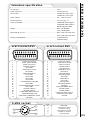
aerial and VCR connection
Connect VCR ‘out’ to your television’s RF socket ‘in’ marked
3
LR
AV1
AV2
RF OUT
SERIAL PORT
LINE
C.1
C.2
R
L
S
C
AUDIO LINE OUT
2 X 12W 8
Scart leads are an optional extra
*
4
IMPORTANT NOTE: When you connect your VCR to your television, the Audio Visual setting
has to be set correctly to ensure best picture quality -
see AV Setup section on page 32
1
2
3
Video Cassette Recorder
Connect aerial (RF) ‘link lead’ to
VCR RF ‘in’.
2
Connect aerial (RF) lead to digital ‘in’
marked
1
Connect aerial (RF) ‘link lead’ to
TV analogue ‘in’ marked
2
Connect aerial (RF) lead to digital ‘in’
marked
1
4
1
2
It is recommended that the RF (aerial) leads which connects external equipment to your TV -
and the actual aerial lead itself - should be of the highest quality. This will reduce interferance
and produce better picture quality and recordings. You can consult your dealer on this matter.
Note: The digital ‘link lead’ is the piece of
equipment with two ‘blocks’ near the end.
Note: The digital ‘link lead’ is
the piece of equipment with
two ‘blocks’ near the end.

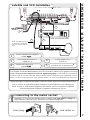
connecting to the mains socket
aerial, satellite, and VCR installation
7
Super-VHS video equipment should be connected to the AV1 scart socket located at the
rear of your TV. A dedicated program number may be assigned to AV1, allowing you
easier access to view external equipment broadcasts. How to assign an AV signal to
dedicated program numbers is explained on pages 20 and 21.
satellite and VCR installation
Connect aerial (RF) ‘link lead’ to
satellite RF ‘in’.
Connect VCR ‘out’ to TV ‘in’
marked
2
4
AV1
AV2
RF OUT
SERIAL PORT
LINE
C.1
C.2
R
L
S
C
AUDIO LINE OUT
2 X 12W 8
Scart leads are an optional extra
*
Important - If you have not already done so, please read television safety on
page 4 before connecting your television and external equipment.
insert plug...
...and switch on
5
*A scart lead should be fitted between your TV and VCR to enhance your picture and sound
quality. They are also rquired to record digital programs. Scart leads are essential if
you have a stereo TV and VCR and wish to obtain stereo sound from your equipment. These
leads can be purchased from your Hitachi dealer or any good High Street electrical
1
2
3
4
satellite decoder
Video Cassette Recorder
Connect aerial (RF) lead to digital ‘in’
marked
1
5
Connect satellite ‘out’ to
VCR RF ‘in’.
3
Note: The digital ‘link lead’
is the piece of equipment
with two ‘blocks’ near the
end.

television control panel
8
This will be lit when
your TV is on and when in
standby mode. It will flash
when a function
from your remote control
is being sent to the TV, or
the modem is in use.
When the TV is placed in
‘active’ standby mode or
recording events, the
colour will be orange (see
pages 20 and 41).
This is for
reading commands
sent from your remote
control handset.
Use this to switch
your TV on and off (when
switched off by using this
button your TV consumes no
power - unlike when in
standby mode).
To use the controls push the door in and release.
These sockets are
for use with external
equipment - see page 9.
This socket is for
use with external
equipment - see page 9.
Used with
headphones (3.5mm
stereo jack plug required).
Used to access your
on screen MAIN MENU for
TV features adjustment.
Used to change the TV
channel up ‘+’ or down ‘-’ (or
cursor up and down when using On
Screen Display menus).
Used to increase ‘+’, or
decrease ‘-’ your TV's sound (or
cursor right and left when in On
Screen Display menus).
on/off button
TV mode light
infra-red lens
television controls door panel
headphone socket
S-VHS sockets
audio/video sockets
volume buttons
program buttons
menu button

camcorder and computer connection
9
To use headphones with
your TV insert the headphone
jack plug (3.5mm) into the
corresponding socket.
(see sound mode on page 27)
Use this socket, along with
audio in right to obtain sound
from your external equipment
through your TV’s speakers.
Use this socket with an
S-VHS or Hi8 camera to view
your recordings.
Use this in conjunction
with a standard 8mm camera to
see the picture from your
equipment.
Use this socket, along with
audio in left to obtain sound from
your external equipment through
your TV’s speakers.
camcorder
Connecting a camcorder
to your TV is easy. First, identify
the type of camcorder and its
connecting sockets. If it is a
standard 8mm type camera then
this is likely to have 'RCA' type
sockets. If you have a S-VHS or
Hi8 camera you may have a S-
VHS socket. Open the front
control panel door and connect
your equipment as detailed here.
Switch your TV on and press the
TV/AV button on your
handset until AV3 is displayed on
your TV screen. Now begin
playback operation of your
equipment. Alternatively, you
could allocate an individual
channel number for your
camcorder equipment - see
signal source entry on
page 20.
connecting to the mains socket
Important - If you have not already done so, please read television safety on
page 4 before connecting your television and external equipment.
headphone connection
S-VHS socket
audio ‘in’ right
audio ‘in’ left
video ‘in’
If digital video broadcasting equipment, computer equipment or video games are to be
connected to this TV, use the AV2 located on the rear of your TV for RGB input.
PLEASE NOTE: Prolonged use of computer equipment or games on this TV may cause permanent
damage to your picture tube. To avoid such damage, reduce the brightness and contrast to an
acceptable level and limit the duration of use of computer equipment.
Before connecting external
equipment, please consult
AV setup on page 32.

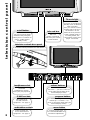
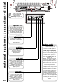
external equipment connection - digital
10
AV1
AV2
RF OUT
SERIAL PORT
LINE
C.1
C.2
R
L
S
C
AUDIO LINE OUT
LR
2 X 12W 8
RF OUT
SERIAL PORT
LINE
C.1
C.2
digital ‘RF OUT’
This should be permanently
connected directly to the ‘link
lead’, which should be either
connected to external equipment
or directly to the RF aerial
socket (see opposite page).
digital ‘RF IN’
This socket should be
permanently connected to
your RF source - i.e your
aerial antenna.
serial port
This slot is to be used to
accommodate future digital
services (such as home
banking), software upgrades
and additional external
equipment connected to your
digital system.
card slot 2
This serial port will connect
directly to external
equipment in future
developments.
To take advantage of
the modem and future
services you will require a
modem lead
(431A plug to RJ11 plug)
and a dual outlet adaptor to
connect to your existing phone
socket. Details on how to
connect the equipment are
given in modem set up
on page 42.
NOTE: Your Hitachi TV with
modem has what is called a
Ringer Equivalence Number
(REN). This is shown on a label
fitted on the back cover near
the scart sockets. With
external equipment this
modem socket is connected to
a telephone line. It is possible
that along with your modem
there will be other
communications equipment
(each of which will have its
own REN number)connected
to the telephone line. Each
piece of connected equipment
should remain operational
providing the total sum of all
the REN numbers is no greater
than 4.
modem socket
This slot is to be used to
accommodate future digital
services (such as home
banking), software upgrades
and additional external
equipment connected to your
digital system.
card slot 1
Before connecting
external equipment,
please consult
AV setup on page 32.

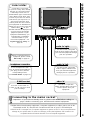
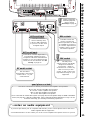
external equipment connection - analogue
11
AV1
AV2
RF OUT
SERIAL PORT
LINE
C.1
C.2
R
L
S
C
AUDIO LINE OUT
LR
2 X 12W 8
Use this socket to
connect ordinary VHS,
S-VHS or Hi8 equipment
to your TV. It is also used
for digital output.
The 18V power
output socket is specifically
designed for HITACHI
accessories - under no
circumstances connect any
other accessory to this
socket as this could cause
irreparable damage to your
equipment.
Use these connections to attach your leads to the amplifiers and speakers:
S is for the surround amplifier and speakers
C is for the centre amplifier and speaker
R is for the right amplifier and speaker
L is for the left amplifier and speaker
Once connected de-activate 3DS system (see page 28) and set Speaker Setup to WIDE or NORMAL
mode (see page 30) - with this configuration, using 5 external speakers full Dolby Pro Logic can be
achieved enhancing your viewing and listening experience.
R
L
LR
S
C
AUDIO LINE OUT
AV1
AV2
2 X 12W 8
Use this to connect digital video
broadcasting equipment, home
computers and home entertainment
systems to your TV. Output from this
connector can be selected. See AV
setup on page 32.
This should be
permanently connected to
an RF source - i.e your
aerial antenna.
The DIN sockets are
used to connect two
external speakers for which
no amplifier is necessary.
R is for the right external
speaker, and L is for the
left external speaker.
...notes on audio equipment
If you have purchased your TV complete with Hitachi’s power console please refer to the Users
Guide supplied with the equipment.
Your HITACHI dealer can also advise you on the correct amplifier and speaker choice for your TV.
18V socket
AV2 scart input
AV1 scart input
RF aerial socket
quad phono sockets
DIN sockets
Before connecting
external equipment,
please consult
AV setup on page 32.

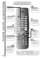
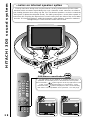
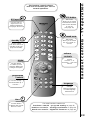
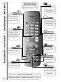
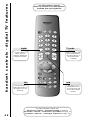
handset controls - program tuning
12
This button is
used to return to the
previous menu you
were viewing, or to
cancel a selection.
Press this
button to leave the
menu you are on and
return to normal TV
operation.
This button is
used to enter the
main menu. This is
where your TV’s
features options are
displayed.
This button is
used to confirm a
highlighted selection
Use this button
to move the menu
selection box right.
Use this button
to move the menu
selection box left.
Use this button
to move the menu
selection box up.
Use this button
to move the menu
selection box down.
cursor down
cursor up
go back
accept
menu
exit
cursor right
The handset controls shown below
are used when programming your TV and
to adjust the sound and picture features.
cursor left
Use these
buttons to enter
frequency values.
digits 0 to 9
For other handset controls see
handset controls - television operation on page 33
handset controls - analogue teletext on page 34
handset controls - digital TV features on page 46

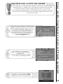
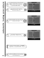
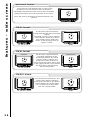
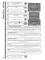
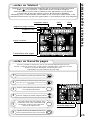
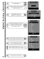
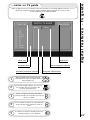
automatic tuning procedure and Digital program swap
13
important note on VCR and satellite
Do not switch your TV on until all external equipment is connected. If you have a Video
Cassette Recorder or a Satellite receiver connected to this TV please ensure that they
are switched on before automatic tuning begins. In the case of a VCR, insert a
pre-recorded tape and begin playback of your equipment. With a Satellite receiver select
Sky News. These measures ensure that all your external equipment is tuned in during
the autotune procedure.
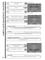
Your TV will now search through the digital
frequencies. It stores them in the DIGITAL
ORGANISER as it finds each digital program.
3
To make your program tuning easier, HITACHI have
installed an automatic tuning procedure to find the
digital and analogue programs. Switch your TV on.
If you are satisfied all external equipment has been
connected, you can begin AUTOTUNE. It is
recommended that both analogue and digital are
stored at the same time, so press button ‘1’ on
your handset and AUTOTUNE will begin
- firstly the analogue search.
1
Your TV will now search through the
analogue frequencies, listing them into the
following order -
0.Video 1.BBC1, 2.BBC2, 3.ITV 4.CH4/S4C,
5.CH5 (subject to availability) 6.Satellite.
2

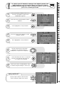
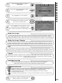
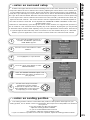
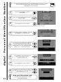
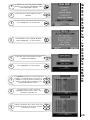
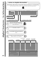
automatic tuning procedure
14
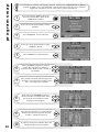
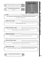
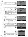
To finish the installation process and return to
normal TV operation press the menu button
on your handset twice.
8
Once program of choice has been
highlighted, select OK to confirm - the
selection bar will turn red.
5
To organise programs you must swap their
positions. Use the up/down cursor keys to
highlight a program whose position you
want to change (in the example on the
right it is the BBC1 service).
4
Using the up/down cursor keys move your
selected program to the program number
you wish it to occupy.
6
Press OK to confirm your new
program position - repeat if necessary.
7
Programs can also be deleted - see ‘Digital
Organiser - Program Delete’ on page 39.
Use
to choose, OK to select service
Re-order service list or delete services.
▲
▼
Use
to choose, OK to select service
Re-order service list or delete services.
▲
▼
Use
to choose, OK to select service
Re-order service list or delete services.
▲
▼

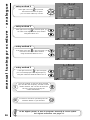
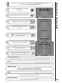
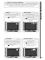
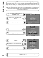
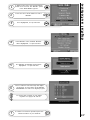
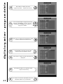
manual tuning procedure - analogue
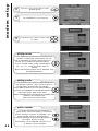
15
Press and hold the MENU button for 5
seconds. The INSTALL option in the
MAIN MENU appears.
Press the cursor down button to select
INSTALL .
Once highlighted, accept selection.
Press the cursor down button to select
MANUAL SETUP.
Once highlighted, accept selection.
Once selected press OK to accept the
selection. The selection bar turns red
- it is ready to be changed.
Use the cursor keys to move the
selection bar over the program
FREQUENCY required to be adjusted.
entry method 1
The first option will be to fine tune the
chosen frequency either up or down.
1
2
3
4
5
6
7
Select your choice of FREQUENCY entry
method using the left/right cursor keys.
8
To switch your TV between analogue and digital systems, the
digital handset on your handset has to be pressed. Before
starting manual tuning procedure (analogue) please ensure that
your TV is in analogue mode.

manual tuning procedure - analogue
16
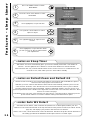
Once the method of entry has been decided
upon and the new frequency, channel or band
number entered, this can then be stored in
the TV's memory by pressing the
confirmation button.
To return to normal TV operation press the
television button on your handset.
entry method 2
If the right cursor key is pressed,
autosearch becomes an option
- you can search either up or down.
entry method 3
If the right cursor key is pressed again, you
can enter a two digit channel (CH) number
using the buttons 0-9.
entry method 4
If the right cursor key is pressed again, you
can enter a two digit S-Band number
using the handset buttons 0 to 9.
entry method 5
If the right cursor key is pressed again,
you can manually input a five digit frequency
using the numbered handset buttons 0 to 9.
9
10
-
-
-
In the digital system, to tune in programs manually is not an option.
For digital autotune see page 37.

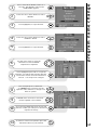
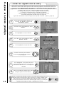
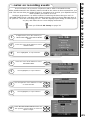
program name change
17
Press and hold the MENU button for 5
seconds. The INSTALL option in the
MAIN MENU appears.
Press the cursor down button to select
INSTALL.
Once highlighted, accept selection.
Press the cursor down button to select
MANUAL SETUP.
Once highlighted, accept selection.
Once highlighted press OK to accept the
selection. You will see the selection bar turn
red and the chosen character will flash on
and off - it is ready to be changed.
You can input up to 5 characters
- to change each character use the
up/down cursor buttons to change each
letter or symbol
To move from character to character
use the right/left cursor buttons.
Once the new NAME has been chosen and
entered, confirm your entry to be stored and
repeat if necessary.
To return to normal TV operation press the
television button on your handset.
Use the cursor keys to move the
selection bar over the NAME
required to be adjusted.
1
2
3
4
5
6
7
8
9
10
11

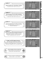
program swap
18
Press and hold the MENU button for 5
seconds. The INSTALL option in the
MAIN MENU appears.
Press the cursor down button to select
INSTALL.
Once highlighted, accept selection.
Press the cursor down button to select
MANUAL SETUP.
Once highlighted, accept selection.
Once number has been selected press the
OK button. The selection bar wil then turn
red - it is ready to be swapped.
Now select your second program to
swap. Move the red selection bar using
the up/down cursor buttons of the
program to be swapped.
Once this has been done, accept selection
and the two chosen programs will swap
position - repeat if necessary.
To return to normal TV operation press the
television button on your handset.
Select your first program to swap by
moving the selection bar using the
up/down cursor buttons over a channels
PR number.
1
2
3
4
5
6
7
8
9
10
It is advisable to organise your viewing channels at this point - Signal Source Entry
on page 20 allows you to give individual channels their own signal source for external
equipment connection such as camcorders, games machines etc.

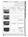
picture controls
19
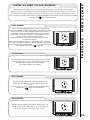
Press the MENU button to obtain
MAIN MENU.
The MAIN MENU highlights the PICTURE
option automatically - press OK to select.
1
2
Noise Reduction
Helps reduce the noise interference visible on your television, especially in weaker signal reception areas.
White Point
NORMAL - gives an equally balanced spectrum of colour.
COOL - exaggerates the blue tones of your television picture.
WARM - this exaggerates the red tones of your television picture.
CTI
Colour Transient Improvement - this control lets you improve the clarity of your televisions colour edges.
VM
Velocity Modulator - this increases or decreases the sharpness of your televisions picture so it appears less blurred
,especially in the left and right edges of the screen.
Select the picture control to be adjusted by
using the up / down cursor buttons.
Once highlighted, adjust the chosen
controls by pressing the right / left cursor
buttons.
3
4
To select MORE options use the up/down
buttons to highlight selection and then
press OK to confirm.
5
Select the picture control to be adjusted by
using the up/down cursor buttons.
Once highlighted, adjust the chosen controls
by pressing the right/left cursor buttons (for
explanation see below)
6
7
The values changed will remain until they are
next altered, press the TV button on your
handset to return to normal TV operation.
8
For picture and sound values, moving the cursor left will decrease values, whilst
moving the cursor right will increase values.
Black Stretch
This control turns all dark grey pixels black.

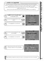
signal source entry
20
Press and hold the MENU button for 5
seconds. The INSTALL option in the
MAIN MENU appears.
Press the cursor down button to select
INSTALL.
Once highlighted, accept selection.
Press the cursor down button to select
MANUAL SETUP.
Once highlighted, accept selection.
Use the cursor keys to move the
selection bar over the AV required
to be adjusted.
Select your method of signal source entry
using the up/down cursor buttons.
Once highlighted, accept the selection to
change the signal source and you will see
the selection bar turn red - it is ready to be
changed.
1
2
3
4
5
6
7
8
NOTE: To ensure that analogue events are recorded when placing your TV in
analogue mode it is necessary to place your TV in an ‘active’ standby mode.
This is done by pressing the standby button followed within a second by
pressing the AV button. This ensures that the digital circuitry your analogue
signal passes through is ‘awake’, enabling you to record.
then
...notes on signal source entry
Each piece of external equipment connected to your TV must have its own input socket. It
would also be easier, and more organised, if the external equipment connected also had its own
program number. Signal Source entry allows us to tell the allocated program what
equipment is connected to which socket. This would make the switching between normal TV
operation and the use of connected equipment much smoother.
For example, if you want to connect a games machine to your TV -
1. connect to socket AV2 via a scart lead (see page 11)
2. give your games machine an empty channel number of its own
3. if desired change this channel name (see page 17)
4. give this channel the correct AV signal source (in this case AV2 - option 2, page 26)
Page is loading ...
Page is loading ...
Page is loading ...
Page is loading ...
Page is loading ...
Page is loading ...
Page is loading ...
Page is loading ...
Page is loading ...
Page is loading ...
Page is loading ...
Page is loading ...
Page is loading ...
Page is loading ...
Page is loading ...
Page is loading ...
Page is loading ...
Page is loading ...
Page is loading ...
Page is loading ...
Page is loading ...
Page is loading ...
Page is loading ...
Page is loading ...
Page is loading ...
Page is loading ...
Page is loading ...
Page is loading ...
Page is loading ...
Page is loading ...
Page is loading ...
Page is loading ...
Page is loading ...
Page is loading ...
Page is loading ...
Page is loading ...
-
 1
1
-
 2
2
-
 3
3
-
 4
4
-
 5
5
-
 6
6
-
 7
7
-
 8
8
-
 9
9
-
 10
10
-
 11
11
-
 12
12
-
 13
13
-
 14
14
-
 15
15
-
 16
16
-
 17
17
-
 18
18
-
 19
19
-
 20
20
-
 21
21
-
 22
22
-
 23
23
-
 24
24
-
 25
25
-
 26
26
-
 27
27
-
 28
28
-
 29
29
-
 30
30
-
 31
31
-
 32
32
-
 33
33
-
 34
34
-
 35
35
-
 36
36
-
 37
37
-
 38
38
-
 39
39
-
 40
40
-
 41
41
-
 42
42
-
 43
43
-
 44
44
-
 45
45
-
 46
46
-
 47
47
-
 48
48
-
 49
49
-
 50
50
-
 51
51
-
 52
52
-
 53
53
-
 54
54
-
 55
55
-
 56
56


Ask a question and I''ll find the answer in the document
Finding information in a document is now easier with AI
Related papers
-
Hitachi C28W510SN User manual
-
-
-
-
-
-
-
-
Hitachi C32W1TN User manual
-
Hitachi 42PD3000 User manual
Other documents
-
Technicolor - Thomson T7021e User manual
-
-
-
-
Panasonic TX22LT2 Operating instructions
-
Sony KV-32DX30U User manual
-
-
-
-
Beko 15LB250MID User manual