5- Accessories
PARAMETERS TRANSFER
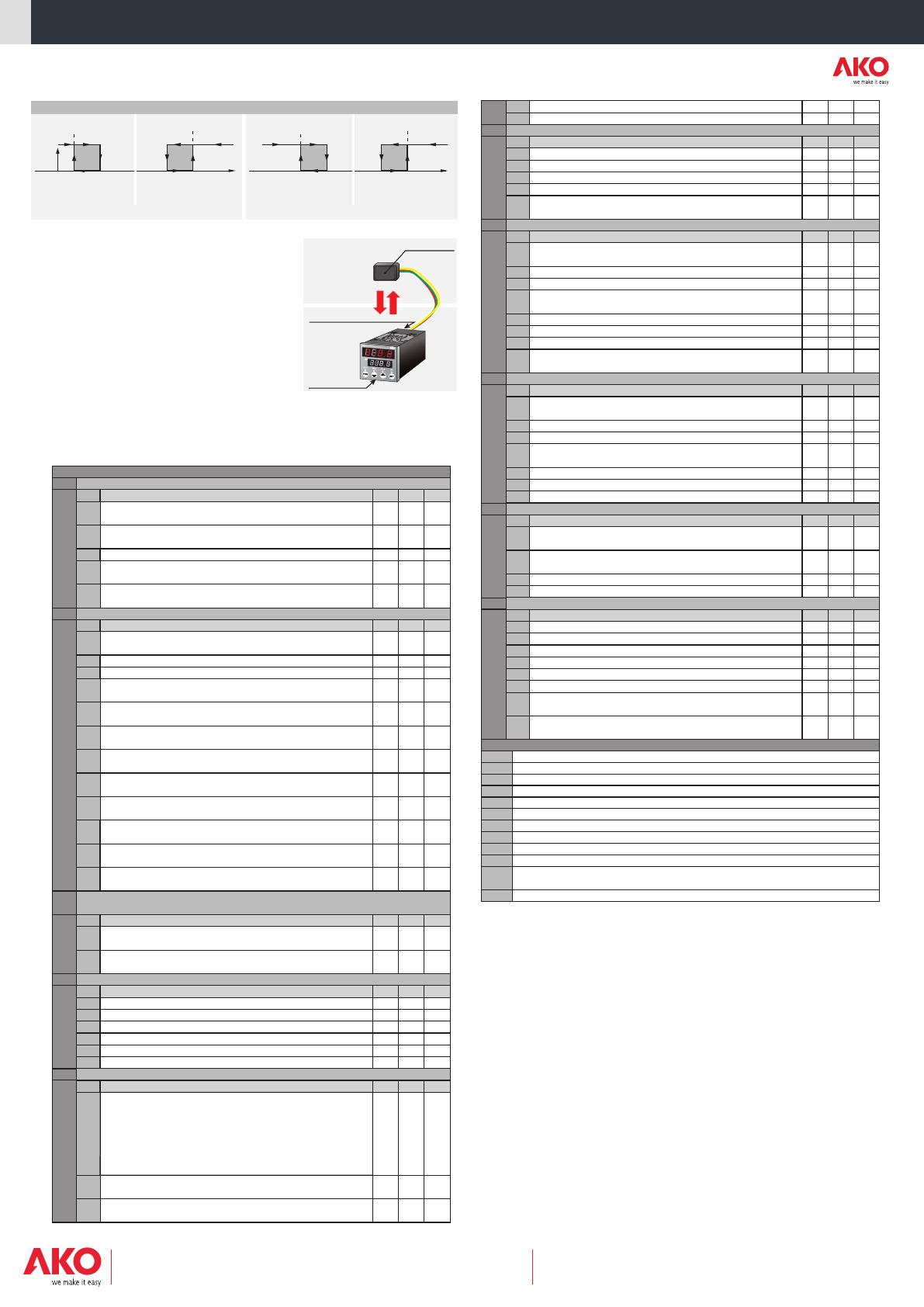
AKO-14918 portable server, with no power supply, in which
parameters programmed in a powered controller can be copied by
transfer. Parameters can be transferred again from the server to
other identical powered controllers.
6- Maintenance and Warnings
Clean the controller surface with a soft cloth and soap and water.
Do not use abrasive detergents, petrol, alcohol or solvents.
The use of the unit without observing the manufacturer's
instructions may alter its safety qualification. To ensure correct
operation of the apparatus, only probes supplied by AKO should be
used.
7- Parameters and messages
Values in the Def. column are factory-set.
AKO-14918
Transfer
Power supply
Programming
Level 2
Level 2
PAr
Ct
PAS1
CAd
CtHA
CtLA
Ctdy
CtUA
Ctin
Ctou
PdE
Ptr
CtEr
CtLC
General Parameters
CT Current transformer parameters (If CtEn=1 in CT module)
Level 3
Level 3
Description
Description
Values
Values
Min.
Min.
Def.
Def.
Max.
Max.
Password to parameters and information
Address for units with communication
Max for Alarm CT
Min for Alarm CT
Alarm CT delay from the moment at which it should enabled
Current load value (display)
Primary current value CT transformer
Secondary current value CT transformer (0=0,05A)
Initial parameters
(1=YES, configure to “Def” and exit programming)
Parameters transfer
(0=Disabled) (1=Send) (2=Receive)
Output CONTROL 1 status in case of CT alarm:
(0=OFF) (1=No change)
CT alarm memory
(0=Without memory) (1=With memory)
0
0
0,0
0,0
0
0,0
0
0
0
0
0
0
0
2
0
100,0
0,0
0
Value
25
0
0
0
0
1
1
999
254
100,0
100,0
250
100,0
999
999
250
1
2
1
1
(A)
(A)
(min.)
(A)
(A)
(A)
Level 2
Level 2
Level 2
ALr1
ALr2
Pld
GAin
AHt1
AHt2
Adl1
Adl2
ALt1
ALt2
AdE1
AdE2
Ado1
Ado2
ti
td
toUt
IdY
USI1
AtEn
tAL1
tAL2
ACo1
AtA
ACo2
Alarm 1 Parameters
Alarm 2 Parameters (If Clo=0, 4, R1=Alarm 2)
PID Parameters (only if rEG=0)
Level 3
Level 3
Level 3
Description
Description
Description
Values
Values
Values
Min.
Min.
Min.
Def.
Def.
Def.
Max.
Max.
Max.
Gain (see item 4.1)
Max for Alarm 1
Max for Alarm 2
Alarm 1 differential
Alarm 2 differential
Min for Alarm 1
Min for Alarm 2
Alarm 1 delay from the moment at which it should enabled
Alarm 2 delay from the moment at which it should enabled
Alarm 1 delay at start-up
Alarm 2 delay at start-up
Overall time (see item 4.1)
Derivative time (see item 4.1)
Cycle Control time
Digital input enabling delay
Set point SP 1 variation if CdIn=1
AT key blocking
(0=Yes, blocked) (1=No, unblocked)
Alarm 1 type
(0=Max) (1=Min) (2=Max+Min)
Alarm 2 type
(0=Max) (1=Min) (2=Max+Min)
Alarm 1 configuration (0=Absolute)
(1=Relative to set point SP1) (2=Relative to set point SP2)
Optional cancellation of output alarms by pressing once a key.
(0=Allows to cancel the output alarms) (1=Not allows to cancel the output alarms)
Alarm 2 configuration (0=Absolute)
(1=Relative to set point SP1) (2=Relative to set point SP2)
0
-99,9
-99,9
1,0
1,0
-99,9
-99,9
0
0
0
0
0
1,0
0
-99,9
0
0
0
0
0
0
50
999,9
999,9
1,0
1,0
-99,9
-99,9
0
0
0
100
25
2,0
0
0,0
0
0
0
0
0
0
100
2500
2500
20,0
20,0
2500
2500
250
250
250
999
999
100,0
250
2500
1
2
2
2
1
2
(%)
(sec.)
(sec.)
(sec.)
(ºC/ºF/mA)
(ºC/ºF/mA)
(ºC/ºF/mA)
(ºC/ºF/mA)
(ºC/ºF/mA)
(ºC/ºF/mA)
(ºC/ºF/mA)
(min.)
(min.)
(min.)
(min.)
(sec.)
MESSAGES
Flashing with temperature - Sensor temperature exceeds the parameter programmed in AHt1
Flashing with temperature - Sensor temperature exceeds the parameter programmed in AHt2
Flashing with temperature - Sensor temperature is lower than the parameter programmed in ALt1
Flashing with temperature - Sensor temperature is lower than the parameter programmed in ALt2
Flashing with temperature - Active digital input
Stopped controller if CdIn=2 and digital input enabled
Sensor failure (Open circuit, crossed, temperature out of range)
EEPROM memory failure
RAM memory failure
Password request to enter programming parameters
Incorrect resolution - See rES parameter
Flashing with temperature - The load intensity circulating through the CT current transformer exceeds
the programmed parameter in CtHA or is lower than the programmed parameter in CtLA
AH1
AH2
AL1
AL2
EAL
StoP
E1
EE
rA
PAS
----
ACt
VALUE
OFF
AL1 AL2 AL2
VALUE
Alarm 2 Operation
ACo1 is the alarm 1 configuration parameter ACo2 is the alarm 2 configuration parameter
tAL1=0 (Max.) tAL2=0 (Max.)tAL2=1 (Min)
SP2+ALt2+Adi2SP2+ALt1+Adi1 SP2+AHt2+Adi2SP2+AHt1+Adi1 SP2+AHt2SP2+AHt1
SP1+ALt2+Adi2SP1+ALt1+Adi1 SP1+AHt2+Adi2SP1+AHt1+Adi1 SP1+AHt2SP1+AHt1
ALt2+Adi2ALt1+Adi1 AHt2+Adi2AHt1+Adi1 AHt2AHt21
SP2+ALt2SP2+ALt1
SP1+ALt2SP1+ALt1
ALt2ALt1 Si ACo2 = 0Si ACo1 = 0
Si ACo2 = 1Si ACo1 = 1
Si ACo2 = 2Si ACo1 = 2
StartStart StartStart StopStop StopStop
Alarm 1 Operation
ON
AL1
tAL1=1 (Min)
8- Technical data
Range according to type of sensor configured:
Pt 100.............................................................................-99,9 ºC to 850,0 ºC (-148 ºF to 1562 ºF)
J Thermocouple.................................................................-99,9 ºC to 800,0 ºC (-148 ºF to 1472 ºF)
K Thermocouple.................................................................-99,9 ºC to 1370 ºC (-148 ºF to 2498 ºF)
4-20 mA.......................................................................................4 mA = 0% to 20 mA = 100%
Set Point 1 range...................................................................................................-99.9 to 2500
Set Point 2 range...................................................................................................-99.9 to 2500
Resolution, Set Point and differential ........................................0,1 or 1 configurable by parameter rES
Accuracy...........................................................................±0,25 % (Pt100, TcJ, TcK); ±1,5% (mA)
R1/OUT relay: CONTROL 2 or ALARM 1 or 2 (configurable by param. CIo) .....SPST-NO, 6A, 250V, cosj=1
R2/AL relay: CONTROL 1 or ALARM 1 (configurable by param. CIo)...................SPDT, 5A, 250V, cosj=1
R3 relay: CONTROL 2 (with Relay 3 module) (configurable by param. CIo) ..........SPDT, 5A, 250V, cosj=1
Maximum input power .......................................................................................................3 VA
Working ambient temperature.................................................................................. 0 ºC to 55 ºC
Storage ambient temperature ................................................................................-30 ºC to 70 ºC
Installation category.........................................................................II under EN 61010-1 standard
Pollution degree ..............................................................................II under EN 61010-1 standard
Double insulation between the power supply, the secondary circuit and the relay output.
351540502 REV.02 2009
AKO ELECTROMECÀNICA, S.A.L.
We reserve the right to supply materials that might vary slightly to those described in our
Technical Sheets. Updated information is available on our website: www.ako.com
Av. Roquetes, 30-38 | 08812 Sant Pere de Ribes | Barcelona | España
Apartado (P.O. Box), 5 | 08800 Vilanova i la Geltrú | Barcelona | España
www.ako.com
Temperature display mode: (0 = Integers in ºC) (1 = One decimal in ºC)
(2 = Integers in ºF) (3 = One decimal in ºF) (4 = Integers in mA) (5 = One decimal in mA)
(ºC/ºF/mA)
-20,0
-99,9
-99,9
LL1
LL2
-99,9
0
0
0
0
0
0
-99,9
0,0
100,0
0
999,9
999,9
-99,9
0
0
1
1
0
1
-99,9
20,0
2500
2500
2500
2500
HL1
1
1
1
1
2
5
HL2
(ºC/ºF/mA)
(ºC/ºF/mA)
(ºC/ºF/mA)
(ºC/ºF/mA)
0
0
3
AnCF
Description
4-20 mA or onfiguration parameters
(only if CIo=0, 1, 2) and 4-20 mA / 0-10 V module
converter repeater c
Values
Min. Def. Max.
Values
Min. Def. Max.
Level 2
CFG
Configuration Parameters
Level 3
Description
Level 1
Menus and Description
Level 2
SPCF
Set Point parameters
Level 3
Description
CAn
HES
LES
HL1
LL1
bES
rEG
HC1
HC2
o2C
rES
LL2
HL2
Sensor calibration (Offset)
Maximum scale value for the sensor type in mA (Only if PbS=3)
Minimum scale value for sensor type in mA (Only if PbS=3)
Set point upper limit
(It cannot be set above this value)
Set point lower limit
(It cannot be set below this value)
Sensor type selection
(0=Pt100) (1=TcJ) (2=TcK) (3=4-20mA)
Blocking the scale between HES and LES (Only if PbS=3)
(0=Free scale) (1=Blocked scale)
Type of control: (0=PID for CONTROL 1) (1=ON/OFF for CONTROL 1)
(CONTROL 2 always ON/OFF, only if Clo=1,2,3)
Type of operation in CONTROL 1
(0=Direct, cold)(1= Reverse, heat)
Type of operation in CONTROL 2
(0=Direct, cold)(1= Reverse, heat) (Only if Clo=1,2,3)
CONTROL 1, CONTROL 2 Ratio Type (Only if CONTROL 2 CIo=1, 2, 3)
(0 = Two independent stages) (1 = Two related stages) (2 = Neutral Zone)
Set Point 2 lower limit
(It cannot be set below this value) (only CONTROL 2 CIo=1, 2, 3)
Set Point 2 upper limit
(It cannot be set above this value) (only CONTROL 2 CIo=1, 2, 3)
PbS
Level 2
Level 2
inPt
onoF
diF1
diF2
ton1
ton2
toF1
toF2
Cdln
IPo
Clo
Er1
Er2
CtEn
ON/OFF Configuration Parameters (only if rEG=1) or (Clo=1,2,3)
Level 3
Level 3
Description
Digital INPUT/OUTPUT (I/O, 5-, 6+) and Relays R1, R2, R3 configuration
Description
Values
Values
Min.
Min.
Def.
Def.
Max.
Max.
CONTROL 1 Differential (Hysteresis) (only if rEG=1)
CONTROL 2 Differential (Hysteresis) (only CONTROL 2 CIo=1, 2, 3)
Minimum CONTROL 1 time in ON (only if rEG=1)
Minimum CONTROL 1 time in OFF (only if rEG=1)
Minimum CONTROL 2 time in ON (only CONTROL 2 CIo=1, 2, 3)
Minimum CONTROL 2 time in OFF (only CONTROL 2 CIo=1, 2, 3)
Maximum output value scale for 20 mA / 10 V
(If PbS=0,1,2,) (If PbS=3, AHES=HES)
Minimum output value scale for 4 mA / 0 V
(If PbS=0,1,2,) (If PbS=3, ALES=HLS)
Digital input configuration if Clo=2,3,4
(0=External alarm) (1=Variation in Set point) (2=Start-Stop)
Digital input status inversion:
(0=Closed contact) (1=Open contact)
Digital Input / Output and R1, R2, R3 relays
(0= Digital Output SSR CONTROL 1, R1=ALARM 2, R2=ALARM 1) *
(1= Digital Output SSR CONTROL 1, R1=CONTROL 2, R2=ALARM 1) *
(2= Digital Input, R1=ALARM 1, R2=CONTROL 1, R3= CONTROL 2) *
(3=Digital Input, MODULE 4-20 mA / 0-10 V CONTROL 1,
R1=CONTROL 2, R2=ALARM 1) (only with MODULE 4-20 mA / 0-10 V)
(4=Digital Input, MODULE 4-20 mA / 0-10 V CONTROL 1,
R1=ALARM 2, R2=ALARM 1) (only with MODULE 4-20 mA / 0-10 V)
CONTROL 1 status with faulty sensor:
(0=OFF) (1=ON)
CONTROL 1 status with faulty sensor: (Only if Clo=1,2,3)
(0=OFF) (1=ON)
Enable / Disable CT alarm
(0=Disabled) (1=Enabled)
-50,0
-50,0
0
0
0
0
-99,9
-99,9
0
0
0
1,0
1,0
0
0
0
0
200,0
-50,0
0
0
0
50,0
50,0
250
250
250
250
2500
2500
2
1
4
(ºC/ºF/mA)
(ºC/ºF/mA)
(sec.)
(sec.)
(sec.)
(sec.)
0
0
0
0
0
1
1
1
1
Level 2
Level 3
AHES
AHES
Values
Min. Def. Max.
* In the 4-20 mA / 0-10 V module, it only acts as a repeater/converter.


