Page is loading ...

www.sulzer.com
81307033G (06/2016)
Control Panel Type ABS CP 116/216
EN User Guide SW 1.33
ON ON ON ON ON ON

81307033G
2
Control panel type ABS CP 116/216, User guide SW 1.33
EN
Copyright © 2016 Sulzer. All rights reserved.
This manual, as well as the software described in it, is furnished under license and may
be used or copied only in accordance with the terms of such license. The content of this
manual is furnished for informational use only, is subject to change without notice, and
should not be construed as a commitment by Sulzer. Sulzer assumes no responsibility or
liability for any errors or inaccuracies that may appear in this book.
Except as permitted by such license, no part of this publication may be reproduced, stored
in a retrieval system, or transmitted, in any form or by any means, electronic, mechanical,
recording, or otherwise, without the prior written permission of Sulzer.
Sulzer reserves the right to alter specications due to technical developments.

3
Control panel type ABS CP 116/216, User guide SW 1.33
81307033G
EN
CONTENTS
About this guide, audience and concepts 5
1 Overview of functions and usage 7
2 Settings 11
2.1 Select language ............................................................. 11
2.2 Overview of settings ......................................................... 11
2.3 System settings ..............................................................12
2.4 Pump pit settings ............................................................. 13
2.5 Pump settings ...............................................................16
2.6 Common settings for pump 1 and pump 2 .........................................18
2.7 Analogue logging .............................................................19
2.8 Settings for trend curves .......................................................19
2.9 Settings for analogue inputs ....................................................20
2.10 Settings for digital inputs .......................................................21
2.11 Settings for digital outputs (alarm relays) ..........................................21
2.12 Settings for pulse channel ......................................................22
2.13 Communication settings .......................................................22
3 Daily operation 25
3.1 Manual control .............................................................. 25
3.2 Alarm list .................................................................. 25
3.3 Show status ................................................................ 26
3.4 Trend curves ................................................................27
4. Appendix 29
4.1 Pumpcapaictyandin/outowofthepit ........................................... 29
4.2 Pit shape ...................................................................30
4.3 Overowowcalculation ....................................................... 31
4.3.1 Howtocalculateoverowsbyusingconstantsandexponents .........................32
4.4 Pump alternation (only CP 216) ..................................................32
4.5 Communication ..............................................................33
4.5.1 Modem options .............................................................. 34
4.5.2 Serviceport(9-polsD-Subinthefront) ............................................35
4.5.3 Alarms .....................................................................35
4.6 AquaProg ...................................................................36
4.6.1 How to set up AquaProg .......................................................36
4.7 Crossreferencetable ..........................................................37
4.8 How to clean the unit ..........................................................37
5. Technical data and EMC compatibility 39
5.1 Technical data ...............................................................39
5.2 Built-in pressure sensor ........................................................39
5.3 Maximumload ...............................................................39

4
81307033G
EN

5
Control panel type ABS CP 116/216, User guide SW 1.33
81307033G
EN
ABOUT THIS GUIDE, AUDIENCE AND CONCEPTS
This guide describes the pump control panels CP 116 ⁄ 216. The difference be-
tween the two products is that CP 116 controls one pump whereas CP 216 can
control two pumps. CP 116 does not include any circuit breaker, whereas CP 216
includes a 3-pole circuit breaker for each pump.
Installation Guide There is a separate document Installation Guide that describes how to physically
install the control panel (printed document in the installation package, and also a
PDF on the CD).
Audience This guide is intended for system administrators and operators of control panel
CP 116 ⁄ 216.
Prerequisites This guide assumes that you already are acquainted with those pumps you are
set to control and the sensors connected to CP 116 ⁄ 216.
The system administrator must also know and decide on the following:
The control panel can either use an analogue level-sensor, which measures the
water level in the pit, for precise control over start and stop levels, or it can use
simple oat switches placed at start and stop levels.
Float switches can be used in addition to an analogue level-sensor, as a backup,
and as an additional alarm input.
An analogue level-sensor has several advantages over oat switches: it is more
robust (can not get stuck or be mechanically jammed); it is more accurate; it
is more exible (you can easily change the start and stop levels); you can get
readings of the water level in the pit, the inow, overow and the pump capacity;
you can optimise the pump performance in various ways, including exercising,
alternative stop levels, tariff control etcetera.
It is also possible to employ an alternative stop level, usually a lower level than
normal, that is effective once after a number of pump starts. This can be useful if
it is desirable to “completely” empty the pit once in a while.
You need to know if the pump(s) should be exercised in case of long idle periods.
If the installation has two pumps, you need to decide if the pumps should alter-
nate.
If the electricity has daily varying tariffs, you must know the times of high/low
tariffs.
You must know how overow will be measured: if it will be measured using both
an overow detector (to detect the start of the overow) and a level sensor (to
measure the actual ow), you must know the parameters (exponents and con-
stants) to be entered as settings so that the overow can be accurately meas-
ured by a calculation in CP 116 ⁄ 216.
You need to know which alarm class, A-alarm or B-alarm (see Glossary and
conventions on page 6), to assign each alarm.
Reading guide For installation, see the separate document Installation Guide, which covers both
CP 116 ⁄ 216 and CP 112 ⁄ 212. Before you make any settings, or use the control
panel, read Chapter 1 Overview of functions and usage; it describes the general
functionality and the meaning and usage of the controls on the panel.
The system administrator must ensure that all settings according to Chapter 2
Settings are suitable for your application. The default settings are listed in the
Installation Guide.
Most settings in Chapter 2 only apply to the system administrator, but the follow-
ing also apply to those who only operate the controller: language selection, date
and time settings, units, backlight timeout, buzzer, operator passcode, start/stop
levels.
Chapter 3 on page 25 covers the topics needed for the regular daily operation.

6
81307033G
About this guide, Audience and concepts
EN
Glossary and conventions To designate a menu item in a hierarchy, an angle bracket is used to separate
the levels. Example: Settings > System means the menu item you reach by rst
choosing the menu item Settings, which has a number of submenus, where you
choose the menu item System.
Text in blue indicates a hypertext link. If you read this document on a computer,
you can click on the item, which will take you to the link destination.
Pump exercising: Long idle periods in a corrosive contaminated environment are
not good for pumps. As a countermeasure, they can be “exercised” at regular
intervals, which will reduce corrosion and other detrimental effects.
Cos φ: Cosine of the phase angle φ between the motor current and the voltage.
Alarm class: The alarm class can be either A-alarm or B-alarm. A-alarms are
those that require immediate action, so operational staff in the eld should be
alerted regardless of the time of day. B-alarms are less important, but should be
taken care of during normal work hours.
Digital In means a signal that is either on or off (high or low), where high is any-
thing between 5 and 24 volts DC, and low is anything below 2 volts.
Digital Output means an alarm relay that may either be normally closed or nor-
mally open.
Analogue Inputs are for sensors, and these inputs sense current in the range
4–20 mA or 0–20 mA.

7
Control panel type ABS CP 116/216, User guide SW 1.33
81307033G
EN
1 OVERVIEW OF FUNCTIONS AND USAGE
CP 116 and CP 216 are control panels for one and two pumps respectively.
These units have the same functionality in terms of their capability to control
pumps and manage alarms — the only difference is that CP 216 is intended for
two pumps whereas CP 116 is intended for one pump.
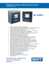
Figure 1-1 shows the panel, and describes the functions of the buttons and the
meaning of the indicator lamps. The six buttons to the right of the display are
used to navigate in menus and change settings, whereas the buttons to the left
of the display are used to control the pump mode and for manual control of the
pump.
25.0 l/s
Low capacity P2
2.50 m
5.3 l/s
12
5.8 A4.7 A
Figure 1-1 A green lamp at the very left indicates that the unit is powered (either battery
or mains). The red alarm indicator will blink whenever there is an unacknowledged alarm.
For each pump (P1 and P2), there is a button with which you can set the pump in either
Auto mode or blocked. An indicator lamp shows whether the pump is in Auto mode (green)
or manually blocked (yellow). Below that, there is a button (hand symbol) with which you
can control the pump manually.
You navigate the menus by the arrow buttons. Press either the Up or Down arrow button to
switch to the menu view. You conrm an operation with the Enter button, or acknowledge
an alarm. Pressing the Escape button will cancel the current operation.
25.0 l/s
Low capacity P2
2.50 m
5.3 l/s
12
5.8
A4
.7 A
Figure 1-2 The display and its information elds in the default top-level view (CP 216).
The default (top-level) view of the display dynamically shows the operating
status of the pumps and conditions in the pit. Figure 1-2 shows the symbols and
explains their meanings. The unit will always revert to this view after 10 minutes
of inactivity in any other view (such as showing menus).
The view shows only one pump on CP 116, and when CP 216 is set to use only
one pump, the view adapts to show only one pump.
RS-232 port for a computer
(service port)
Power indicator
Alarm indicator
Manual control
Pump 1, Pump 2
CP 116: only P1
Indicator lamps for pump (green/yellow)
Down Enter
Escape/Cancel
Right/Forward
Up
Left/Backward
Auto / Off
Pump 1, Pump 2
CP 116: only P1
RS-232/modem communication indicators
Alarm symbol
Overow detector
Inward ow to pit
Alarm text
Height of water in pit
Outward ow from pit
High-level oat sensor
Current consumption for pump 2
Shows operation (animated triangle)
Pump number 2
Low-level oat
Height of water (animated)

8
81307033G
Chapter 1 Overview of functions and usage
EN
○ Tx will light when transmitting data to the RS-232 port or a modem.
○ Rx will light when receiving data from the RS-232 port or a modem.
Left-hand buttons The buttons to the left of the display have the following functions:
○The button labelled Auto/0 is used to toggle the pump control to either
Auto mode or turning it off. In Auto, the green lamp to the right is lit,
and the control panel is controlling the pump. In 0, the yellow lamp to
the right is lit, and the pump is turned off, (disabled).
○ The button with a hand symbol is used to attempt to start the pump,
overriding the pump controller, or stop the pump if it is running. It is
only effective while the mode is Auto, i.e while the green lamp is lit.
Right-hand buttons The buttons to the right of the display have the following functions:
○ To leave the overview image of the pump pit and go into the menus,
press either the Up or Down arrow button.
○ You go “into” a menu item by pressing either the Right/Forward button or
the Enter button.
○ You conrm (or perform/execute) an operation with the Enter button
().
When the top-level view of the display shows that there is an alarm,
pressing the Enter button will stop the buzzer and bring up a prompt
to acknowledge the alarm, and if you press Enter once more, it will be
acknowledged.
○ To cancel the current operation, or leave the menus and go back to
overview image of the pump pit, press the Escape button.
Main menu Figure 1-3 shows the Main Menu, which you reach from the overview image by
pressing either the Up or Down arrow:
Manual Control
Alarm List
Show Status
Settings
Trend Curves
Select Language
Main Menu
Esc
Figure 1-3 The top-level menu of the CP 116 ⁄ 216 graphical display.
How to select language and make all settings (menu items Select Language and
Settings) are described in Chapter 2 Settings. The items Manual Control, Alarm List,
Show Status, and Trend Curves are meant to be used in the daily operation of the
unit, and are described in Chapter 3 Daily Operation.
How to enter values and strings Use the Up/Down buttons to step a value or a letter up or down. For values/strings
longer than one digit/character, use the Left/Right buttons to move the insertion
point to the desired eld so you can change its value with the Up/Down buttons
etcetera.
25.0 l/s
Low capacity P2
2.50 m
5.3 l/s
12
5.8 A4.7 A
25.0 l/s
Low capacity P2
2.50 m
5.3 l/s
12
5.8 A4.7 A
Power and alarm indicator The two leftmost symbols on the panel are for power and alarm indication:
○ A green light indicates that the unit is powered.
○ The red alarm indicator blinks whenever there is an unacknowledged
alarm, and the display tells you the type of the alarm. When the alarm
is acknowledged, the light turns steady red, and remains lit until there
are no active alarms.
Tx and Rx
Communication indicators To the right of the power indicator, there are two communication indicators:
Name of menu
Menu items
These symbols show what navigation buttons are “active”in the current view.

9
Control panel type ABS CP 116/216, User guide SW 1.33
81307033G
EN
Passcodes There are three security levels:
1. Daily operations, such as acknowledging an alarm or stopping a pump, do
not require any passcode or authorization.
2. Operational settings, such as setting the start or stop levels for the pump,
require a passcode at the level of Operator;
3. Conguration settings that affect the basic functionality or access, such as
the type of level sensor, require a passcode at the level of System.
The factory default passcodes are 1 and 2 respectively, but the codes can be
changed under the menu item Settings > System. Whenever a passcode for Opera-
tor is requested, you may supply either the passcode for Operator or System.
Battery backup CP 116 ⁄ 216 includes a charger for a lead-acid battery backup. The battery
itself is optional, and can be installed inside the cabinet. During battery opera-
tion (no mains power), the pump relays are always off. The power indicator will
remain active, and the alarm indicator will be active. The alarm relay will function
according to the setting in Table 2-9 Settings for alarm relays, under ‘Settings >
Digital Outputs’ on page 21.
Personal alarm, and how to reset it When the pump station is manned, a personal alarm can be issued if the main-
tenance person hasn’t shown activity within a certain period of time. For details
about settings related to this, see Section 2.3 System settings on page 12 (as-
signing Alarm Type, Alarm Delay and Max Time to Reset), Table 2-8 Settings for digital
inputs under ‘Settings > Digital Inputs’ on page 21 (assigning Staff in Station to a
Digital In), and Section 2.11 Settings for digital outputs (alarm relays) on page 21
(assigning Personal Alarm Ind to one of the alarm relays).
After the specied Max Time to Reset, the assigned alarm relay is activated so a
visual or audio signal can alert the maintenance person that the alarm timer must
be reset. If the alarm timer is not reset within Alarm Delay, a personal alarm is sent
out.
To reset the timer, just push any button on the pump controller.

10
81307033G
EN
Chapter 1 Overview of functions and usage

11
Control panel type ABS CP 116/216, User guide SW 1.33
81307033G
EN
2 SETTINGS
This chapter describes menu items and all settings that need to be properly
set before the pump controller is used. How to navigate in the menus and enter
values is described in Chapter 1 Overview of functions and usage. The default
settings are listed in the Installation Guide.
For your convenience, in addition to controlling the settings directly from the
control panel, they can all be controlled from a computer running AquaProg (sold
separately).
2.1 Select language
1. Choose the menu item Select Language and press Enter twice.
2. Enter the passcode for Operator (default is 1). Press Enter.
3. Scroll to the language of your choice by using the Up/Down buttons.
4. Press Enter and then the Left/Backward arrow.
2.2 Overview of settings
The menu item Settings has many submenus with a large number of settings that
need to be entered by the system administrator, although they all have sensible
default values. The following are the submenus:
1. System settings (Table 2-1 in Section 2.3 on page 12)
2. Pump pit settings (Table 2-2 in Section 2.4 on page 13)
3. CP 116: Pump
CP 216: Pump 1, Pump 2
(Table 2-3 in Section 2.5 on page 16)
4. CP 216: Common settings P1-P2 (Table 2-4 in Section 2.6 on page 18)
5. Analogue logging (Table 2-5 in Section 2.7 on page 19)
6. Trend curves (Table 2-6 in Section 2.8 on page 19)
7. Analogue inputs (Table 2-7 in Section 2.9 on page 20)
8. Digital inputs (Table 2-8 in Section 2.10 on page 21)
9. Digital outputs (Table 2-9 in Section 2.11 on page 21)
10. Pulse channel (Table 2-10 in Section 2.12 on page 22)
11. Communication (Table 2-11 in Section 2.13 on page 22)
All settings require a passcode for System except some settings under the sub-
menu System and the start/stop levels (page 16) which only require a passcode
for Operator.
Each of the submenus are described in separate tables. How to interpret the
tables is exemplied as follows for the settings under the menu item Settings >
System > System Alarms > Power Fail in Table 2-1:
Manual Control
Alarm List
Show Status
Settings
Trend Curves
Select Language
Main Menu
Esc
Manual Control
Alarm List
Show Status
Settings
Trend Curves
Select Language
Main Menu
Esc

12
81307033G
Chapter 2 Settings
EN
1. Choose the menu item Settings by using the Up/Down buttons, and press
Enter. The topmost menu item System will be selected. Press Enter again. All
submenus under System are shown in Table 2-1.
2. Select the menu item System Alarms, press Enter.
3. Select the menu item Power Fail, press Enter.
4. Select the menu item Alarm Type, press Enter and enter the passcode for Sys-
tem. Choose one of {Inactive, B-Alarm, A-Alarm} and press Enter.
5. Select the menu item Alarm Delay, press Enter, and if prompted, give the pass-
code for System. Set the number of seconds and press Enter.
The passcode will be remembered for 50 seconds, so in step 5 above, you may
not need to enter the passcode. How the buttons on the panel are used is de-
scribed in Chapter 1 Overview of functions and usage on page 3.
2.3 System settings
Table 2-1 shows the complete list of settings under the submenu System.
Table 2- 1. System settings, under the menu item ‘Settings > System’ (Sheet 1 of 2)
Submenu Submenu Setting Value Passcode Comment
—
Select Language Select a language Operator Same as the setting described in Section 2.1.
Date Format
{YYYY.MM.DD,
DD.MM.YYYY,
MM.DD.YYYY}
System
Set Date Date Operator
Set Time Time
Select Units {Metric Units,
US Units} System Metric: m, m2, m3, l/s (litres/s), bar, mm, °C
US: ft, ft2, gal, GPM (gal/min), °F
Backlight Timeout Minutes Operator If set to zero, the backlight will always be on.
Level Graphics Range m, ft
These times are also used when an alarm re-
lay is set to Alarm Alert (Section 2.11 Settings
for digital outputs (alarm relays) on page 21).
Buzzer {OFF, ON }
Operator
Buzzer Alert Time Minutes
Buzzer Pause Time Minutes
System
Alarms
Power Fail Alarm Type {Inactive,
B-Alarm, A-Alarm}
System
Alarm Delay Seconds
Phase Error Alarm Type {Inactive,
B-Alarm, A-Alarm} An alarm
Phase Missing In
is issued if one the
phases on incoming power is missing.
Alarm Delay Seconds
NV Checksum
Error
Alarm Type {Inactive,
B-Alarm, A-Alarm}
NV Checksum Error
is issued if the checksum for
the non-volatile memory indicates error. Alarm
stays active until power is switched off-on.
Alarm Delay Seconds
Personal Alarm
Alarm Type {Inactive,
B-Alarm, A-Alarm} After the
Max Time to Reset
, the maintenance
person must reset the timer (by pushing any
button), or a Personal Alarm is sent out after
Alarm Delay
.
Alarm Delay Seconds
Max Time to Reset Hours and minutes
Wrong Phase
Order
Alarm Type {Inactive,
B-Alarm, A-Alarm}
Alarm Delay Seconds
Com. Error I/O
PCB
Alarm Type {Inactive,
B-Alarm, A-Alarm}
Alarm Delay Seconds
System

13
Control panel type ABS CP 116/216, User guide SW 1.33
81307033G
EN
Table 2- 1. System settings, under the menu item ‘Settings > System’ (Sheet 2 of 2)
Submenu Submenu Setting Value Passcode Comment
System
Alarms
NV Error I/O
PCB
Alarm Type {Inactive,
B-Alarm, A-Alarm} System
Alarm Delay Seconds
Change Passcode
Operator Integer Operator For Operator access. The code may be 1 to 4
digits long. The factory default code is 1.
System Integer System
For System (administrator) access. The code
may be 1 to 4 digits long. The factory default
code is 2.
History/Alarm Reset All History Log {Cancel, Reset} System
All Alarms {Cancel, Reset}
2.4 Pump pit settings
Table 2-2 shows the complete list of settings under the submenu Pump Pit
Table 2- 2. Pump pit settings, under ‘Settings > Pump Pit’ (Sheet 1 of 4)
Submenu Submenu Setting Value Passcode Comment
Level Sensor Type
Select Type {Analogue Sensor,
Start/Stop Float} System
Analogue Input {Int. Press. Sensor,
Ext. Sensor mA 1} System
Max No. Pumps Running Select Pumps Running {2 Pumps,
Max 1 Pump} System
Min Relay Interval Min Time Seconds System
To minimize power surges or spikes caused
by pumps starting or stopping simultane-
ously, there should always be a minimum time
between two relays switching states.
Alternation
— Alt. Function {OFF, Normal,
Asymmetrical}
System
Normal
Alternation Alternation After {Each Pump Stop,
Both Pumps Stopped}
Asymmet.
Alternation
Primary Pump {Pump 1, Pump 2} Will switch only after a certain number of stops
of the primary pump.
After No. Stops Integer
Runtime
Alternation
Runtime Alternation {OFF, ON} In addition to the normal or asymmetrical
alternation, you can set the controller to switch
pump when that pump has been running
continuously for a certain period of time.
After Cont. Runtime Hours and minutes
Alternat. Stop Level
Alternat. Stop Level {O FF, O N}
System
The
Alternat. Stop Level
, usually a lower level than
normal, is effective once every
After No. Starts
of
pump starts.
By setting a
Stop Delay
, the actual level at which
the pump stops will be even lower. (Any low-
level alarm or low-level oat is blocked, but a
dry-run detect will still block the pump.)
After No. Starts Integer
Stop Level m, ft
Stop Delay Seconds
Start on Fast Change
Start Function {O FF, O N}
System
If the level increases at least
Start Level Change
during the time period
Per
, then one pump will
start. If the level continues to increase that
much, the next pump will start.
Start Level Change m, ft
Per Minutes
Stop Function {O F F, O N } If the level decreases more than
StopLevel Change
during the time period
Per
, then one pump will
stop. If the level continues to decrease that
much, the other pump will stop.
Stop Level Change m, ft
Per Minutes
Pump Pit

14
81307033G
Chapter 2 Settings
EN
Table 2- 2. Pump pit settings, under ‘Settings > Pump Pit’ (Sheet 2 of 4)
Submenu Submenu Setting Value Passcode Comment
Station Flow
Meas.
Parameters
Calculate Inow {O FF, O N}
System
Pit Shape {Rectangular, Conical}
Emptying/Filling {Emptying Pit,
Filling Pit} Is the pump lling or emptying the pit?
Inow Calc Interval Seconds Time interval between measurements.
Flow Compen. 2 Pumps Percentage
100 % means that 2 pumps deliver twice as
much as a single pump. 50 % means that 2
pumps deliver not more than a single pump.
Pit Area
Level 0 Fixed at 0 m, ft
System
You can specify the shape of the pit by speci-
fying the area at 10 different levels from the
bottom of the pit, level 0, to the top, level 9.
Area 0 m2, ft2
…
…
…
…
Level 9 m, ft
Area 9 m2, ft2
Calc. Pump Capacity
Function {O F F, O N }
System
For submersed pumps, set
Min Level P.Cap
Calc
to
be the top of the pump — it improves accuracy.
Calculation starts after
Start Delay
, when pump
ows are stabilized, and goes on for
Calculation
Time.Stop Delay
does not affect pump capacity
calculation, but the calculation of the inow is
inhibited during
Stop Delay
after the pump stops
as the ow stabilizes.
Min Level P.Cap Calc m, ft
Start Delay Seconds
Calculation Time Seconds
Stop Delay Seconds
Overow
—
Overow Detect {OFF, Overow Sensor,
Level Limit}
System
To detect overow, an overow sensor is much
more accurate than a threshold from the level
sensor. By setting parameters (exponents and
constants) the overow can also be accurately
measured by a calculation. ‘Lock on Inow’
simply uses the historical value of inow.
Overow Calculation {Lock on Inow,
Exp. & Constant}
Exponent &
Constant
Exponent 1 Number
Overow = h
e
1c1+h
e
2c2 [m3 ⁄ s or ft3 ⁄ s]
h = height of water. [m or ft]
Constant 1 Number
Exponent 2 Number
Constant 2 Number
Overow
Level Level Limit m, ft The level at which overow is expected. Note:
not as accurate as using an overow switch.
Backup Running
Pump 1 Backup Start {OFF, ON}
System
If the normal control via start and stop levels
fails, this may act as an emergency backup:
If the high-level oat triggers, pumps 1 and/
or 2 may be set to start running for a period of
Running Time
.
Pump 2 Backup Start {OFF, ON}
Running Time Seconds
Pit Alarms
High Level
Alarm Type {Inactive,
B-Alarm, A-Alarm}
System
Alarm Delay Seconds
Alarm Limit m, ft
Hysteresis m, ft
Low Level
Alarm Type {Inactive,
B-Alarm, A-Alarm}
Alarm Delay Seconds
Alarm Limit m, ft
Hysteresis m, ft
High-Level
Float
Alarm Type {Inactive,
B-Alarm, A-Alarm}
Alarm Delay Seconds

15
Control panel type ABS CP 116/216, User guide SW 1.33
81307033G
EN
Table 2- 2. Pump pit settings, under ‘Settings > Pump Pit’ (Sheet 3 of 4)
Submenu Submenu Setting Value Passcode Comment
Pit Alarms
Low-Level
Float
Alarm Type {Inactive,
B-Alarm, A-Alarm}
System
Alarm Delay Seconds
High Inow
Alarm Type {Inactive,
B-Alarm, A-Alarm}
Alarm Delay Seconds
Alarm Limit litres/second, GPM
Hysteresis litres/second, GPM
Low Inow
Alarm Type {Inactive,
B-Alarm, A-Alarm}
Alarm Delay Seconds
Alarm Limit litres/second, GPM
Hysteresis litres/second, GPM
Backup Start Alarm Type {Inactive,
B-Alarm, A-Alarm}
Alarm Delay Seconds
Remote
Blocking
Alarm Type {Inactive,
B-Alarm, A-Alam}
Alarm Delay Seconds
High Pressure
Alarm Type {Inactive,
B-Alarm, A-Alarm}
Alarm Delay Seconds
Alarm Limit bar, ft
Hysteresis bar, ft
Low Pressure
Alarm Type {Inactive,
B-Alarm, A-Alarm}
Alarm Delay Seconds
Alarm Limit bar, ft
Hysteresis bar, ft
Overow
Alarm
Alarm Type {Inactive,
B-Alarm, A-Alarm}
Alarm Delay Seconds
Pressure
Blocking
Alarm Type {Inactive,
B-Alarm, A-Alarm} The pressure threshold for the alarm is set in
the menu below for Pump Blocking.
Alarm Delay Seconds
Sensor Error Alarm Type {Inactive,
B-Alarm, A-Alarm}
Alarm Delay Seconds
Both Pumps
Blocked
Alarm Type {Inactive,
B-Alarm, A-Alarm}
Alarm Delay Seconds
Pump
Blocking
Remote
Blocking
Remote Blocking {OFF, ON}
System
If
Block Timeout
is set to zero, the blocking will
never timeout.
Block Timeout Seconds
Low-Level
Float Low-Level Float {OFF, ON}
Pressure
Blocking
Pressure Blocking {OFF, ON} Note:
Pressure Blocking
may be used when a pres-
sure sensor is installed on the outow side;
when it indicates too high pressure for the
pump, it can be blocked. If
Block Timeout
is set to
zero, the blocking will never time out.
Block Delay Seconds
Block Pressure bar, ft
Block Timeout Seconds

16
81307033G
Chapter 2 Settings
EN
Table 2- 2. Pump pit settings, under ‘Settings > Pump Pit’ (Sheet 4 of 4)
Submenu Submenu Setting Value Passcode Comment
Pump
Blocking
Block on
Leakage
Block on Leakage {O FF, O N} System
Block Delay Seconds
Level-Sensor Check
At High-Level Float {O FF, O N}
System
Checks that the level sensor is functioning
properly. Checks can be made at high oat, at
low oat and to ensure that the output varies.
At high/low oat, a sensor alarm can be issued
if the level sensor gives a value that is not
within
Max Deviation
from the specied level of
the high/low oat.
To ensure that values vary, see below:
Level at High Float m, ft
Max Deviation +/– m, ft
At Low-Level Float {O FF, O N}
Level at Low Float m, ft
Max Deviation +/– m, ft
Level Change Check {O FF, O N} A sensor alarm can be issued if the level
sensor does not change its output value at
least
Min Level Change
in the time period
Level
Change Time
.
Level Change Time Seconds
Min Level Change +/– m, ft
Tariff Control
—
Tariff Control {OFF, ON}
System
If tariff control is used, you can set the pumps
to start emptying the pit
Lead Time
before high
tariff starts. In this case, it will empty the pit
down to
Pump Down Level
(or to a stop level,
whichever is triggered rst).
For each day of the week, you can specify two
time periods of high tariff (by specifying its On
and Off times).
Lead Time Minutes
Pump Down Level m, ft
Peak Monday
through
Peak Sunday
Peak Time 1 On Hours and minutes
Peak Time 1 Off Hours and minutes
Peak Time 2 On Hours and minutes
Peak Time 2 Off Hours and minutes
Level Above Sea Level m, ft System
If the display of current levels should be
absolute levels above sea, enter the level of
the pump pit above sea level.
2.5 Pump settings
Table 2-3 shows the complete list of settings you can make under the submenu
Pump (CP 116) or for CP 216: Pump 1 and Pump 2.
Table 2- 3. Pump settings, under ‘Settings > Pump’ or ‘Settings > Pump 1/2’ (Sheet 1 of 3)
Submenu Submenu Setting Value Passcode Comment
Relay Control Pump Connected? {NO, YES} System If a pump is not connected, the relay is still
operating according to start/stop levels.
Pump Parameters
Nominal Current Amperes
System
Nominal Cos φ Number
Temperature Monitor {O FF, O N}
Leakage Monitor {OFF, ON}
Start/Stop Levels
Start Level m, ft
Operator
Note: These levels are only used during low-
tariff times if tariff control in used.
Stop Level m, ft
Random Start
Range+– m, ft The start level is randomized ± this range
around
Start Level
.
Start Level H.Tariff m, ft During high-tariff times, these levels are used
as the start and stop levels.
Stop Level H.Tarriff m, ft
Running Indication Current Threshold Amperes System
Pump is regarded as running above threshold.
If set to zero, the function is turned off, and
also the pump phase-error detection.
Pump 1
Pump
Pump 2
CP 216
CP 116
CP 216

17
Control panel type ABS CP 116/216, User guide SW 1.33
81307033G
EN
Table 2- 3. Pump settings, under ‘Settings > Pump’ or ‘Settings > Pump 1/2’ (Sheet 2 of 3)
Submenu Submenu Setting Value Passcode Comment
Time Settings
Threshold-On Delay Seconds
System
To suppress spikes and noise, triggered
thresholds from sensors can be required to
persist for a certain time before a state change
is accepted.
Threshold-Off Delay Seconds
Max Cont. Runtime Hours and minutes
Pumps are stopped when
Max Cont. Runtime
is
reached. The timer is reset each time a start
level is reached.
Pump Capacity Low Capacity Limit litres/second, GPM System An alarm is issued if the measured capacity is
below this threshold.
Pump Alarms
No Run
Indication
Alarm Type {Inactive,
B-Alarm, A-Alarm}
System
Alarm Delay Seconds
Fallen Motor
Protect
Alarm Type {Inactive,
B-Alarm, A-Alarm}
Alarm Delay Seconds
Motor Prot
Reset Err
Alarm Type {Inactive,
B-Alarm, A-Alarm}
Alarm Delay Seconds
High Motor
Curernt
Alarm Type {Inactive,
B-Alarm, A-Alarm}
Alarm Delay Seconds
Alarm Limit Amperes
Hysteresis Amperes
Low Motor
Curernt
Alarm Type {Inactive,
B-Alarm, A-Alarm}
Alarm Delay Seconds
Alarm Limit Amperes
Hysteresis Amperes
Leakage Alarm Type {Inactive,
B-Alarm, A-Alarm} Requires a leakage monitor in the pump.
Alarm Delay Seconds
High
Temperature
Alarm Type {Inactive,
B-Alarm, A-Alarm} Requires a temperature monitor in the pump.
Alarm Delay Seconds
Low Pump
Capacity
Alarm Type {Inactive,
B-Alarm, A-Alarm}
Alarm Delay Seconds
Alarm Limit litres/second, GPM
Hysteresis litres/second, GPM
Pump Not in
Auto
Alarm Type {Inactive,
B-Alarm, A-Alarm}
Alarm Delay Seconds
Pump Error Alarm Type {Inactive,
B-Alarm, A-Alarm}
Alarm Delay Seconds
Max Cont.
Runtime
Alarm Type {Inactive,
B-Alarm, A-Alarm}
Alarm Delay Seconds
Phase Missing Alarm Type {Inactive,
B-Alarm, A-Alarm}
Alarm Delay Seconds

18
81307033G
Chapter 2 Settings
EN
Table 2- 3. Pump settings, under ‘Settings > Pump’ or ‘Settings > Pump 1/2’ (Sheet 3 of 3)
Submenu Submenu Setting Value Passcode Comment
Pump
Alarms
Dry Run Alarm Type {Inactive,
B-Alarm, A-Alarm}
System
Alarm Delay Seconds
Pump Alarm
Blocked
Alarm Type {Inactive,
B-Alarm, A-Alarm}
Alarm Delay Seconds
Block Pump on Alarm
High Motor Current {NO, YES}
System
If setting is
NO
, the pump will only be blocked
as long as the cause for the alarm persists.
If setting is
YES
, the pump will be blocked until
the alarm is acknowledged.
Low Motor Current {NO, YES}
Fallen Motor Protect {NO, YES}
High Temperature {NO, YES}
Low Pump Capacity {NO, YES}
Leakage {NO, YES}
No Run Indication {NO, YES}
Pump Error {NO, YES}
Phase Missing {NO, YES}
Dry Run Detect
Low Cos φ {O F F, O N }
System To detect that the pump is running dry, a
threshold on the change of cos φ is used.
Block Delay Seconds
Block Delta Cos φ Number
Block Timeout Seconds
⇓ ⇓ ⇓ ⇓ For CP 116, menus in Table 2-4 (next table)
follow directly here.
2.6 Common settings for pump 1 and pump 2
Table 2-4 shows the complete list of settings you can make under the submenu
Common P1-P2.
Table 2- 4. Common settings for pump 1 and pump 2, under ‘Settings > Common P1-P2’
Submenu Submenu Setting Value Passcode Comment
Motor Prot Autoreset
Reset Motor Prot. P1 {NO, YES}
System
Delay Time
is used for two purposes:
(1) the cooling time before a new reset is
attempted;
(2) the counter for
Max No. Attempts
is reset when
the pump has been running for
Delay Time
.
Reset Motor Prot. P2 {NO, YES}
Delay Time Seconds
Max No. Attempts Integer
Pump Exercising
Exercise P1 {NO, YES}
System
This is used to “exercise” the pumps if they
have been standing still for
Max Standstill Time.
If
‘Start If Level
>‘ is lower than ‘
Start If Level
<‘, this
is the window where the pump(s) may run.
In the opposite case, the pump(s) may only
run outside that window. When the condition
is met, the pump(s) will run for
Running Time
.
Exercise P2 {NO, YES}
Max Standstill Time Hours and minutes
Running Time Seconds
Start If Level > m, ft
Start If Level < m, ft
Log Pump Events Log Pump Events {NO, YES} System
Common P1-P2

19
Control panel type ABS CP 116/216, User guide SW 1.33
81307033G
EN
2.7 Analogue logging
Table 2-5 shows the complete list of settings you can make under the submenu
Analogue Logging.
Table 2- 5. Analogue logging, under ‘Settings > Analogue Logging’
Submenu Submenu Setting Value Passcode Comment
Log Channel 1
through
Log Channel 8
Log Signal
{Closed,
Level in Pump Pit,
Inow,
Outow,
Motor Current P1,
Motor Current P2,
Pressure/Optional,
Cos φ P1,
Cos φ P2,
Overow Level,
Overow Flow,
Pump Capacity P1,
Pump Capacity P2,
Pulse Channel}
System
A total of 8 analogue channels whose outputs
you can choose from the list.
Pressure/Optional
is intended for either a pressure
sensor or an optional user-dened sensor.
Pulse Channel
is used for precipitation (rain),
energy or ow values.
Log Interval Minutes
Log Function
{Closed,
Actual Value,
Average Value,
Min Value,
Max Value}
2.8 Settings for trend curves
Table 2-6 shows the complete list of settings you can make under the submenu
Trend Curves.
Table 2- 6. Settings for trend curves, under ‘Settings > Trend Curves’
Submenu Submenu Setting Value Passcode Comment
— Sample Time Seconds System
Trend Curve 1
through
Trend Curve 4
Trend Signal
{Closed,
Level in Pump Pit,
Inow,
Outow,
Motor Current P1,
Motor Current P2,
Pressure/Optional
Cos φ P1,
Cos φ P2,
Overow Level,
Overow Flow,
Pump Capacity P1,
Pump Capacity P2}
System
A total of 4 trend curves you can choose from
the list.
Max Value Number The maximum and minimum values are used
to set the scales of the graphs.
Min Value Number
Analogue Logging
Trend Curves

20
81307033G
Chapter 2 Settings
EN
2.9 Settings for analogue inputs
Table 2-7 shows the complete list of settings you can make under the submenu
Analogue Inputs.
Table 2- 7. Settings for analogue inputs, under ‘Settings > Analogue Inputs’
Submenu Submenu Setting Value Passcode Comment
Ext. Level Sensor
Signal Range {4-20 mA,
0-20 mA}
System
This is an optional sensor connected to the
terminal labelled ‘mA in 1’.
Scaling 0% = m, ft
Scaling 100% = m, ft
Zero Offset m, ft
Filter Constant Seconds
Current P1 Deadband Amperes
Filter Constant Seconds
Current P2 Deadband Amperes
Filter Constant Seconds
Pressure/
Option
— Function {Back-Pressure,
Free choice}
Pressure/Option is intended for either a pres-
sure sensor or an optional user dened sensor.
Settings
Designation String
Only available for
Free choice
, i.e when an
optional user dened sensor is used.
No. of Decimals Integer
Unit String
Signal Range {4-20 mA,
0-20 mA}
Scaling 0% = bar, ft, user
Scaling 100% = bar, ft, user
Filter Constant Seconds
High Alarm
Alarm Type: {Inactive,
B-Alarm, A-Alarm}
Alarm Delay: Seconds
Alarm Limit: Value
Hysteresis: Value Only available for
Free choice
, i.e when an
optional user dened sensor is used.
Low Alarm
Alarm Type: {Inactive,
B-Alarm, A-Alarm}
Alarm Delay: Seconds
Alarm Limit: Value
Hysteresis: Value
Int. Press Sensor Zero Offset m, ft The built-in pressure sensor.
Filter Constant Seconds
Analogue Inputs
/