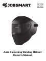
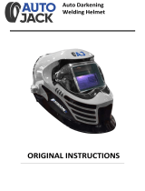
JobSmart 1875790 Welding Helmet Owner's manual
- Category
- Welding System
- Type
- Owner's manual

Auto Darkening Welding Helmet
Owner’s Manual
1875790
1875791
1875792

1
Read & Understand All Instructions Before Using
WARNING
SAFETY WARNINGS - READ BEFORE USING
Professional Quality
Welding Helmet
WARNING
WARNING
Severe personal injury could occur if the user fails to follow the above
mentioned warnings, and/or fails to follow the operating instructions.
Auto-Darkening welding helmets are designed to protect the eyes and face from sparks,
spatter and harmful radiation under normal welding conditions. Auto-Darkening filter
automatically changes from a light state to a dark state when an arc is struck and it
returns to the light state when welding stops.
The Auto-Darkening welding helmet comes assembled. But before it can be used, it must
be adjusted to fit the user properly. Check battery surfaces and contacts and clean it if
necessary. Verify if the battery is in good condition and installed properly. Set up for delay
time, sensitivity and shade number for your application.
The helmet should be stored in dry, cool and dark area and remove the battery, when not
using it for a long time.
•
•
•
•
•
•
•
•
•
•
•
•
•
•
•
This Auto-Darkening welding helmet is not suitable for laser welding and oxyacetylene
welding / cutting processes.
Never place this helmet and Auto-Darkening filter on a hot surface.
Never open or tamper with the Auto-Darkening filter.
This Auto-Darkening welding helmet will not protect against severe impact hazards.
This helmet will not protect against explosive devices or corrosive liquids.
Do not make any modifications to either the filter or helmet, unless specified in this
manual. Do not use replacement parts other than those specified in this manual.
Unauthorized modifications and replacement parts will void the warranty and expose
the operator to the risk of personal injury.
Should this helmet not darken upon striking an arc, stop welding immediately and
contact your supervisor or your dealer.
Do not immerse the filter in water.
Do not use any solvents on the filter screen or helmet components.
Use only at temperatures: -10°C ~ +55°C (14°F ~ 131°F).
Storing temperature: -20°C ~ +70°C (- 4°F ~ 158°F). The helmet should be stored in dry
cool and dark area and remove the battery, when not using it for a long time.
Protect filter from contact with liquid and dirt.
Clean the filter surface regularly; do not use strong cleaning solutions. Always keep the
sensors and solar cells clean using a clean lint-free tissue.
Regularly replace the cracked / scratched / pitted front cover lens.
The materials which may come into contact with the wearer’s skin can cause allergic
reactions in some circumstances.

2
fig.1
• BATTERY INSTALLATION
Install battery into helmet properly, according to
positive and negative terminal marking on battery
jar (See fig.1).
• TEST
Press and hold test to preview shade selection
before welding (See fig.1). When released then
viewing window will automatically return to the
light state (Shade 3).
• POWER
This ADF cartridge is powered by solar cell and 1 AAA Alkaline battery. Replace battery
when LOW BATTERY light is lit (See fig.1).
• SELECTING SHADE LEVEL
Select the shade level you require according to the welding process you will use by
referring to the “Shade Guide Table” below for settings. Turn the shade control knob on the
side of the helmet to the shade number required.
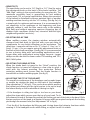
• SENSITIVITY
The sensitivity can be set to “HI” (high) or “LO” (low) by using
the adjustment knob on the back of the shade cartridge. The
“Mid-High” setting is the normal setting for everyday use. The
maximum sensitivity level is appropriate for low welding
current work, TIG, or special applications. Where the operation
of the helmet is disturbed by excess ambient light, or another
welding machine close by, use the “LO” setting. (See fig.2a). As
a simple rule for optimum performance, it is recommended to
set sensitivity to the maximum at the beginning and then
gradually reduce it, until the filter reacts only to the welding
light flash and without annoying spurious triggering due to
ambient light conditions (direct sun, intensive artificial light,
neighbouring welder's arcs etc.).
• SELECTING DELAY TIME
When welding ceases, the viewing window automatically
changes from dark back to light but with a pre-set delay to
compensate for any bright afterglow on the workpiece. The
delay time / response can be set to “S” (short: 0.1 sec.) or “L”
(long: 1.0 sec.). As you require using the adjustment knob on
the back of the shade cartridge. (See fig.2b). It is recommended
to use a shorter delay with spot welding applications and a
longer delay with applications using higher currents. Longer
delays can also be used for lower current TIG welding, and TIG /
MIG / MAG pulse.
• SELECTING THE GRIND OPTION
When the shade knob is turned to the “Grind” position, the
shade function is turned off allowing a clear view to grind a
weld with the helmet providing face protection. Before
restarting welding work, ensure that the shade function is
turned back on before welding again (See fig.3).
• ADJUSTING THE FIT OF THE HELMET
The overall circumference of the headgear can be made larger
or smaller by rotating the knob on the back of the headgear
(See adjustment “Y” in fig.4). This can be done whilst wearing
the helmet and allows just the right tension to be set to keep
the helmet firmly on the head without it being too tight.
• If the headgear is riding too high or too low on your head,
adjust the strap which passes over the top of your head. To do
this release the end of the band by pushing the locking pin out of the hole in the band. Slide
the two portions of the band to a greater or lesser width as required and push the locking
pin through the nearest hole (See adjustment “W” in fig.4).
• Test the fit of the headgear by lifting up and closing down the helmet a few times while
wearing it. If the headgear moves while tilting, re-adjust it until it is stable.
• ADJUSTING THE DISTANCE BETWEEN THE HELMET AND THE FACE
Step 1: Undo the block nut (See “T” in fig.4) to adjust the distance between the helmet and
your face in the down position.
Step 2: Loosen the block nut on either side of the helmet and slide it nearer or further from
your face (See adjustment “Z” in fig.4). It is important that your eyes are each the same
distance from the lens. Otherwise the darkening effect may appear uneven.
Step 3: Re-tighten the block nut when adjustment is complete.
• ADJUSTING VIEW ANGLE POSITION
TILT: Tilt adjustment is located on right side of helmet. Loosen the right headgear tension
knob and push the top end of the adjustment lever outward until the lever’s Stop Tab clears
the notches. Then rotate the lever forward or back to the desired tilt position. The Stop will
automatically engage again when released locking the helmet into position (See fig.5).
• You are now ready to use the helmet. The shading may be adjusted during use by
re-setting the potentiometer control.
LOW BATTERY
WARNING
The user must stop using the auto-darkening welding helmet immediately if
the above-mentioned problems cannot be corrected. Contact the dealer.
INSTRUCTIONS FOR USE
WARNING! Before using the helmet for welding, ensure that you have read and understood the safety instructions.
COMMON PROBLEMS AND REMEDIES
• Irregular Darkening Dimming
Headgear has been set unevenly and there is an uneven distance from the eyes to the
filter lens (Reset the headgear to reduce the difference to the filter).
• Auto-Darkening filter does not darken or flickers
Front cover lens is soiled or damaged (Change the cover lens).
Sensors are soiled (Clean the sensors surface).
Welding current is too low (Adjust the sensitivity level to higher).
Check battery and verify that it's in good condition and installed properly. Also, check
battery surfaces and contacts and clean if necessary. Please refer to the “POWER” on
page 2.
• Slow response
Operating temperature is too low (Do not use at temperatures below -10°C or 14°F).
• Poor vision
Front / inside cover lens and / or the filter is soiled (Change lens).
There is insufficient ambient light.
Shade number is incorrectly set (Reset the shade number).
Check if removing the film on the front cover lens.
• Welding helmet slips
Headgear is not properly adjusted (Readjust the headgear).

3
Tilt
Adjustment
Fore-Aft
Adjustment fig.5
fig.2a
fig.2b
fig.3
fig.4
• BATTERY INSTALLATION
Install battery into helmet properly, according to
positive and negative terminal marking on battery
jar (See fig.1).
• TEST
Press and hold test to preview shade selection
before welding (See fig.1). When released then
viewing window will automatically return to the
light state (Shade 3).
• POWER
This ADF cartridge is powered by solar cell and 1 AAA Alkaline battery. Replace battery
when LOW BATTERY light is lit (See fig.1).
• SELECTING SHADE LEVEL
Select the shade level you require according to the welding process you will use by
referring to the “Shade Guide Table” below for settings. Turn the shade control knob on the
side of the helmet to the shade number required.
• SENSITIVITY
The sensitivity can be set to “HI” (high) or “LO” (low) by using
the adjustment knob on the back of the shade cartridge. The
“Mid-High” setting is the normal setting for everyday use. The
maximum sensitivity level is appropriate for low welding
current work, TIG, or special applications. Where the operation
of the helmet is disturbed by excess ambient light, or another
welding machine close by, use the “LO” setting. (See fig.2a). As
a simple rule for optimum performance, it is recommended to
set sensitivity to the maximum at the beginning and then
gradually reduce it, until the filter reacts only to the welding
light flash and without annoying spurious triggering due to
ambient light conditions (direct sun, intensive artificial light,
neighbouring welder's arcs etc.).
• SELECTING DELAY TIME
When welding ceases, the viewing window automatically
changes from dark back to light but with a pre-set delay to
compensate for any bright afterglow on the workpiece. The
delay time / response can be set to “S” (short: 0.1 sec.) or “L”
(long: 1.0 sec.). As you require using the adjustment knob on
the back of the shade cartridge. (See fig.2b). It is recommended
to use a shorter delay with spot welding applications and a
longer delay with applications using higher currents. Longer
delays can also be used for lower current TIG welding, and TIG /
MIG / MAG pulse.
• SELECTING THE GRIND OPTION
When the shade knob is turned to the “Grind” position, the
shade function is turned off allowing a clear view to grind a
weld with the helmet providing face protection. Before
restarting welding work, ensure that the shade function is
turned back on before welding again (See fig.3).
• ADJUSTING THE FIT OF THE HELMET
The overall circumference of the headgear can be made larger
or smaller by rotating the knob on the back of the headgear
(See adjustment “Y” in fig.4). This can be done whilst wearing
the helmet and allows just the right tension to be set to keep
the helmet firmly on the head without it being too tight.
• If the headgear is riding too high or too low on your head,
adjust the strap which passes over the top of your head. To do
this release the end of the band by pushing the locking pin out of the hole in the band. Slide
the two portions of the band to a greater or lesser width as required and push the locking
pin through the nearest hole (See adjustment “W” in fig.4).
• Test the fit of the headgear by lifting up and closing down the helmet a few times while
wearing it. If the headgear moves while tilting, re-adjust it until it is stable.
• ADJUSTING THE DISTANCE BETWEEN THE HELMET AND THE FACE
Step 1: Undo the block nut (See “T” in fig.4) to adjust the distance between the helmet and
your face in the down position.
Step 2: Loosen the block nut on either side of the helmet and slide it nearer or further from
your face (See adjustment “Z” in fig.4). It is important that your eyes are each the same
distance from the lens. Otherwise the darkening effect may appear uneven.
Step 3: Re-tighten the block nut when adjustment is complete.
• ADJUSTING VIEW ANGLE POSITION
TILT: Tilt adjustment is located on right side of helmet. Loosen the right headgear tension
knob and push the top end of the adjustment lever outward until the lever’s Stop Tab clears
the notches. Then rotate the lever forward or back to the desired tilt position. The Stop will
automatically engage again when released locking the helmet into position (See fig.5).
• You are now ready to use the helmet. The shading may be adjusted during use by
re-setting the potentiometer control.
9
10
11
12
13
GRIND
‘W’
‘Y’
‘Z’‘Z’ ‘T’
‘T’
TOP

4
• BATTERY INSTALLATION
Install battery into helmet properly, according to
positive and negative terminal marking on battery
jar (See fig.1).
• TEST
Press and hold test to preview shade selection
before welding (See fig.1). When released then
viewing window will automatically return to the
light state (Shade 3).
• POWER
This ADF cartridge is powered by solar cell and 1 AAA Alkaline battery. Replace battery
when LOW BATTERY light is lit (See fig.1).
• SELECTING SHADE LEVEL
Select the shade level you require according to the welding process you will use by
referring to the “Shade Guide Table” below for settings. Turn the shade control knob on the
side of the helmet to the shade number required.
• SENSITIVITY
The sensitivity can be set to “HI” (high) or “LO” (low) by using
the adjustment knob on the back of the shade cartridge. The
“Mid-High” setting is the normal setting for everyday use. The
maximum sensitivity level is appropriate for low welding
current work, TIG, or special applications. Where the operation
of the helmet is disturbed by excess ambient light, or another
welding machine close by, use the “LO” setting. (See fig.2a). As
a simple rule for optimum performance, it is recommended to
set sensitivity to the maximum at the beginning and then
gradually reduce it, until the filter reacts only to the welding
light flash and without annoying spurious triggering due to
ambient light conditions (direct sun, intensive artificial light,
neighbouring welder's arcs etc.).
• SELECTING DELAY TIME
When welding ceases, the viewing window automatically
changes from dark back to light but with a pre-set delay to
compensate for any bright afterglow on the workpiece. The
delay time / response can be set to “S” (short: 0.1 sec.) or “L”
(long: 1.0 sec.). As you require using the adjustment knob on
the back of the shade cartridge. (See fig.2b). It is recommended
to use a shorter delay with spot welding applications and a
longer delay with applications using higher currents. Longer
delays can also be used for lower current TIG welding, and TIG /
MIG / MAG pulse.
• SELECTING THE GRIND OPTION
When the shade knob is turned to the “Grind” position, the
shade function is turned off allowing a clear view to grind a
weld with the helmet providing face protection. Before
restarting welding work, ensure that the shade function is
turned back on before welding again (See fig.3).
• ADJUSTING THE FIT OF THE HELMET
The overall circumference of the headgear can be made larger
or smaller by rotating the knob on the back of the headgear
(See adjustment “Y” in fig.4). This can be done whilst wearing
the helmet and allows just the right tension to be set to keep
the helmet firmly on the head without it being too tight.
• If the headgear is riding too high or too low on your head,
adjust the strap which passes over the top of your head. To do
this release the end of the band by pushing the locking pin out of the hole in the band. Slide
the two portions of the band to a greater or lesser width as required and push the locking
pin through the nearest hole (See adjustment “W” in fig.4).
• Test the fit of the headgear by lifting up and closing down the helmet a few times while
wearing it. If the headgear moves while tilting, re-adjust it until it is stable.
• ADJUSTING THE DISTANCE BETWEEN THE HELMET AND THE FACE
Step 1: Undo the block nut (See “T” in fig.4) to adjust the distance between the helmet and
your face in the down position.
Step 2: Loosen the block nut on either side of the helmet and slide it nearer or further from
your face (See adjustment “Z” in fig.4). It is important that your eyes are each the same
distance from the lens. Otherwise the darkening effect may appear uneven.
Step 3: Re-tighten the block nut when adjustment is complete.
• ADJUSTING VIEW ANGLE POSITION
TILT: Tilt adjustment is located on right side of helmet. Loosen the right headgear tension
knob and push the top end of the adjustment lever outward until the lever’s Stop Tab clears
the notches. Then rotate the lever forward or back to the desired tilt position. The Stop will
automatically engage again when released locking the helmet into position (See fig.5).
• You are now ready to use the helmet. The shading may be adjusted during use by
re-setting the potentiometer control.
NOTE:
SMAW – Shielded Metal Arc Welding
MIG (Heavy) – MIG on Heavy Metals
PAW – Plasma Arc Welding
SAW – Shielded Semi-Automatic Arc Welding
TIG, GTAW – Gas Tungsten Arc Welding
MIG (Light) – MIG on Light Alloys
PAC – Plasma Arc Cutting
MAG/CO2 - Metal Active Gas
10 11
SMAW
MIG(heavy)
MIG(light)
TIG,GTAW
MAG/CO2
SAW
PAC
PAW
910 11 12 13 14
12 13 14
12 13 14 15
10 11
12 13 14
10
911
12 13 15
14
10 11
12 13
11
12 13 15
14
1110
98
12 13 15
14
11
10
Welding Process 0.5 2010 40 80 125 175 275 450350
500
400
300
250
200150
100
60
3015
5
1
225
2.5
ARC CURRENT Amperes
SHADE GUIDE TABLE (NO.1)

5
fig.6 fig.7
MAINTENANCE
• REPLACING FRONT COVER LENS
To replace the front cover lens remove lens cassette by unlocking the holder lock below
the cartridge (fig.6), lift up the cartridge to remove / replace the front cover lens.
• REPLACING INSIDE COVER LENS
Replace the inside cover lens if it is damaged. Place your fingernail in recess below
cartridge view window and flex lens upwards until it releases from edges of cartridge
view window.
• CHANGE THE AUTO DARKENING FILTER
Remove ADF holder assembly from helmet shell. See fig.6 for removal. Flex top end of
the ADF holder to allow for ADF cartridge to be removed from frame. Install new ADF
cartridge into frame per fig.7 below. Make sure that the ADF cartridge is inserted in ADF
holder correctly as shown. Install ADF holder assembly into helmet shell.
• CLEANING
Clean helmet by wiping with a soft cloth. Clean the auto darkening filter surfaces
regularly. Do not use strong cleaning solutions. Clean sensors and solar cells with
methylated spirit and a clean cloth and wipe dry with a lint-free cloth.
• BATTERY INSTALLATION
Install battery into helmet properly, according to
positive and negative terminal marking on battery
jar (See fig.1).
• TEST
Press and hold test to preview shade selection
before welding (See fig.1). When released then
viewing window will automatically return to the
light state (Shade 3).
• POWER
This ADF cartridge is powered by solar cell and 1 AAA Alkaline battery. Replace battery
when LOW BATTERY light is lit (See fig.1).
• SELECTING SHADE LEVEL
Select the shade level you require according to the welding process you will use by
referring to the “Shade Guide Table” below for settings. Turn the shade control knob on the
side of the helmet to the shade number required.
• SENSITIVITY
The sensitivity can be set to “HI” (high) or “LO” (low) by using
the adjustment knob on the back of the shade cartridge. The
“Mid-High” setting is the normal setting for everyday use. The
maximum sensitivity level is appropriate for low welding
current work, TIG, or special applications. Where the operation
of the helmet is disturbed by excess ambient light, or another
welding machine close by, use the “LO” setting. (See fig.2a). As
a simple rule for optimum performance, it is recommended to
set sensitivity to the maximum at the beginning and then
gradually reduce it, until the filter reacts only to the welding
light flash and without annoying spurious triggering due to
ambient light conditions (direct sun, intensive artificial light,
neighbouring welder's arcs etc.).
• SELECTING DELAY TIME
When welding ceases, the viewing window automatically
changes from dark back to light but with a pre-set delay to
compensate for any bright afterglow on the workpiece. The
delay time / response can be set to “S” (short: 0.1 sec.) or “L”
(long: 1.0 sec.). As you require using the adjustment knob on
the back of the shade cartridge. (See fig.2b). It is recommended
to use a shorter delay with spot welding applications and a
longer delay with applications using higher currents. Longer
delays can also be used for lower current TIG welding, and TIG /
MIG / MAG pulse.
• SELECTING THE GRIND OPTION
When the shade knob is turned to the “Grind” position, the
shade function is turned off allowing a clear view to grind a
weld with the helmet providing face protection. Before
restarting welding work, ensure that the shade function is
turned back on before welding again (See fig.3).
• ADJUSTING THE FIT OF THE HELMET
The overall circumference of the headgear can be made larger
or smaller by rotating the knob on the back of the headgear
(See adjustment “Y” in fig.4). This can be done whilst wearing
the helmet and allows just the right tension to be set to keep
the helmet firmly on the head without it being too tight.
• If the headgear is riding too high or too low on your head,
adjust the strap which passes over the top of your head. To do
this release the end of the band by pushing the locking pin out of the hole in the band. Slide
the two portions of the band to a greater or lesser width as required and push the locking
pin through the nearest hole (See adjustment “W” in fig.4).
• Test the fit of the headgear by lifting up and closing down the helmet a few times while
wearing it. If the headgear moves while tilting, re-adjust it until it is stable.
• ADJUSTING THE DISTANCE BETWEEN THE HELMET AND THE FACE
Step 1: Undo the block nut (See “T” in fig.4) to adjust the distance between the helmet and
your face in the down position.
Step 2: Loosen the block nut on either side of the helmet and slide it nearer or further from
your face (See adjustment “Z” in fig.4). It is important that your eyes are each the same
distance from the lens. Otherwise the darkening effect may appear uneven.
Step 3: Re-tighten the block nut when adjustment is complete.
• ADJUSTING VIEW ANGLE POSITION
TILT: Tilt adjustment is located on right side of helmet. Loosen the right headgear tension
knob and push the top end of the adjustment lever outward until the lever’s Stop Tab clears
the notches. Then rotate the lever forward or back to the desired tilt position. The Stop will
automatically engage again when released locking the helmet into position (See fig.5).
• You are now ready to use the helmet. The shading may be adjusted during use by
re-setting the potentiometer control.

6
TECHNICAL SPECIFICATIONS
96 x 40 mm (3.78" x 1.57")
110 x 90 x 9 mm (4.33" x 3.54" x 0.35")
2
Shade 3
Variable Shade 9 ~ 13
External, Variable Shade
Automatic On / Off
Low — High, by infinite adjustment knob
Up to Shade DIN16 at all times
Solar cell. Battery replaceable,
1 x AAA Alkaline battery
1/25,000 s. from Light to Dark
0.1 ~ 1.0 s by infinite adjustment knob
≥ 10 amps (DC); ≥ 10 amps (AC)
Yes
Yes
Yes, red light
-10 °C ~ +55 °C (14 °F ~ 131 °F)
-20 °C ~ +70 °C (- 4 °F ~ 158 °F)
High Impact Resistance Nylon
480 g
Stick Welding (SMAW); TIG DC∾ TIG Pulse DC;
TIG Pulse AC; MIG/MAG/CO2; MIG/MAG Pulse;
Plasma Arc Cutting (PAC); Plasma Arc Welding (PAW);
Air Carbon Arc Cutting (CAC-A); Grinding
ANSI Z87.1, CAN/CSA Z94.3
Viewing Area:
Cartridge Size:
Arc Sensor:
Light State:
Dark State:
Shade Control:
Power On/Off:
Sensitivity Control:
UV/IR Protection:
Power Supply:
Switching Time:
Delay (Dark to Light):
Low Amperage TIG Rated:
Grinding:
Battery Capacity Test:
Low Battery Indicator:
Operating Temp.:
Storing Temp.:
Helmet Material:
Total Weight:
Application Range:
Approved:

PARTS LIST & ASSEMBLY
1
2
3
4
5
6
7
8
9
10
11
12
2
1
1
2
2
2
1
1
1
1
1
1
Part List of H*
ITEM DESCRIPTION QTY
Sweatband
Washer
Washer
Fixed Washer
Rubber Washer
Block Nut
Gear Washer
Angle Limitation Washer
Right Boot Screw
Left Boot Screw
Adjustable Headband
Front Headgear
Shell (Welding Mask)
Rubber Holder
Front Cover Lens
Auto-Darkening Filter
Inside Cover Lens
Holder Lock
Lens Holder
Headgear Assembly (Including Sweatband)
A
B
C
D
E
F
G
H*
1
1
1
1
1
1
1
1
Part List
ITEM DESCRIPTION QTY
BC E
DFG
A
H
1
1
23456
65478910
11
12
-
 1
1
-
 2
2
-
 3
3
-
 4
4
-
 5
5
-
 6
6
-
 7
7
-
 8
8


JobSmart 1875790 Welding Helmet Owner's manual
- Category
- Welding System
- Type
- Owner's manual
Ask a question and I''ll find the answer in the document
Finding information in a document is now easier with AI
Other documents
-
SCANGRIP MAG PRO Multipurpose and Rechargeable LED Work Light User guide
-
ESAB A50 User manual
-
 Autojack WH100W Owner's manual
-
ESAB Auto-Darkening Welding Helmets User manual
-
METAL MAN ATEC8735SGC User manual
-
 Shop Iron 8820078 Owner's manual
-
URREA USCS4 Owner's manual
-
Westfalia 76 53 13 User manual
-
Surtek 137336 Owner's manual
-
Hobart Endeavor Series Owner's manual

