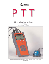
Stahlwille Sensotork 712 Operating Instructions Manual

Category
Measuring, testing & control
Type
Operating Instructions Manual
EN
Operating Instructions
STAHLWILLE
Sensotork 712 electronic torque wrench
Sensotork 713 electronic torque/angle-controlled wrench
Version 10/2017 91 97 98 14
EN
Foreword
These operating instructions are to assist with the
correct,
safe and
economic
usage of the electronic torque wrench.
Target group for these Operating
Instructions
These operating instructions are for the information of
users of the electronic torque/angle-controlled
wrenches.
We assume that the user possesses basic technical
knowledge.
Any person who
sets up,
programmes,
operates,
services, or
disposes
the torque/angle-controlled wrench must have read
the contents of these operating instructions and fully
understood them.
If any of the details in these operating instructions is
not clear, or information is found to be lacking, then
please get in contact with EDUARD WILLE
GmbH & Co. KG. The full address can be found on the
last page of the operating instructions.
EN
Display panel and buttons
Functions of the arrow buttons to the right of the
display panel
Wrench switched off
Wrench switched on –
outside wrench menu
Within a wrench menu
When inputting a value or text
Optical warning signals
Menu structure
Adjusting parameters +
New adjusting parameters
–Mode (only Sensotork 713)
–Torque ×
–Snug point #
–Rotational angle #
–Tolerance [+/- absolute value]
–Pre-warning [%]
–Adaptor length
–Measurement unit
–Name parameter
Adjusting parameters 1
–[...]
–Delete parameters
Adjusting parameters ...
–[...]
Define process+
Define new process
–Adjusting parameters 1
–Adjusting parameters ...
–Name
Process 1
–Adjusting parameters 1
–Adjusting parameters ...
–Delete process
Process ...
–[...]
Presets +
Change administrator's password
Measurement unit
Adaptor length
Switch-off time
Object number
Erase memory
Stored values
Adjusting parameters 1
–Data 1
–Data...
–Delete data
Adjusting parameters ...
Status
Serial number
Object number
Software version
Measuring range
+Only accessible for the administrator
#Sensotork 713 only in torque angle mode
×Sensotork 712, Sensotork 713 only in torque
mode
O/U scan through selected positions on the
display panel, e.g. 1, 2, 3 or A, B, C
L/R select a position on the display with the
cursor
Any
b u t t on Activate
MR ascertain tare
ML change to wrench menu
O/U quick selection (scan through wrench
operations)
L/R select unit of measure
L and R Direct mode (snug point/ rotational angle)
Sensotork 713 only.
ML Break/Back
MR Select/Confirm
O/U Scan menu
ML Break/Back
MR Confirm/OK
L/R Move cursor to right or left
O/U Scan through letters or figures
red LED outside the range of tolerance
green LED within the range of tolerance
EN
Table of contents
Display panel and buttons . . . . . . . . . . . . . . . . . . 3
Menu structure . . . . . . . . . . . . . . . . . . . . . . . . . . . 3
Introduction to the operating instructions . . . . . 5
Explanation of the information on dangers . . . . . . . 5
Availability. . . . . . . . . . . . . . . . . . . . . . . . . . . . . . . . 5
Supplements. . . . . . . . . . . . . . . . . . . . . . . . . . . . . . .5
Printing conventions . . . . . . . . . . . . . . . . . . . . . . . . .5
Important safety instructions. . . . . . . . . . . . . . . . 5
Proper use. . . . . . . . . . . . . . . . . . . . . . . . . . . . . . . . 5
Duties on use of these operating instructions. . . . . .5
Basic safety instructions . . . . . . . . . . . . . . . . . . . . . .6
Handling rechargeable batteries and batteries . . . . .6
Technical description . . . . . . . . . . . . . . . . . . . . . . 6
Both types. . . . . . . . . . . . . . . . . . . . . . . . . . . . . . . . 6
In addition, the
Sensotork 713 model ... . . . . . . . . . . . . . . . . . . . . . .7
Identification . . . . . . . . . . . . . . . . . . . . . . . . . . . . . . .7
Accuracy . . . . . . . . . . . . . . . . . . . . . . . . . . . . . . . . . .7
Internal torque wrench software . . . . . . . . . . . . . . . .7
Transportation, package contents and storage. 7
Basic principles of operation. . . . . . . . . . . . . . . . 7
Preparing the torque wrench. . . . . . . . . . . . . . . . . . 7
Buttons . . . . . . . . . . . . . . . . . . . . . . . . . . . . . . . . . . .9
Display panel. . . . . . . . . . . . . . . . . . . . . . . . . . . . . . .9
Switching on the torque wrench . . . . . . . . . . . . . . .10
Password protection . . . . . . . . . . . . . . . . . . . . . . . .10
Overview of the menus . . . . . . . . . . . . . . . . . . . . . .10
Moving around the menus. . . . . . . . . . . . . . . . . . . .10
Input of numbers and texts . . . . . . . . . . . . . . . . . . .10
Functioning . . . . . . . . . . . . . . . . . . . . . . . . . . . . . 10
Sensotork Operating Modes . . . . . . . . . . . . . . . . . 10
Examples for adjusting parameters and
define process settings . . . . . . . . . . . . . . . . . . . 11
An example of an adjusting parameter,
tightening function and define process . . . . . . . . . 11
Input of data for a tightening define process. . . . . .12
Operating the torque wrench. . . . . . . . . . . . . . . 13
Ascertaining the tare of the wrench. . . . . . . . . . . . .13
Calling up adjusting operations and define
process . . . . . . . . . . . . . . . . . . . . . . . . . . . . . . . . . .14
Tightening . . . . . . . . . . . . . . . . . . . . . . . . . . . . . . . .14
Resetting the torque wrench. . . . . . . . . . . . . . . . . .18
Further settings. . . . . . . . . . . . . . . . . . . . . . . . . . 18
Presets . . . . . . . . . . . . . . . . . . . . . . . . . . . . . . . . . 18
Memory is full . . . . . . . . . . . . . . . . . . . . . . . . . . . . .19
Switching-off the torque wrench . . . . . . . . . . . . . . .20
Viewing and deleting stored values. . . . . . . . . . . . .20
Displaying the status. . . . . . . . . . . . . . . . . . . . . . . .20
Connecting the torque wrench to a PC . . . . . . 20
Troubleshooting . . . . . . . . . . . . . . . . . . . . . . . . . 21
Cleaning. . . . . . . . . . . . . . . . . . . . . . . . . . . . . . . . 21
Repairs, maintenance and adjustment. . . . . . . 21
Technical data. . . . . . . . . . . . . . . . . . . . . . . . . . . 22
Accuracy. . . . . . . . . . . . . . . . . . . . . . . . . . . . . . . . . 22
Accessories. . . . . . . . . . . . . . . . . . . . . . . . . . . . . 22
Insert tools . . . . . . . . . . . . . . . . . . . . . . . . . . . . . . 22
For the PC connection . . . . . . . . . . . . . . . . . . . . . . 22
For testing and re-adjusting . . . . . . . . . . . . . . . . . . 22
Service . . . . . . . . . . . . . . . . . . . . . . . . . . . . . . . . . . 22
Disposal. . . . . . . . . . . . . . . . . . . . . . . . . . . . . . . . 22
EN
5
Introduction to the
operating instructions
Explanation of the information on
dangers
The following categories of notices are contained in
these operating instructions:
Availability
If these operating instructions are lost or become
unusable, a new copy can be ordered from EDUARD
WILLE GmbH & Co. KG.
If the equipment has not been registered, the following
details will be required for ordering a new copy:
Serial number of the torque/angle-controlled
wrench
Name of dealer
Date of purchase.
The order number of the operating instructions can be
found on the bottom right of the title page.
Supplements
Update the operating instructions regularly in line with
legal requirements regarding accident prevention,
environmental protection and
trade association rules governing the place of work.
Printing conventions
Various elements of the operating instructions are
printed in line with laid-down conventions. In this way,
it is easy to differentiate between
normal text,
lists,
or directions.
Comments with this sign contain details pertaining
to the economic use of the torque wrench.
In this introduction, for the sake of clarity, the
expression "Torque Wrench" is used.
Differences which exist between the Sensotork 712
and Sensotork 713 torque wrenches will be explained.
Important safety
instructions
Proper use
The Sensotork 712 electronic torque wrench and the
Sensotork 713 electronic torque/angle-controlled
wrench have been developed to measure torques
during the controlled tightening and loosening of
threaded connections in the workshop sector. To do
this, an appropriate plug-in tool must be connected to
the torque wrench.
The Sensotork 713 electronic torque wrench/angle-
controlled wrench can additionally be used for
measuring rotational angles without a reference arm.
Proper use includes complete observance of the
information contained in these operating instructions.
Observe the safety instructions and the technical limit
values.
The relevant accident prevention regulations of the
responsible trade association and all other applicable
safety regulations must also be observed.
The Sensotork 712 electronic torque wrench and the
Sensotork 713 electronic torque/angle-controlled
wrench may only be used for the specified purposes
(see page 10).
STAHLWILLE accepts no liability for damage arising
due to improper use.
Duties on use of these operating
instructions
The user of the torque wrench is responsible for the
constant availability of these operating instructions
when working with the torque wrench. Store the
operating instructions in the vicinity of the torque
wrench.
DANGER
Notices containing the word DANGER
warn of hazards which lead to severe or
fatal injuries.
WARNING
Notices containing the word WARNING
warn of hazards which lead to severe
injuries.
CAUTION
Notices containing the word CAUTION
warn of hazards which lead to injuries.
ATTENTION
These notices warn of a situation which leads
to material or environmental damage.
EN
6
Basic safety instructions
The torque wrenches are precision tools and must
accordingly be treated with care. Avoid mechanical,
chemical or thermal influences which exceed the
stresses involved in proper use.
Make sure that extreme climatic conditions such as
cold, heat and humidity are unable to influence
accuracy.
Avoiding risks of injury
Never use a damaged torque wrench or damaged
accessories.
Rechargeable batteries and batteries must be
kept out of the reach of children. Children may put
these into their mouths and swallow them.
Do not use the torque wrench as an impact tool.
All plug-in tools and connectors which are used
must be firmly connected and correctly inserted.
Do not overload the torque wrench. Never exceed
a limit torque of 130% of the nominal value.
Observe the specifications on the type plate under
all circumstances.
Example of a type plate:
Avoiding damage to the torque wrench
Do not allow any foreign bodies or fluids to enter
the torque wrench housing. Always cover unused
sockets.
Never open the torque wrench housing.
Do not press on the display.
Leaking batteries and rechargeable batteries may
cause damage to the torque wrench. If the torque
wrench is not used for a long time, remove the
batteries.
Do not use the torque wrench for the uncontrolled
loosening of seized threaded connections.
Do not kink the cables and connectors, and never
expose these to excessive tensile forces or
temperatures.
Do not overload the torque wrench. Never exceed
a limit torque of 130% of the nominal value.
Avoiding malfunctions
Make sure that connectors are completely
inserted into the connection sockets.
Handling rechargeable batteries and
batteries
Rechargeable batteries and batteries may contain
poisonous substances which pollute the
environment.
They must be kept out of the reach of children.
Children may put the rechargeable batteries and
batteries in their mouths and swallow them.
Therefore, always dispose of rechargeable
batteries and batteries according to the applicable
legal regulations. Never throw rechargeable
batteries and batteries in the normal domestic
waste.
Leaking batteries and rechargeable batteries may
cause damage to the torque wrench. If the torque
wrench is not used for a long time, remove the
batteries. If a battery has leaked, put on protective
gloves and clean the battery compartment with a
dry cloth.
Replace weakening rechargeable batteries and
batteries in good time. Always replace all
rechargeable batteries and batteries at the same
time, and use rechargeable batteries and
batteries of the same type (see page 9).
Technical description
Both types
1. Inserting tools
2. Display panel and buttons
3. Rotation lock
4. Socket for PC connection
5. Insert ratchet 735
The torque wrenches are adjustable, indicating torque
wrenches with a display panel.
1
3
4
5
2
EN
7
Properties of the torque wrenches:
Clockwise or anti-clockwise torque can be set.
Readings are made independent of point of
application of force (not in versions 712/713 size
40)
Various units of measure ( N·m, ft·lb, in·lb) can be
selected.
Adaptor length values for special insert tools can
be simply inputted.
Combined optical, tactile and acoustic (buzzer)
warning signal can be selected.
The torque wrenches have an interface to a PC
USB socket for reading and analysing the stored
data in the PC.
The torque wrenches have a QuickRelease safety
lock for easy release and disconnecting of insert
tools.
The torque wrenches are available in various sizes.
(see page 22).
In addition, the
Sensotork 713 model ...
... can, in addition, measure the rotational angle
without a reference arm.
The torque and the angle are shown simultaneously
on the display panel.
Identification
The torque wrenches can be identified by a serial
number, which is stamped on the side of the wrench
tube and is also shown on the display panel after
switching on. The serial number can also be shown by
selecting the "status" menu item on the display panel.
(see page 20).
Accuracy
The range of measurement is from 5% to 100% of the
rated value.
The torque wrenches meet the requirements of DIN
EN ISO 6789 and DKD-R 3-7, class 2.
Internal torque wrench software
The torque wrench is equipped with a micro-controller
and a storage facility. The evaluation and long-term
storage of the readings is taken over by the internal
software.
Data can be inputted by means of the keyboard or the
interface with the PC.
The output of information is effected by means of the
display panel, light diodes, vibration and sound
signals.
Transportation, package
contents and storage
Only transport the torque wrenches in their case and
see that the cases do not fall during transport.
The package on delivery consists of:
an electronic torque wrench
an insert ratchet 735
a plastic case for size 6 and size 20 or
a steel case for size 40
two AA/LR6, 1,5 V alkaline batteries (mignon)
(see page 9)
a works certificate
an operating instruction
Store the torque wrench in its case at a temperature
between -20 °C to +80 °C.
Basic principles of
operation
Preparing the torque wrench
General requirements
The operator must stand on a firm base while
working.
The operator must have sufficient room for
movement.
The workplace must be adequately illuminated..
The temperature of operation must be between -
10 °C to +60 °C.
Before use the torque wrench must be able to be
adapted to the climatic conditions during later
operation.
The torque wrench must be protected against
potentially damaging influences, for example dirt
or moisture.
ATTENTION
Damage to the torque wrench measurement
elements.
Avoid shock-like mechanical influences such as
e.g. hard jolts or dropping.
EN
8
Selection of interchangeable parts and insert
tools
The tool must also have the correct shape and size for
the engaged object.
Installation of insert tools
Insert the tool in the front side internal square hole
of the wrench head.
By doing this the sprung locking pin of the
QuickRelease safety lock of the insert tool is pressed
down by the insert chamfer.
Push the insert tool further until it engages. The
locking pin must spring into the bore notch of the
QuickRelease safety lock.
Check that the insert tool is firmly in place.
If using an insert ratchet, switch this by turning the
dial to the desired direction of working.
Push the correct interchangeable part on to the
drive square iron of the pawl-action ratchet until it
engages with an audible click.
WARNING
Measuring errors due to incorrectly set
extension and therefore danger of
severe injuries.
Set the appropriate extension for plug-in
tools.
See chapter "Setting the extension",
page 19.
WARNING
Severe injuries due to incorrect inserts
Use only inserts whose form and design
are suitable for the intended use.
WARNING
Severe injuries due to exceeding the
maximum load-bearing capability of the
insert or plug-in tool which is used.
This may be lower than the maximum
permissible torque of the torque
wrench.
Always observe the permissible
maximum load-bearing capability of the
insert or plug-in tool which is used.
CAUTION
Injuries due to unsecured plug-in tools.
Make sure that plug-in tools are secured
against pulling out by engaging the
retaining pin.
EN
9
De-installation of insert tools
Insert tool "normally" inserted
Press the green QuickRelease button on the
underside of the wrench head. (A).
Pull the insert tool out.(B).
Insert tool inserted and turned through 180°
Insert a thin spike from outside into the bore notch
on the upper side of the wrench head.
Press the locking pin down with the spike.(A).
Pull the insert tool out.(B).
Inserting charged batteries
To open the cover of the battery compartment, a
suitable coin, for example will be needed.
Turn the lock in an anti-clockwise direction to the
"UNLOCK" position (1.).
Remove the cover upwards (2.).
The following battery types can also be used:
AA/LR6, 1,5 V alkaline batteries (mignon)
AA/LR6, RAM, 1.2 V, rechargeable batteries
(mignon).
Insert the batteries as indicated in the battery
compartment. Ensure the polarity is correct.
Close the cover of the battery compartment. See
that it sits properly. The lock can only be operated
in the correct position. Turn the lock in a clockwise
direction into the "LOCK" position.
Buttons
Using the six buttons settings can be put in and
functions carried out.
Using the four buttons on the right next to the display
panel the cursor can be moved and/or the menu
selections changed.
Using the "R" or "L" buttons the cursor can be moved
to the right or to the left.
Using the "R" or "L" buttons in the "Display" mode
the unit of measure can be determined. In the
Sensotork 713 select the "Direct" mode by
pressing both "R" and "L" buttons simultaneously.
Using the "O" or "U" buttons the selected positions on
the display panel, such as menus, adjusting
operations, or characters and figures can be leafed
through.
The "MR" and "ML" buttons under the display panel
have various functions. These are shown in plain text
on the display panel.
Display panel
Readings, mode information and other information
depending on operating status is shown on the display
panel.
ATTENTION
Damage to the torque wrench.
Use a suitable charger for AA/LR6 type 1.2 V
rechargeable batteries.
EN
10
Switching on the torque wrench
To switch on the torque wrench, press any button.
Both LEDs light up for a moment to indicate that the
wrench is on. Additionally, the serial number (also
stamped on one side of the wrench tube) and the
software version appears on the display panel.
Press the "ML" button to display the choice of
menu languages.
Select the desired language using the "O" or "U"
buttons.
Confirm selection with the "MR" button.
The torque wrench is ready for operation and is in the
"Display" mode. The instructions will be shown in the
language selected.
When switching-on again, the wrench will
automatically display instructions in the last-
selected language.
If operating the wrench for the first time, or the
batteries were removed for longer than ten minutes,
then it will take up to a minute before the wrench is
ready to use.
When the wrench is not in use, it will switch off after a
certain time. The "shutdown time" can be set using the
"presets" menu (see page 18).
After switching-off all data is stored.
Password protection
The wrench allows all settings to be protected by an
administrator's password (see chapter "Setting and
changing the administrator's password", page 18).
On delivery no administrator's password is set.
As long as no administrator's password has been set,
the password interrogation can be answered by
pressing the "OK" button.
A maximum of 16 characters are available for the
input.
Overview of the menus
There are five main menus:
"adjusting operations"
"define processes"
"presets"
"stored values" and
"status"
Moving around the menus
To enter the main menu, press the "ML" button.
When calling-up certain menu items a password
interrogation appears.
To select a menu item, press the "O" or "U"
button.
Confirm the selected menu item with the "MR"
button.
Depending on the menu item, either a function will be
activated or a sub-menu will appear.
To exit a selected menu, press the "ML" button.
To select a function or a menu item in the sub-
menus, proceed as with making a selection in the
main menu.
Input of numbers and texts
When inputting data into the menu items numerical
values or text must be entered. The input can contain
figures, letters or symbols. Proceed as follows:
Select the position for input using the "L" or "R"
buttons.
The cursor flashes as an input prompt on the display
panel, indicating a position to the left of the character
to be inputted.
Select the desired character using the "O" or "U"
buttons.
Repeat the previous steps until the desired input
is complete.
To scan through the numbers, letters or symbols,
keep the appropriate button pressed.
When inputting a value the previous content of the
field will be shown.
To change the content, confirm the change at the
end with the button "MR" .
If the "return" button "ML" is pressed, then the
input will be discarded and the previous content is
retained.
Functioning
Sensotork Operating Modes
The Type 712 torque wrench controls the torque
mode. The Type 713 torque wrench controls both the
torque as well as the angle mode.
After switching on, the Sensotork 712 and 713 torque
wrenches are always in one of the following four
operating modes.
Track/dial mode
In this operating mode, on completion of a
tightening operation no values are stored.
In this operating mode the current torque value is
measured and shown on the display panel. The
wrench does not react with optical or acoustic signals
when a bolt is tightened.
ATTENTION
Without an administrator password, the torque
wrench can only be used to a limited degree.
Always store the administrator password in a
secure location.
Forward the torque wrench to STAHLWILLE if
you have forgotten your administrator password.
EN
11
Torque
In this operating mode a bolt is tightened only
according to the torque. The wrench evaluates the
torque readings and reacts with corresponding signals
(LED, buzzer, vibration). For this, the values must
have been pre-set into the wrench.
Peak value hold
During a wrenching operation the highest torque value
is measured and shown on the display as the so-
called "Peak value".
By simple choice of parameters the torque wrench can
be set to retain the measured peak value.
Rotational angle (only Sensotork 713)
In this operating mode a bolt is tightened according to
torque and angle values. The wrench evaluates the
torque and angle readings and reacts with
corresponding signals (LED, buzzer, vibration). For
this, the values must have been pre-set into the
wrench.
Direct mode (only for Sensotork 713)
In this operating mode after completing a
wrenching operation no values are stored.
In this special rotational angle mode the snug point
and angle of rotation can be directly inputted. No
complete operation programming is required.
Additionally required parameters are taken over from
the pre-settings.
Online bolting
In this operating mode, a bolting process can be
visualised on a PC monitor. This operating mode is
only available in combination with the
SENSOMASTER software.
Examples for adjusting
parameters and define
process settings
An example of an adjusting
parameter, tightening function and
define process
An object is to be bolted on using three bolts (A, B, C).
The design engineer directs that bolts B and C must
be tightened at a certain angle.
The direction is to begin with bolt A being tightened,
but this only according to torque value.
Each of these three conditions represents an
individual tightening operation, in which the
parameters of the tightening process must be defined
individually.
These are:
torque and/or snug point and rotational angle,
tolerance
measurement unit and
name
The following settings are the same for the tightening
operations shown:
Adaptor length
Pre-warning
The construction engineer must guarantee that the
tightening functions are carried out in a certain order.
For this he additionally enters a define process in the
wrench. The adjusting operations are simply added to
this define process in the desired order.
When the technician carries out the tightening on the
object, then he does not have to pick out the individual
adjusting operations, but only needs to select a
complete define process.
The wrench informs the technician automatically
which operation is the next to be carried out. Each of
the tightening functions ensuing from this creates a
measurement data record, which is permanently
stored in the wrench's memory.
EN
12
Input of data for a tightening define
process
Shown below are the operating steps necessary for
the practical example.
Switching on
To switch the torque wrench on, press any button.
While the wrench is booting-up, both LEDs illuminate.
The boot function lasts around one second. Then the
serial number and the software version appear on the
display panel.
Activate the operating software with the "MR"
button.
The wrench is now ready for operation and is in the
"Track/dial mode".
Input of adjusting parameters
To call-up the menu, press the "ML" button
Enter the administrator's password.
Confirm with the "MR" button.
If no administrator's password has been set,
confirm without further input by means of the "MR"
button.
You are now in the menu and the first menu item
"adjusting operations" is already selected.
To enter the "adjusting operations" sub-menu,
press the button "MR".
In the "adjusting operations" menu
new operations can be drawn up,
or edited (changed or deleted).
Select the item "new adjusting parameters".
Confirm with the button "MR ".
In order to process the settings for adjusting
parameters, select items from the following list of
parameters:
Mode (only Sensotork 713)
Torque and/or snug point and rotational angle
(only Sensotork 713)
Tolerance
Pre-warning
Adaptor length
Measurement unit
Name
The parameters for the first adjusting parameters can
be entered as follows:
To select "Mode", press the "MR" button.
To set the operating mode, select the item "Angle"
from the list, using the "O" or "U" buttons.
Confirm the selection with the "MR" button.
You are back in the list of parameters on the list item
"Mode".
To select the menu item "Snug Point" press the
"U" button.
To set an input for the snug point press the "MR"
button.
The previous value for the snug point is shown on the
display panel. To enter the value 10, proceed as
follows:
Briefly press the "L" button three times in
succession.
The cursor now blinks between the position for
"hundreds" and "tens".
Press the "O" or "U" button until a 1 appears to the
right of the cursor.
To place the cursor in the position between the
"tens" and the "units", press the "R" button once.
Now press the "O" or "U" button, until a 0 appears
to the right of the cursor.
The display panel now shows the value 10 for the snug
point.
Confirm the input with the "MR" button.
The next item can be selected from the list of
parameters.
To select the item "Angle" press the "U" button.
To make an entry, press the "MR" button.
To enter the value 25 degrees, for example, proceed
as follows:
Briefly press the "L" button three times in
succession.
The cursor now blinks in a position between the
"hundreds" and the "tens".
Press the "O" or "U" button, until a 2 appears to
the right of the cursor.
To move the cursor to the position between the
"tens" and "units", press the "R" button once.
Now press the "O" or "U" button until a 5 appears
to the right of the cursor.
The display panel shows the value 25 degrees for the
angle.
Confirm the input with the "MR" button.
The next item can be selected from the list of
parameters.
Enter in the same manner the imaginary values for:
Tolerance (5.6),
Pre-warning [%] (60),
Adaptor length (remains unchanged for now) and
unit (N·m).
DANGER
Danger of severe or fatal injuries due to
take-over of incorrect measured values.
The data and values in the following
example are not guideline values.
Never use example values for a working
process.
ATTENTION
Settings for the bolting type are not stored.
Always complete the input of a bolting type by
assigning a name.
EN
13
To store all settings for a adjusting parameters,
the operation must receive a name.
Select the menu item "Name".
Confirm with the "MR" button.
The cursor is positioned at the left side of the enter
line.
Select the desired characters with the "O" or "U"
button.
To move the cursor to the next position, press the
"R" button.
Select the next character.
Repeat the previous steps until the text "Bolt B"
has been entered.
Confirm the input with the "MR" button.
The adjusting parameters is now stored. In this way,
the data for the first wrenching operation is complete
The menu "adjusting operations" can now be scanned
using the "O" or "U" buttons. This now contains the
newly-inputted adjusting parameters "Bolt B".
Repeat the previous operating steps and enter a
second adjusting parameters with the values from
"Bolt B" and name the second adjusting parameters
"Bolt C".
Enter a third wrenching operation with the following
values:
Mode: Torque
Torque (30)
Tolerance (5)
Pre-warning [%] (80)
Adaptor length (remains unchanged for now)
unit (N·m)
Name (Bolt A)
Select the item "define new parameters" with the
"O" or "U" button.
Confirm with the "MR" button.
Input of a define process
A define process is a collection of adjusting
operations, which are carried out in a preset order.
After the adjusting operations have been inputted, a
define process can be set up
In the "define process" menu
new define process can be set up,
viewed or deleted
If a certain order of wrenching operations is not
necessary, then no define process needs to be set
up. The stored adjusting operations can be
directly selected as well.
Select the item "define processs" in the main
menu using the "O" or "U" button.
Confirm with the "MR" button.
You are now in the "define process" sub-menu.
On the display panel a list with all stored adjusting
operations is shown.
To input a define process, confirm with the "MR"
button.
On the display panel a list with all stored wrenching
operations is shown.
Select the adjusting parameters "Bolt A" using the
"O" or "U" button.
To add adjusting parameters to an define process,
press the "MR" button once .
Take care not to press the "MR" button twice.
Otherwise the selected adjusting parameters will
be added a second time.
The input is confirmed acoustically (buzzer) and by the
green LED briefly lighting up.
The adjusting parameters selected is now the first
operation in the define process.
Now add the adjusting operations "Bolt C" and
"Bolt B" using the "O", "U" and "MR" buttons.
Name the define process "Example".
When a name has been given to a define process,
no further adjusting operations can be added to
this define process.
To leave the menu, press the "ML" button twice.
Operating the torque
wrench
How to set tightening operations and define
processes can be found in the chapter entitled
"Inputting data for wrenching processes" (see
page 12 ) in the practical examples.
Ascertaining the tare of the wrench
In order to guarantee exact readings, the wrench tare
must be ascertained for each adjusting parameters.
This procedure is different for the 712 and 713
models.
ATTENTION
Settings for the sequence plan are not stored.
Always complete the input of a sequence plan
by assigning a name.
DANGER
Danger of severe or fatal injuries due to
incorrect measured values.
Make sure that the torque value is set
correctly prior to use.
Make sure that the insert and/or plug-in
tool which is used is seated securely
prior to use.
ATTENTION
Damage to the torque wrench
The torque wrench must not be overloaded.
Always observe the maximum torque which can
be set (see type plate).
EN
14
Sensotork 712
The tare of the torque is ascertained by pressing the
"Tare" button "MR".
Always ascertain the tare of the wrench, when, in
untensioned state, a value is shown which is
unacceptable for the accuracy.
After ascertaining the tare a value can remain
disparately at 0.00. This should stay within the
required accuracy of the adjusting parameters. If this
is not the case, then repeat the procedure to ascertain
the tare.
Sensotork 713
Ascertaining the torque tare is carried out in the same
way as the 712 model. When the "MR" button is
pressed, however, the rotational angle tare is
additionally ascertained.
The rotational angle value is automatically ascertained
when changing adjusting parameters as well.
Ascertaining the tare of the rotational angle can take
several seconds. During the process the display panel
shows "Tare".
Lay the switched-on torque wrench on a level
surface and hold it firmly.
Press the "MR" button.
The torque wrench now ascertains its tare.
Calling up adjusting operations and
define process
After all adjusting operations have been inputted, the
wrench is ready for operation.
The pre-defined adjusting operations and/or the define
process can be directly selected by means of the quick
selection facility using the "O" or "U" buttons ex-menu.
To call up the stored adjusting operations and/or
define process, press the "O" or "U" buttons
(quick selection facility).
All stored adjusting operations and/or define process
are shown as a list on the display panel.
Select the desired adjusting parameters and/or
define process.
Confirm the selection with the "MR" button.
The first adjusting parameters of a define process is
shown on the display panel.
To discontinue the selection, press the "ML"
button.
After the selection the desired adjusting parameters
and/or the first adjusting parameters of a define
process is activated.
In the 713 model the angle tare is now ascertained, if
a rotational angle adjusting parameters is activated.
Tightening
When carrying out adjusting parameters, apart from
displaying the torque and/or angle, the wrench will
give out further signals, which show the progress of
the adjusting parameters according to the preset
parameters.
While tightening, observe the torque values and/
or angle value indicated on the display panel.
Depending on the operating mode, the following
processes are possible:
Display
The display panel shows the current torque value.
The wrench reports no other occurrences, such as the
reaching of a threshold or barrier value.
DANGER
Danger of severe or fatal injuries due to
incorrect torque values caused by an
incomplete calibration process.
If a plug-in tool is contained in the
torque wrench, allow the plug-in tool to
project e.g. over the edge of a bench
during calibration.
Keep torque/angle-controlled wrench
713 steady throughout the entire
calibration process.
DANGER
Danger of severe or fatal injuries due to
an incorrect sequence when tightening
bolts.
Make sure that the bolts specified by the
sequence plan are tightened in the
relevant, correct sequence.
If you discover that you have confused
the sequence, abort the bolting process
immediately.
Loosen the bolt and use a new bolt if
necessary.
WARNING
Danger of severe injuries due to
overloading the torque wrench.
Do not load the torque wrench past the
maximum measuring range.
In the event of overload, both LEDs
flash, the handle vibrates and the
acoustic signal is sounded at intervals.
In this case, immediately abort the
bolting process.
EN
15
Torque
In this mode the name of the adjusting parameter is
shown in the top line of the display panel. Below this
the current torque value is displayed.
If the torque wrench is activated and the value
approaches the range for the readings, the text in the
display panel above the two menu buttons changes to
"return" and "OK".
Additionally, the unit of measure held for this
tightening operation and the direction of rotation "-" for
anti-clockwise and "+" for clockwise, are shown on the
display panel.
The value displayed is always the maximum value
hitherto reached. This also remains on the display
panel, even when the torque wrench is meanwhile
slackened, for example when re-tensioning.
As soon as this value has been surpassed by further
loading, then the maximum value displayed increases.
If the pre-warn value is reached, the green and red
LEDs light up. This means that the lower tolerance
range of the torque target value will shortly be
reached.
On reaching the tolerance range around the target
torque, the green LED lights up. Additionally, an
acoustic signal buzzes and the vibration alarm is
activated.
If the torque wrench vibrates, the energy
consumption increases steeply.
Release the torque wrench after ending the
tightening operation.
The tightening operation commenced in this way can
only be ended using the menu buttons.
The value reached can now be stored by pressing the
"MR" button, or discontinued by pressing the "ML"
button.
Saving is only possible if "OK" is shown on the
display above the "MR" button. Otherwise, the
memory is full. To be able to save again, you must
at least partially delete the memory.
In both cases the next adjusting parameters can be
initiated immediately.
EN
16
If "OK" is not shown over the "MR" button on the
display panel, then the torque wrench memory is full
(see Chapter "Memory is full", page 19).
If working through a define process, after finishing
adjusting parameters then the next adjusting
parameters within the define process will be
selected. This applies for all operating modes.
After the last adjusting parameters of the define
process the first adjusting parameters will be
automatically selected.
Peak value hold
In the "torque" mode the wrench automatically
remembers the peak value. This value is shown on the
display.
Create a new wrenching function and give it a name.
Set the tolerance value to zero and the pre-warning to
100%. All the other parameters can be taken over
from the pre-settings.
As long as the torque wrench is being operated, the
torque value shown will rise.
After completing the wrenching function, this torque
value will be retained.
WARNING
Danger of severe injuries due to
excessively tight threaded
connections.
If the red light-emitting diode lights up,
immediately abort the bolting process.
Exchange the bolt for a new bolt.
EN
17
Rotational angle
In this mode the name of the adjusting parameter is
shown in the top line of the display panel. Below this
the current torque value is displayed.
When the torque wrench is activated and the value
approaches the start of the range of readings, then the
text above both menu buttons changes to "return" and
"OK".
The unit of measure inputted for this tightening
operation is also shown on the display panel, as well
as the direction of turn "-" for anti-clockwise and "+" for
clockwise.
As soon as the snug point value is reached, the green
diode lights up briefly and a short acoustic signal
buzzes.
In the large space in the centre of the display panel as
of now the rotational angle is shown. The maximum
torque value is then shown above in front of the
measurement unit.
The rotational angle shows the angle value, which has
been achieved under loading when tightening. The
value remains in the display, even when the wrench is
in the meantime slackened (e.g. when re-tensioning).
If the pre-warn value is reached, the green and the red
LEDs light up.This shows that the target angle
tolerance range will shortly be reached.
On reaching the tolerance range around the target
angle the green LED lights up. An acoustic warning
signal buzzes and the vibration is activated.
If the torque wrench vibrates, then the energy
consumption increases steeply.
Release the torque wrench after finishing the
adjusting parameters.
The tightening operation started in this way can only
be ended using the menu buttons.
The value achieved can be stored by pressing the
"MR" button or the operation discontinued with the
"ML" button.
Saving is only possible if "OK" is shown on the
display above the "MR" button. Otherwise, the
memory is full. To be able to save again, you must
at least partially delete the memory.
In both cases the next tightening operations can be
proceeded with after ascertaining the tare.
EN
18
If no text is shown above the "MR" button on the
display panel, then the memory of the torque wrench
is full. (see Chapter "Memory is full", page 19).
If working through a define process, after the end
of a tightening process the next adjusting
parameter within the define process will be
selected. This applies to all operating modes.
After the last wrench process of the define
process the first wrench process will be selected.
Direct mode (only for Sensotork 713)
In this operating mode after completing a
wrenching operation no values are stored.
In this special rotational angle mode the snug point
and angle of rotation can be directly inputted. To call
up the "direct" mode, press the L and R buttons
simultaneously. A complete wrenching operatio must
be programmed. Any additionally required parameters
will be taken over from the pre-settings.
The angle-controlled torque wrench will operate as in
an angle-controlled wrenching function.
In this mode, after inputting the snug point and
rotational angle, "Direct" will be appear in the top line
of the display panel. After successful taring the current
torque will be displayed.
Resetting the torque wrench
To restart the torque wrench software, press the
"ML", "MR" and "O" buttons (the three arrowed
buttons pointing upwards) simultaneously.
If the software does not restart, remove the
batteries from the battery compartment of the
wrench.
Wait around 10 minutes, then replace the
batteries, taking care that the polarity indicated in
the battery compartment is observed.
Further settings
Presets
All presettings and tightening operations are
automatically taken over for the "Display" and
"Direct" modes, if no single tightening operations
have been inputted.
In the "presets" menu, the following settings can be
carried out.
To set up wrench processes, it is not really
necessary to undertake the following presets
In all settings, proceed as follows:
Select the menu item "presettings" with the "O" or
"U" buttons.
Confirm the selection with the "MR" button.
Select the desired menu item with the "O" or "U"
buttons.
Confirm the selection with the "MR" button.
Enter the desired text or values with the "O", "U",
"R" and "L" buttons.
To store the settings, confirm these with the "MR"
button.
Create or change the administrator's password
In order that data records for adjusting operations are
not inadvertently changed or altered by unauthorised
persons, the input functions of the wrench can be
protected by creating an administrator's password.
On delivery the wrench is not equipped with an
administrator's password. A maximum of sixteen
characters can be allocated.
To change the administrator's password, proceed in
the same way as creating one (see Chapter "Presets"
page 18).
WARNING
Danger of severe injuries due to
excessively tight threaded
connections.
If the red light-emitting diode lights up,
immediately abort the bolting process.
Exchange the bolt for a new bolt.
ATTENTION
Without an administrator password, the torque
wrench can only be used to a limited degree.
Always store the administrator password in a
secure location.
Forward the torque wrench to STAHLWILLE if
you have forgotten your administrator password.
EN
19
Select measurement unit
The following units of measure can be selected using
the "unit" menu:
N·m
ft·lb
in·lb
The standard measurement unit (menu item "unit") is
always used if no other measurement unit has been
selected for a new adjusting parameter (see Chapter
"Presets" page 18).
Setting the adaptor length value
Measure the adaptor length value S using a calliper
gauge as shown in the diagram. When combinating
insert tools and adaptors the sum of all "S" must be
taken into consideration.
See also the STAHLWILLE catalogue.
Select the menu item "adaptor length" using the
"O" or "U" buttons.
Confirm with the "MR" button.
Enter the measured adaptor length value using
the "O", "U", "R" and "L" buttons.
Confirm the input with the "MR" button.
The standard extension adjustment sizes are
9x12: 17.5mm and 14x18: 25mm.
When inputting an extension adjustment size
which does not equate to the standard value, then
this symbol will be shown on the display.
Enter "shutdown time"
The torque wrench switches itself off after a set time.
This function increases the life of the batteries when
the wrench is not in use. The shorter the "shutdown
time", the longer the battery life. On delivery a
"shutdown time" of three minutes has been pre-
installed.
A "shutdown time" of between one minute and
fifteen minutes can be selected.
Entering an object number
There exists the ability to allocate an object number to
the torque wrench. This could be, for example, the
identification number of the wrench for your firm's
measuring equipment stores (see Chapter "Presets"
page 18).
Erasing the memory
Using the function "reset wrench" data which has been
created can be deleted all at once. The data contained
in the pre-settings is excluded from this action.
Select the menu item "presets" in the main menu.
To delete the stored data, select the menu item
"reset wrench".
Confirm with the "MR" button.
The question appears "Are you sure?".
To erase the data, confirm with the "ML" button.
The data will be deleted.
If the data is not to be deleted, press the "MR" button.
Memory is full
The torque wrench possesses a data memory, in
which the values for the adjusting operations, the
wrench processes and/or define process can be
stored.
If the capacity of the store is reached, then no further
data can be stored. A tightening operation can be
carried out. Saving with the "MR" button, however, is
not possible. You can see this above the "MR" button.
The "OK" does not exist in the display.
To create space in the memory again, you can
transfer,
measurement values
tightening operations or
defined processes
to a PC (see page 20) and then delete them from the
torque wrench.
Deleting individual objects
If define process or wrench processes are
deleted, then all accompanying adjusting
operations are automatically deleted.
Single entries in the individual menus for wrench
processes or define process can be deleted. These
will then not appear in the selection list.
If a no longer required wrench process or define
process is to be deleted, then select the desired
setting in the individual menu.
Confirm with the "MR" button.
The question appears "Are you sure?".
To delete the tightening operation or defined
process, confirm with the "ML"button.
The data will be erased.
If the data is not to be deleted, then press the
"MR" button.
DANGER
Danger of severe injuries due to an
incorrect extension.
Check the extension in the case of each
plug-in tool.
Set the appropriate extension for plug-in
tools.
EN
20
If only the tightening processes of an adjusting
parameter/a define process are to be deleted,
then proceed as described in the chapter entitled
"Viewing and deleting stored values" (see
page 20).
Switching-off the torque wrench
If the wrench has not been used for a longer period of
time, it switches itself off after a certain time. This
"shutdown time" can be entered in the "presets" menu.
Viewing and deleting stored values
Each time a wrench process is confirmed with the
"MR" button the measured values are stored in the
memory.
To call-up the stored data, select the item "stored
values" in the main menu
Confirm the selection with the "MR" button.
To view a list with all tightening operations stored
for this wrenching process on the display panel,
press the "O" and "U" buttons.
A list with all adjusting operations appears on the
display panel.
Select the desired adjusting parameter or define
process.
Confirm the selection.
A list with all tightening processes stored for this
adjusting parameter appears.
To delete the data for the wrenching process,
select the menu item "delete data".
Leaf through the list using the "O" and "U" buttons
down to the last stored value.
Confirm with the "MR" button.
The question appears: "Are you sure?".
To delete the data, confirm with the "ML" button.
The data is deleted.
If the data is not to be deleted, then press the
"MR" button.
Displaying the status
Under the menu item "status"
the serial number,
the object number,
the software version and
the range of readings
of the torque wrench can be called up.
Select the item "status" in the main menu using
the "O" or "U" buttons.
Confirm with the "MR" button.
Select the desired menu item with the "O" or "U"
buttons.
Confirm with the "MR" button.
Serial number
Here the serial number of the torque wrench is
displayed.
Object number
Here the object number as inputted by the
administrator is displayed.
Software version
Here the software version of the torque wrench is
displayed.
Range of measurement
Here the permissible range of measurement for the
torque wrench is shown.
When contacting EDUARD WILLE GmbH & Co. KG
with queries, please have the following details to hand:
Software version
Range of measurement
Serial number.
Connecting the torque
wrench to a PC
For a connection to a PC, the following is required:
a USB interface,
Microsoft Windows and
Software installed for statistic torque analysis and
sequential measurement recording.
The software including connection cable is available
from STAHLWILLE as an extra item (Article numbers
7757 and 7052).
When the torque wrench has been connected to a PC
the programmed wrenching operations and defined
processes stored in the wrench's memory can be
transferred to the PC.
DANGER
Danger of severe or fatal injuries due to
incorrect measured values and
incorrect display information.
Always remove the connecting cable
jack plug from the torque wrench socket
once data have been transferred.
ATTENTION
Malfunctions
Insert the jack plug to stop into the socket in one
movement.
Make sure that the connectors are firmly seated.
  • Page 1 1
  • Page 2 2
  • Page 3 3
  • Page 4 4
  • Page 5 5
  • Page 6 6
  • Page 7 7
  • Page 8 8
  • Page 9 9
  • Page 10 10
  • Page 11 11
  • Page 12 12
  • Page 13 13
  • Page 14 14
  • Page 15 15
  • Page 16 16
  • Page 17 17
  • Page 18 18
  • Page 19 19
  • Page 20 20
  • Page 21 21
  • Page 22 22
  • Page 23 23

Stahlwille Sensotork 712 Operating Instructions Manual

Category
Measuring, testing & control
Type
Operating Instructions Manual

Ask a question and I''ll find the answer in the document

Finding information in a document is now easier with AI