HP Video Game Keyboard 00974-90002 User manual
- Category
- Measuring, testing & control
- Type
- User manual
This manual is also suitable for

HP 974A Multimeter
User’s Guide
Part Number 00974-90002
March 1995
© Copyright Hewlett-Packard Company 1994, 1995
All Rights Reserved


HP 974A Multimeter
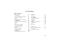
Table of Contents
Safety Summary . . . . . . . . . . . . . . . 1-4
Safety Symbols . . . . . . . . . . . . . . 1-4
Maximum Overvoltage Limitations . . . 1-5
Probes and Test Leads . . . . . . . . . 1-6
Operation . . . . . . . . . . . . . . . . . . . 1-7
Terminals, Shutter, & Test Leads . . . 1-7
Function Switch . . . . . . . . . . . . . . 1-8
Function Keys . . . . . . . . . . . . . . . 1-9
Function Keys/Function Switch Matrix . . 1-12
Display . . . . . . . . . . . . . . . . . . . 1-13
Audio . . . . . . . . . . . . . . . . . . . . 1-13
Calibration and Adjustment . . . . . . . . 1-14
Required Test Equipment . . . . . . . . 1-14
Calibration Procedure . . . . . . . . . . 1-14
Maintenance . . . . . . . . . . . . . . . . . 1-15
Battery Replacement . . . . . . . . . . . 1-15
Fuse Replacement . . . . . . . . . . . . 1-15
Troubleshooting . . . . . . . . . . . . . . 1-16
Cleaning . . . . . . . . . . . . . . . . . . 1-16
Replaceable Parts/Accessories . . . . . 1-16
Specifications . . . . . . . . . . . . . . . . 1-17
General . . . . . . . . . . . . . . . . . . . 1-17
DC Voltage . . . . . . . . . . . . . . . . . 1-17
AC Voltage . . . . . . . . . . . . . . . . 1-17
AC + DC Voltage . . . . . . . . . . . . . 1-18
DC Current, AC Current . . . . . . . . . 1-18
Resistance . . . . . . . . . . . . . . . . . 1-19
Continuity . . . . . . . . . . . . . . . . . . 1-19
Diode . . . . . . . . . . . . . . . . . . . . 1-19
Frequency (AC Coupled) . . . . . . . . . 1-19
Temperature . . . . . . . . . . . . . . . . 1-20
dBm . . . . . . . . . . . . . . . . . . . . . 1-20
Adjustments . . . . . . . . . . . . . . . . . 6-1
Calibration Table . . . . . . . . . . . . . . . 6-2
Replaceable Parts/Accessories . . . . . . 6-4
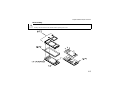
Disassembly . . . . . . . . . . . . . . . . 6-5
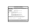
Declaration of Conformity
1-3

Safety Summary
The CAUTIONS and WARNINGS which appear on the following pages must be followed to
ensure operator safety and to retain the operating condition of the Multimeter.
1. Do not use this product beyond its specifications or for uses not intended for this product
as identified by the product functions, ranges, and hazards as indicted below.
2. To minimize possible electric shock hazard condition, connect only two leads at any one
time to any of the multimeter terminals.
3. To prevent possible electric shock hazard condition when using the current function, do not
leave one probe connected to the circuit under test and the other probe disconnected,
exposed, and readily accessible (touchable).
Safety Symbols
Indicates the operator must refer to an explanation in this manual.
Indicates terminals at which dangerous voltages may exist.
WARNING
TO AVOID ELECTRICAL SHOCK or damage to the multimeter, do not apply more than
±1000 Vdc or 1000 Vrms between any terminal and earth ground. Use caution when working with
voltages above 60 Vdc or 42 Vpeak. Ensure test leads are in good condition.
WARNING
POSSIBLE ELECTRICAL SHOCK. Do not make measurements if the case is damaged or the
rear cover is removed. Remove all electrical inputs before removing the rear cover.
WARNING
POSSIBLE ELECTRICAL SHOCK or FIRE HAZARD. Do not expose this multimeter to rain or
moisture. Do not operate the multimeter in the presence of flammable gases or fumes.
1-4

WARNING
POSSIBLE ELECTRICAL SHOCK. Calibration and performance tests are to be performed by
qualified personnel only. Do not attempt calibration or test procedures unless qualified to do so.
CAUTION
To avoid damage to the multimeter for inputs above 250 Vdc or Vac, disconnect the test leads
before changing functions. Do not exceed the maximum input limits.
Maximum Overvoltage Limitations (AC and DC Voltage Functions)
1000V
MAX indicates the maximum voltage between input terminals and earth is ± 1000 V (dc or ac rms).
Do not use the multimeter on any ACV circuit where the maximum impulse overvoltage may
be more than 4000Vpk or any DCV circuit where the maximum impulse overvoltage may be
more than 2500Vpk between the COM and VOLT terminals. Excessive impulse overvoltage
can damage the multimeter voltage functions. Do not measure branch circuits (CAT II) over
600V to earth or service panel circuits (CAT III) over 300V to earth.
Safety Summary
1-5

Function Maximum Operating Input
10 A
± 10 A (dc or ac rms) / 600 V
mA or µA ± 500 mA (dc or ac rms) / 250 V
Resistance, Diode Test,
Temperature, Continuity
500 V (dc or ac rms)
Frequency
(10 Hz to 9.999 kHz)
(9 kHz to 200 kHz)
500 Vrms
100 Vrms
V
± 1000 Vdc or 750 Vrms
Probes and Test Leads
1. Always inspect probes before use. Do not use test leads whose insulation has cuts,
cracks, or other damage that may result in reduced electric shock protection.
2. Keep insulation surface clean between the probe tip connector and the finger guards.
3. If probes other than the ones specified are to be used with the multimeter, be sure the
probes and their leads are rated for the voltage and current to which they will be subjected.
Do not exceed the voltage ratings for the multimeter.
4. Probes supplied with this multimeter are rated for use up to 1000Vrms or Vdc.
Safety Summary
1-6

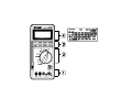
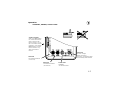
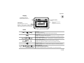
Operation
Terminals, Shutter, & Test Leads
RED LEAD
Current Measurements
(0 A to 10 A)
RED LEAD
Current Measurements
(0 to 400 mA)
BLACK LEAD
COMMON
ALL Measurements
RED LEAD
DC & AC Voltage,
Diode, Resistance,
Frequency, Temperature, dBm
and Continuity Measurements
SAFETY SHUTTER
Slide up to open shutters
for current measurement
inputs. Must have the
function switch in one of
the Current Measurement
positions to open shutter.
Close shutter to change
function switch to any
other measurement
function.
1-7

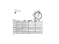
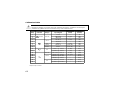
Function Switch
Switch
Position
Display
10A
DC Current
(1 mA to 10 A)
AC Current
(1 mA to 10 A)
500 mA
DC Current
(10 µA to 0.5 A)
AC Current
(10 µA to 0.5 A)
50 mA
DC Current
(1 µA to 0.05 A)
AC Current
(1 µA to 0.05 A)
500 µA
DC Current
(0.01 µA to 0.5 mA)
AC Current
(0.01 µA to 0.5 mA)
Diode Test Auto Diode Test
Ω
Resistance
( 0.01 Ω to 50 MΩ)
Continuity
(alarm at < 100 Ω)
Temperature in °F
(-112° F to 302° F)
Temperature in °C
(-80° C to 150° C)
mV
DC Millivolts
(10 µV to 500 mV)
V
DC Volts
(100 µV to 1000 V)
AC + DC Volts
(1 mV to 750 V)
V
AC Volts
(1 mV to 750 V)
Frequency
(10 Hz to 200 kHz)
Frequency and Volts
1
(10 Hz to 200 kHz)
dBm
(-59.94 dBm to 62.22 dBm)
1
Voltage and frequency readings alternate on display
Operation
1-8

Function Keys
Power
Automatic power off after 30 minutes. Alarm sounds 30 seconds before automatic power off.
Press any key or change any function to cancel automatic power off. Defeat automatic power
off by holding key for 2 seconds while applying power.
Relative/Percent
Press Action Main Display Secondary Display
Makes the displayed measurement
the reference
Each measured value relative to
the reference value (difference)
Range
Calculates the percentage change
from the reference
Each measured value as a
percent change of the reference
value
Range
Cancels the Relative/% function Measurement value Range
Perform a zero adjust when using the 500 Ω range and displayed value is less than 99 by shorting the test
leads and pressing this key. Cycle power to erase the stored zero adjustment.
Operation
1-9

Minimum/Maximum
1
Press Action Main Display Secondary Display
2
Begin recording of min, max, and avg
3
values
Each measured value Elapsed time
Display recorded maximum Maximum measurement Time of Maximum
Display recorded minimum Minimum measurement Time of Minimum
Display recorded average Calculated average Elapsed time
Display last recorded measurement Latest measurement Elapsed time
Pause recording of minimum and
maximum values
Last measured value Total elapsed time
Resume recording of minimum and
maximum values
Each measured value Elapsed time
Press and hold 1 second to cancel - -
1
Automatic power off is disabled when Min/Max is selected.
2
Time is recorded and displayed in minutes and seconds up to 99’ 59". After 99’ 59" time is recorded and
displayed in minutes up to the maximum recording time of 1999 minutes. Recording will stop at the
maximum time.
3
Average is computed from all readings during elapsed time.
Average
Press Action Main Display Secondary Display
Makes the displayed measurement the
average of the last eight measurements
Average value of last eight
measurements
Range
Disables the averaging of measurements Each measurement Range
Operation
1-10

Hold/Auto-Hold
Press Action Main Display Secondary Display
Holds the measurement value in the
display
Measurement value when
hold pressed
Range
Enters Auto-Hold function
1
Input value Range
Cancels Hold function Measurement value Range
1
Auto-Hold Operation. When measurement becomes stable, multimeter will beep and save the
stable reading. Removing probe from measurement circuit will display and hold the last stable reading.
Range
Press Action Main Display Secondary Display
Changes from auto-ranging to manual
ranging
Measurement value Range
Change manual range UP once with
each keypress
1
Measurement value Range
Returns to auto-ranging when key is held
for 1 second
Measurement value Range
1
When upper range is reached, the sequence begins again at the lowest range.
Select
Press this key to use the functions indicated in yellow on the multimeter. See table on page 1- 8.
Hold this key to test display when turning meter on.
Operation
1-11

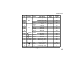
Function Keys and Function Switch Matrix
Function Relative
%
(Percent)
Min/Max
3
Average Data Hold Auto-Hold Range
µA, mA, 10A
••••••
µA, mA, 10A
••••••
•• • • •
•
Ω
•
1
••••••
•
°F, °C
•• •
mV
•• • • •
V
•••••••
••
V
•••••••
Hz Hz+V
••
2
dBm
••
1
Invokes zero adjust when display is less than 99.
2
Changes input attenuator, frequency is always auto range.
3
Secondary display shows elapsed time (in seconds and minutes).
Operation
1-12

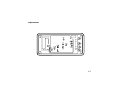
Display
Audio
Power on
First beep at power on.
Second beep when beginning to make measurements.
Single beep
Indicates any valid function key press.
Indicates a new High or Low value recorded when in Min/Max function.
Steady repeating beep
Indicates when measurement is steady when using Auto-Hold function.
Rapid repeating beeps
Indicates wrong input terminals used for function selected.
Indicates an overload condition at the measurement terminals.
Continuous tone
Indicates a resistance of < 100 Ω when using the Continuity function.
Auto Power Off
Pairs of beeps for 30 seconds.
Long beep just before power off.
Cancel by changing function switch position or pressing any key.
Low Battery indicator
Replace batteries when on.
Secondary Display
Shows:
Range (most functions)
except for
Elapsed time (Min/Max)
Main Display
(Not all annunciators shown)
Number of digits is set by range and function
Displays O.L to indicate an overload condition
Entire display flashes if input overvoltage
Operation
1-13

Calibration and Adjustment
Required Test Equipment
The source used for the calibration should have an output accuracy as good or better than
that listed in the specifications.
Calibration Procedure
Environmental range for calibration: 23° C ± 5° C, < 80% RH
Calibration interval: 6 Months
1 Disconnect all inputs from the multimeter and open the case as described on page 6-5.
2 Install new batteries (described below) and close the cover. Turn the multimeter on and allow a
30 minute warm-up. Open the case.
3 Set the multimeter function and range and the source output to the values specified at each step
in the calibration table on page 6-2.
4 When appropriate, make the adjustments indicated in the calibration table to bring the multimeter
display within the limits.
CAUTION
Dangerous voltages are present during the calibration procedure. Calibration should only be
performed by qualified service technicians Use a non-conductive adjustment tool.
1-14

Maintenance
Operator protection from electric shock hazard is provided by a double insulated enclosure.
Refer to pages 1-4 and 1-5 for maximum voltage specifications. When servicing, use only
specified replacement parts.
Battery Replacement
Replace the battery when the symbol appears in the display or before calibration. Replace
both batteries at the same time. Use high-quality type AA alkaline (IEC LR6) batteries.
Remove the batteries if the multimeter is to be stored for extended periods of time. Refer to
the disassembly drawing on page 6-5.
Fuse Replacement
Fuse locations are shown in the diagram on page 6-5. Fuses are listed in the replaceable part
list on page 6-4.
CAUTION
For continued protection use only the specified manufacturers part number or HP part number
fuse for replacement purposes.
1-15

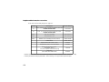
Troubleshooting
Problem Possible Cause Suggested Action
Unit won’t turn on Dead Batteries
Replace batteries
Unit won’t turn off Input limit exceeded
Remove test leads and press any key to reset.
Display flashes and Rapid
beeps
Input limit exceeded
Remove test leads and press any key to reset.
Battery Annunciator on Low battery voltage
Replace batteries
Unable to measure current
10 A or mA - µA
Blown input protection fuse
Replace fuse(s)
Cleaning
Wipe instrument with a soft rag dampened with soap and water. Do not immerse in water.
Do not use chemical cleansers or solvents.
Replaceable Parts/Accessories
Refer to the disassembly diagram on page 6-5.
Maintenance
1-16

Specifications
Calibration period: six months minimum. Specifications apply at 23°C ± 5°C, < 80% RH
Accuracy = ± (% of reading + number of digits)
Temperature Coefficient = Accuracy 0.1/° C (0° C to 18° C; 28° C to 55° C)
General
Do not expose product to moisture or rain. Do not use product in flammable atmosphere.
Operating Temperature: 0° to 40°C / 80% RH max (no condensation).
Storage Temperature: -25°C to 60°C / 20% to 70°C RH (no condensation).
Display reading rate: Approximately 2 — 4 times/second
Display rate for frequency measurements: Approximately 1 times/second
Battery life: Approximately 120 hours on DCV
DC Voltage
Range Resolution Accuracy Input Resistance
500 mV
10 µV
± (0.05% + 2)
> 1000 MΩ
5 V
100 µV
11 MΩ (nominal)
50 V 1 mV
10 MΩ (nominal)
500 V 10 mV
1000 V 100 mV
Normal Mode Rejection Ratio: (NMR) > 60 dB @ 50 or 60 Hz
Effective Common Mode Rejection Ratio (CMR) 1 kΩ imbalance: > 120 dB @ 50 or 60 Hz
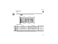
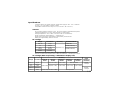
AC Voltage (RMS responding, calibrated to display rms)
Range Resolution
Accuracy
Input
Impedance
(nominal)
20 Hz to
50 Hz
50 Hz to
10 kHz
10 kHz to
30 kHz
30 kHz to
50 kHZ
50 kHz to
100 kHz
500 mV
10 µV
± (1% + 30)
± (0.7% +30) ± (2% + 50)
Not Specified
11 M Ω
< 50 pF
5 V
100 µV
± (0.5% + 30) ± (1% + 40) ± (2% + 70) ± (3% + 300)50 V 1 mV
10 M Ω
< 50 pF
500 V 10 mV
750 V 100 V
± (1% + 30) 20 Hz to 1 kHz
Not Specified
1-17

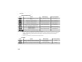
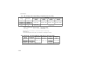
AC + DC Voltage (rms responding, computed from acV, dcV)
Range Resolution
Accuracy
DC, 20 Hz to
10 kHz
DC, 10 kHz to
30 kHz
DC, 30 kHz to
50 kHZ
DC, 50 kHz to
100 kHz
5 V 1 mV
± (1% + 30) ± (1.2% + 40) ± (2.5% + 70) ± (3.5% + 300)
50 V 10 mV
500 V 100 mV
750 V 1 V
± (1% + 30)
DC, 20 Hz to 1 kHz
Not Specified
Measurement range:
500 mV to 500 V ranges 20 Hz to 30 kHz 5% to 100% of range
30 kHz to 100 kHz 10% to 100% of range
750 V range 75 V to 750 V
Response time: < 2 seconds for AC, 5 seconds for AC+DC on fixed range
Crest factor: <3
Common Mode Rejection Ratio (CMR) 1 k Ω imbalance: > 60 dB @ DC to 60 Hz
DC Current, AC Current (40 Hz to 1 kHz), 5% to 100% of range
Range Resolution
DC Current
Accuracy
AC Current
Accuracy
Input
Resistance
Maximum
Input
500 µA
10 nA
± (0.3% + 2)
± (1% + 20)
< 1050 Ω
0.5 A (fused)50 mA
1 µA< 12 Ω
500 mA
10 µA < 2.5 Ω
10 A 1 mA
± (0.7% + 2) < 0.05 Ω
15 A (fused)
Specifications
1-18

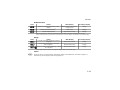
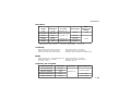
Resistance
Range Resolution Accuracy Test Current
Max
Open Circuit
Voltage
500 Ω 10 mΩ± (0.06% + 2)
1
< 800 µA
< 5.5 V
5.0 kΩ 100 mΩ
± (0.06% + 2) 50 kΩ 1Ω < 80 µA
< 2.2 V
500 kΩ 10 Ω < 15 µA
5.0 MΩ 100 Ω ± (0.5% + 1) < 1.5 µA
50 MΩ 1 kΩ ± (1.0% + 2)
< 150 nA
1
After zero adjust of input leads. Zero adjust range up to 0.99 Ω.
Response time: 500 Ω to 500 kΩ — < 2 seconds, 5 MΩ to 50 MΩ — < 10 seconds.
Continuity
Measurement Current: 0.8 mA maximum Open circuit voltage: < 5.5 Vpeak
Displayed resistance: 0 Ω to 499.99 Ω Input protection: 500 Vrms (sinewave)
Alarm: Tone when input < 100 Ω ± 50 Ω Resolution: 10 mΩ (<100 mSec response time)
Diode
Measurement current: +1.0 mA nominal @ 0.6 V Open circuit voltage: < 5.5 Vpeak
Displayed Voltage: 0 V to 4.999 V Input protection: 500 Vrms (sinewave)
Accuracy: ± (1% + 2) Resolution: 100 µV
Frequency (AC Coupled)
Frequency Range Resolution Accuracy Input Voltage (rms)
10 Hz to 99.99 Hz 0.01 Hz
± (0.05% + 1)
0.45 mV to 500 V90 Hz to 999.0 Hz 0.1 Hz
900 Hz to 9.999 Hz 1 Hz
9.00 kHz to 99.99 kHz 10 Hz .7 V to 100 V
90 kHz to 200 kHz 100 Hz 1.5 V to 100 V
Specifications
1-19

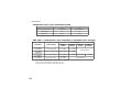
Temperature (5 kΩ @ 25°C Thermistor probe)
°C °F
Measurement Range
-80° to 150° -112° to 302°
Resolution
0.1° 0.1°
Accuracy
1
± 0.2°± 0.4°
1
Accuracy does not include 5 k Ω Thermistor error
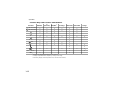
dBm 600 Ω 1 mW reference (rms responding, computed from AC Voltage)
Input dBm Input Voltage
Accuracy
20 Hz to
10 kHz
10 kHz to
30 kHz
30 kHz to
50 kHz
50 kHz to
100 kHz
-29.82 dBm to
-23.80 dBm
25 mV to 50 mV
± 0.2 dBm ± 0.50 dBm
Not specified
-23.80 dBm to
-3.80 dBm
50 mV to 499.99 mV
± 0.15 dBm ± 0.30 dBm
-3.80 dBm to
55.28 dBm
0.5 V to 450.00 V
± 0.10 dBm ± 0.20 dBm
± 0.5 dBm ± 1.00 dBm
55.28 dBm to
59.72 dBm
450 V to 750 V
± 0.15 dBm
to 1kHz
Not specified
Dynamic range: -59.94 dBm to 59.72 dBm (0.8 mV to 750 V),
Accuracy not specified below -29.82 dBm (25 mV)
Display reads OL (overload) outside dynamic range
Specifications
1-20
Page is loading ...
Page is loading ...
Page is loading ...
Page is loading ...
Page is loading ...
Page is loading ...
Page is loading ...
-
 1
1
-
 2
2
-
 3
3
-
 4
4
-
 5
5
-
 6
6
-
 7
7
-
 8
8
-
 9
9
-
 10
10
-
 11
11
-
 12
12
-
 13
13
-
 14
14
-
 15
15
-
 16
16
-
 17
17
-
 18
18
-
 19
19
-
 20
20
-
 21
21
-
 22
22
-
 23
23
-
 24
24
-
 25
25
-
 26
26
-
 27
27


HP Video Game Keyboard 00974-90002 User manual
- Category
- Measuring, testing & control
- Type
- User manual
- This manual is also suitable for
Ask a question and I''ll find the answer in the document
Finding information in a document is now easier with AI