
INSTRUCTION MANUAL
MODEL 200AH
NITROGEN OXIDES ANALYZER
©TELEDYNE INSTRUMENTS
ADVANCED POLLUTION INSTRUMENTATION DIVISION
(T-API)
9480 CARROLL PARK DRIVE
SAN DIEGO, CA 92121-5201
TOLL-FREE: 800-324-5190
FAX: 858-657-9816
TEL: 858-657-9800
E-MAIL: [email protected]
WEB SITE: www.teledyne-api.com
01620 REV. G2
DCN 5333
Copyright 2006 T-API Inc.
03 March 2009
PRINT DATE: 03 March 2009

THIS PAGE IS INTENTIONALLY LEFT BLANK

Teledyne API Model 200AH NO
X
Analyzer Instruction Manual, 06492, Rev. G2
i
SAFETY MESSAGES
Your safety and the safety of others is very important. We have provided many important safety messages
in this manual. Please read these messages carefully.
A safety message alerts you to potential hazards that could hurt you or others. Each safety message is
associated with a safety alert symbol. These symbols are found in the manual and inside the instrument.
The definition of these symbols is described below:
GENERAL WARNING/CAUTION: Refer to the instructions for details on the
specific danger.
CAUTION: Hot Surface Warning
CAUTION: Electrical Shock Hazard
Technician Symbol: All operations marked with this symbol are to be performed
by qualified maintenance personnel only.
Electrical Ground: This symbol inside the instrument marks the central safety
grounding point for the instrument.
CAUTION
The analyzer should only be used for the purpose
and in the manner described in this manual.
If you use the analyzer in a manner other than that for which
it was intended, unpredictable behavior could ensue with
possible hazardous consequences.

Teledyne API Model 200AH NO
X
Analyzer Instruction Manual, 06492, Rev. G2
ii
THIS PAGE IS INTENTIONALLY LEFT BLANK

Teledyne API Model 200AH NO
X
Analyzer Instruction Manual, 06492, Rev. G2
iii
Table of Contents
SAFETY MESSAGES ........................................................................................... I
LIST OF TABLES.............................................................................................. VIII
1. HOW TO USE THIS MANUAL...................................................................... 1-1
2. GETTING STARTED..................................................................................... 2-1
2.1. UNPACKING.................................................................................................................... 2-1
2.2.
ELECTRICAL AND PNEUMATIC CONNECTIONS .................................................................... 2-1
2.3.
INITIAL OPERATION ......................................................................................................... 2-7
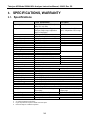
3. SPECIFICATIONS, WARRANTY.................................................................. 3-1
3.1. SPECIFICATIONS ............................................................................................................. 3-1
3.2. WARRANTY .................................................................................................................... 3-2
4. THE M200AH NOX ANALYZER ................................................................... 4-1
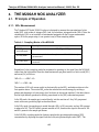
4.1. PRINCIPLE OF OPERATION...............................................................................................4-1
4.1.1. NO
X
Measurement................................................................................................. 4-1
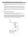
4.1.2. Oxygen Measurement (Option) ............................................................................. 4-2
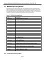
4.2. OPERATION SUMMARY ....................................................................................................4-5
4.2.1. NO
X
Sensor Module, Reaction Cell, Detector........................................................ 4-5
4.2.2. Oxygen Sensor Module (Option)........................................................................... 4-5
4.2.3. Pneumatic Sensor Board....................................................................................... 4-6
4.2.4. Computer Hardware and Software........................................................................ 4-6
4.2.5. V/F Board.............................................................................................................. 4-7
4.2.6. Front Panel............................................................................................................ 4-7
4.2.7. Power Supply Module............................................................................................ 4-8
4.2.8. Pump, Valves, Pneumatic System......................................................................... 4-8
4.2.9. Ozone Generator................................................................................................. 4-11
4.2.10. NO
2
- NO Converter ..........................................................................................4-11
5. SOFTWARE FEATURES.............................................................................. 5-1
5.1. INDEX TO FRONT PANEL MENUS....................................................................................... 5-1
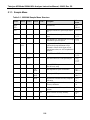
5.1.1. Sample Menu ........................................................................................................ 5-6
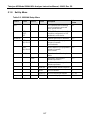
5.1.2. Set-Up Menu ......................................................................................................... 5-7
5.2.
SAMPLE MODE ............................................................................................................. 5-11
5.2.1. Test Functions.....................................................................................................5-11
5.2.2. CAL, CALS, CALZ, Calibration Functions............................................................ 5-15
5.3. SET-UP MODE.............................................................................................................. 5-17
5.3.1. Configuration Information (CFG) ......................................................................... 5-17
5.3.2. Automatic Calibration (AutoCal) .......................................................................... 5-17
5.3.3. Data Acquisition System (DAS)...........................................................................5-18

Teledyne API Model 200AH NO
X
Analyzer Instruction Manual, 06492, Rev. G2
iv
5.3.4. Range Menu........................................................................................................ 5-20
5.3.5. Password Enable................................................................................................. 5-23
5.3.6. Time of Day Clock............................................................................................... 5-23
5.3.7. Diagnostic Mode.................................................................................................. 5-23
5.3.8. Communications Menu........................................................................................ 5-24
5.3.9. Variables Menu (VARS) ......................................................................................5-24
5.4. M200AH OPERATING MODES........................................................................................ 5-25
5.4.1. NO/NO
x
/NO
2
Switching Mode.............................................................................. 5-25
5.4.2. NO
X
Only Mode................................................................................................... 5-26
5.4.3. NO Only Mode.....................................................................................................5-26
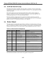
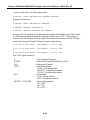
5.5. 4-20 MA CURRENT LOOP .............................................................................................. 5-27
5.6. STATUS OUTPUT........................................................................................................... 5-27
5.7.
RS-232 INTERFACE......................................................................................................5-28
5.7.1. Setting up the RS-232 Interface .......................................................................... 5-28
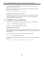
5.7.2. Command Summary............................................................................................ 5-31
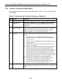
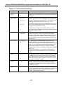
5.7.3. TEST Commands and Messages........................................................................5-35
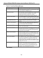
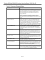
5.7.4. WARNING Commands and Messages................................................................ 5-36
5.7.5. CALIBRATION Commands and Messages.........................................................5-37
5.7.6. DIAGNOSTIC Commands and Messages........................................................... 5-38
5.7.7. DAS Commands and Messages.......................................................................... 5-39
5.7.8. VARIABLES Commands and Messages.............................................................5-41
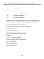
6. OPTIONAL HARDWARE AND SOFTWARE................................................ 6-1
6.1. RACK MOUNT OPTIONS...................................................................................................6-1
6.2. ZERO/SPAN VALVES OPTION ...........................................................................................6-2
6.2.1. Autocal - Setup Zero/Span Valves......................................................................... 6-3
6.3. OXYGEN SENSOR OPTION ............................................................................................... 6-4
6.4. ISOLATED 4-20 MA CURRENT LOOP OPTION .....................................................................6-5
6.5. MOLYBDENUM CONVERTER OPTION ................................................................................. 6-5
6.6. EXTERNAL DESICCANT CANISTER OPTION ........................................................................ 6-5
6.7.
ALTERNATE BYPASS FLOW ORIFICE OPTION.....................................................................6-5
6.8.
M501 EXTERNAL CONVERTER OPTION............................................................................. 6-5
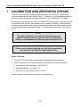
7. CALIBRATION AND ZERO/SPAN CHECKS ............................................... 7-1
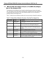
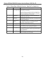
7.1. MANUAL NO
X
ZERO/SPAN CHECK OR CAL WITH ZERO/SPAN GAS IN THE SAMPLE PORT...... 7-3
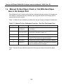
7.2.
MANUAL O
2
ZERO/SPAN CHECK OR CAL WITH ZERO/SPAN GAS IN THE SAMPLE PORT ........ 7-6
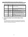
7.3. MANUAL ZERO/SPAN CHECK WITH ZERO/SPAN VALVES OPTION......................................... 7-7
7.4. DYNAMIC ZERO/SPAN CALIBRATION USING AUTOCAL........................................................ 7-9
7.5.
USE OF ZERO/SPAN VALVES WITH REMOTE CONTACT CLOSURE ...................................... 7-10
7.6. NO ONLY MODE CALIBRATION....................................................................................... 7-11
7.7.
NO
X
ONLY MODE CALIBRATION ..................................................................................... 7-11
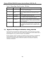
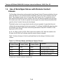
7.8. CALIBRATION REQUIREMENTS FOR AUTORANGE OR REMOTE RANGE................................ 7-11
7.9.
CALIBRATION REQUIREMENTS FOR INDEPENDENT RANGE ................................................ 7-12
7.10.
CALIBRATION QUALITY ................................................................................................ 7-12
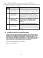
7.11.
CONVERTER EFFICIENCY COMPENSATION..................................................................... 7-13
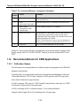
7.12.
RECOMMENDATIONS FOR CEM APPLICATIONS.............................................................. 7-14

Teledyne API Model 200AH NO
X
Analyzer Instruction Manual, 06492, Rev. G2
v
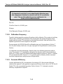
7.12.1. Calibration Gasses............................................................................................ 7-14
7.12.2. Calibration Frequency .......................................................................................7-15
7.12.3. Converter Efficiency .......................................................................................... 7-15
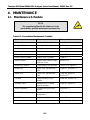
8. MAINTENANCE ............................................................................................ 8-1
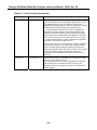
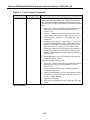
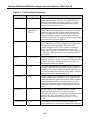
8.1. MAINTENANCE SCHEDULE ............................................................................................... 8-1
8.2. REPLACING THE SAMPLE PARTICULATE FILTER ................................................................. 8-2
8.3. REPLACING THE CONVERTER........................................................................................... 8-4
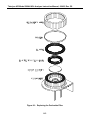
8.4. CLEANING THE REACTION CELL ....................................................................................... 8-6
8.5. PNEUMATIC LINE INSPECTION .......................................................................................... 8-9
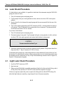
8.6. LEAK CHECK PROCEDURE.............................................................................................8-13
8.7. LIGHT LEAK CHECK PROCEDURE.................................................................................... 8-13
8.8. PROM REPLACEMENT PROCEDURE ................................................................................ 8-14
9. TROUBLESHOOTING AND ADJUSTMENTS.............................................. 9-1
9.1.
OPERATION VERIFICATION - DIAGNOSTIC TECHNIQUES ...................................................... 9-2
9.1.1. Fault Diagnosis with TEST Variables .................................................................... 9-2
9.1.2. Fault Diagnosis with WARNING Messages........................................................... 9-8
9.1.3. Fault Diagnosis using DIAGNOSTIC Mode.........................................................9-10
9.1.4. M200AH Internal Variables.................................................................................. 9-17
9.1.5. Test Channel Analog Output ............................................................................... 9-19
9.1.6. Factory Calibration Procedure.............................................................................9-20
9.2. PERFORMANCE PROBLEMS............................................................................................ 9-24
9.2.1. AC Power Check................................................................................................. 9-24
9.2.2. Flow Check.......................................................................................................... 9-25
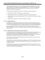
9.2.3. No Response to Sample Gas..............................................................................9-25
9.2.4. Negative Output................................................................................................... 9-26
9.2.5. Excessive Noise.................................................................................................. 9-26
9.2.6. Unstable Span..................................................................................................... 9-27
9.2.7. Unstable Zero......................................................................................................9-28
9.2.8. Inability to Span...................................................................................................9-28
9.2.9. Inability to Zero....................................................................................................9-28
9.2.10. Non-Linear Response........................................................................................ 9-29
9.2.11. Slow Response.................................................................................................. 9-30
9.2.12. Analog Output Doesn't Agree With Display Concentration................................ 9-30
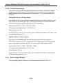
9.3. SUBSYSTEM TROUBLESHOOTING AND ADJUSTMENTS....................................................... 9-31
9.3.1. Computer, Display, Keyboard.............................................................................. 9-31
9.3.2. RS-232 Communications..................................................................................... 9-34
9.3.3. Voltage/Frequency (V/F) Board...........................................................................9-37
9.3.4. Status/Temp Board.............................................................................................. 9-43
9.3.5. Power Supply Module.......................................................................................... 9-45
9.3.6. Ozone Generator................................................................................................. 9-49
9.3.7. Flow/Pressure Sensor......................................................................................... 9-53
9.3.8. NO
X
Sensor Module ............................................................................................ 9-58
9.3.9. Z/S Valves........................................................................................................... 9-63
9.3.10. Pneumatic System............................................................................................. 9-64


Teledyne API Model 200AH NO
X
Analyzer Instruction Manual, 06492, Rev. G2
vii
LIST OF FIGURES
FIGURE 2-1: REMOVAL OF SHIPPING SCREWS & CHECK FOR CORRECT POWER............................2-3
FIGURE 2-2: REAR PANEL.........................................................................................................2-4
FIGURE 2-3: REAR PANEL WITH O
2
OPTION................................................................................ 2-5
FIGURE 2-4: INLET AND EXHAUST VENTING RECOMMENDATIONS.................................................. 2-6
FIGURE 2-5: FRONT PANEL ..................................................................................................... 2-12
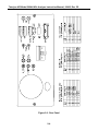
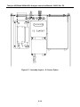
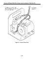
FIGURE 2-6: ASSEMBLY LAYOUT.............................................................................................. 2-13
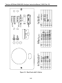
FIGURE 2-7: ASSEMBLY LAYOUT – O
2
SENSOR OPTION............................................................. 2-14
FIGURE 4-1: PARAMAGNETIC SENSOR........................................................................................ 4-3
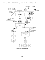
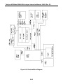
FIGURE 4-2: BLOCK DIAGRAM ................................................................................................... 4-4
FIGURE 4-3: EXTERNAL PUMP PACK........................................................................................4-10
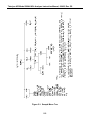
FIGURE 5-1: SAMPLE MENU TREE ............................................................................................. 5-2
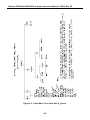
FIGURE 5-2: SETUP MENU TREE ............................................................................................... 5-3
FIGURE 5-3: SETUP MENU TREE- UNITS WITH O
2
SENSOR .......................................................... 5-4
FIGURE 5-4: SETUP MENU TREE – UNITS WITH O
2
SENSOR......................................................... 5-5
FIGURE 8-1: REPLACING THE PARTICULATE FILTER..................................................................... 8-3
FIGURE 8-2: CONVERTER ASSEMBLY ......................................................................................... 8-5
FIGURE 8-3: REACTION CELL ASSEMBLY.................................................................................... 8-7
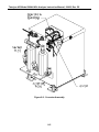
FIGURE 8-4: SAMPLE/BYPASS FLOW CONTROL ASSEMBLY .......................................................... 8-8
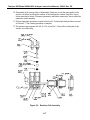
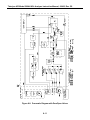
FIGURE 8-5: PNEUMATIC DIAGRAM ..........................................................................................8-10
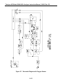
FIGURE 8-6: PNEUMATIC DIAGRAM WITH ZERO/SPAN VALVES.................................................... 8-11
FIGURE 8-7: PNEUMATIC DIAGRAM WITH OXYGEN SENSOR........................................................ 8-12
FIGURE 9-1: SPAN CALIBRATION VOLTAGE............................................................................... 9-23
FIGURE 9-2: CPU BOARD JUMPER SETTINGS........................................................................... 9-33
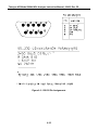
FIGURE 9-3: RS-232 PIN ASSIGNMENTS.................................................................................. 9-35
FIGURE 9-4: V/F BOARD JUMPER SETTINGS............................................................................. 9-42
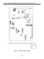
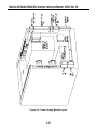
FIGURE 9-5: POWER SUPPLY MODULE LAYOUT ........................................................................ 9-47
FIGURE 9-6: ELECTRICAL BLOCK DIAGRAM............................................................................... 9-48
FIGURE 9-7: OZONE GENERATOR SUBSYSTEM ......................................................................... 9-52
F
IGURE 9-8: FLOW/PRESSURE SENSOR................................................................................... 9-55
FIGURE 9-9: NO
X
SENSOR MODULE ........................................................................................ 9-56
FIGURE 9-10: NO
X
SENSOR MODULE ......................................................................................9-57
F
IGURE 9-11: PMT COOLER SUBSYSTEM ................................................................................ 9-60
F
IGURE 9-12: HIGH VOLTAGE POWER SUPPLY ......................................................................... 9-62

Teledyne API Model 200AH NO
X
Analyzer Instruction Manual, 06492, Rev. G2
viii
LIST OF TABLES
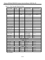
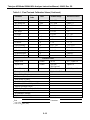
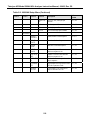
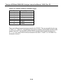
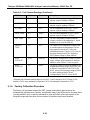
TABLE 2-1: FINAL TEST AND CALIBRATION VALUES ................................................................... 2-15
TABLE 4-1: SAMPLING MODES OF THE M200AH.........................................................................4-1
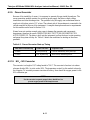
TABLE 4-2: FRONT PANEL STATUS LED'S .................................................................................. 4-8
T
ABLE 4-3: OZONE GENERATOR START-UP TIMING................................................................... 4-11
T
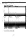
ABLE 5-1: M200AH SAMPLE MENU STRUCTURE....................................................................... 5-6
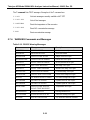
TABLE 5-2: M200AH SETUP MENU ........................................................................................... 5-7
TABLE 5-3: M200AH SETUP MENU ........................................................................................... 5-9
TABLE 5-4: M200AH SETUP MENU ......................................................................................... 5-10
TABLE 5-5: DAS DATA CHANNEL EDITING................................................................................ 5-19
TABLE 5-6: CALIBRATE, SETUP PASSWORDS ............................................................................ 5-23
TABLE 5-7: M200AH OPERATING MODES................................................................................ 5-25
TABLE 5-8: STATUS OUTPUT PIN ASSIGNMENTS ....................................................................... 5-27
TABLE 5-9: RS-232 PORT SETUP - FRONT PANEL ....................................................................5-29
TABLE 5-10: RS-232 SWITCHING FROM TERMINAL MODE TO COMPUTER MODE.........................5-30
TABLE 5-11: RS-232 TERMINAL MODE EDITING KEYS............................................................... 5-31
TABLE 5-12: RS-232 COMMAND SUMMARY.............................................................................. 5-32
TABLE 5-13: RS-232 COMMAND SUMMARY.............................................................................. 5-33
TABLE 5-14: RS-232 INTERFACE COMMAND TYPES.................................................................. 5-34
TABLE 5-15: RS-232 TEST MESSAGES.................................................................................... 5-35
TABLE 5-16: RS-232 WARNING MESSAGES ............................................................................. 5-36
TABLE 5-17: RS-232 CALIBRATION MESSAGES ........................................................................ 5-37
TABLE 5-18: RS-232 CALIBRATION COMMANDS .......................................................................5-38
TABLE 5-19: RS-232 DIAGNOSTIC COMMAND SUMMARY........................................................... 5-39
TABLE 6-1: ZERO/SPAN VALVE OPERATION................................................................................ 6-2
TABLE 6-2: SETUP AUTOMATIC ZERO/SPAN CHECKING OR CALIBRATION ...................................... 6-3
TABLE 6-3: ACTION OF MODE FIELD IN AUTOCAL ...................................................................... 6-4
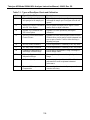
TABLE 7-1: TYPES OF ZERO/SPAN CHECK AND CALIBRATION....................................................... 7-2
TABLE 7-2: MANUAL ZERO CALIBRATION PROCEDURE - ZERO GAS THRU SAMPLE PORT ............... 7-3
T
ABLE 7-3: ENTER EXPECTED SPAN GAS CONCENTRATIONS PROCEDURE.................................... 7-4
TABLE 7-4: MANUAL SPAN CALIBRATION PROCEDURE - SPAN GAS THRU SAMPLE PORT................ 7-5
TABLE 7-5: MANUAL O
2
ZERO CALIBRATION PROCEDURE - ZERO GAS THRU SAMPLE PORT........... 7-6
T
ABLE 7-6: MANUAL O
2
SPAN CALIBRATION PROCEDURE - SPAN GAS THRU SAMPLE PORT........... 7-7
T
ABLE 7-7: MANUAL ZERO CHECK PROCEDURE - Z/S VALVES.....................................................7-8
TABLE 7-8: MANUAL SPAN CHECK PROCEDURE - Z/S VALVES .....................................................7-9
TABLE 7-9: Z/S VALVE MODES WITH REMOTE CONTACT CLOSURE............................................. 7-10
TABLE 7-10: CALIBRATION REQUIREMENTS FOR AUTORANGE OR REMOTE RANGE...................... 7-12
T
ABLE 7-11: CALIBRATION QUALITY CHECK.............................................................................. 7-13
TABLE 7-12: CONVERTER EFFICIENCY - AUTOMATIC CALCULATION ............................................ 7-14
T
ABLE 8-1: PREVENTATIVE MAINTENANCE SCHEDULE................................................................. 8-1
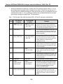
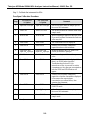
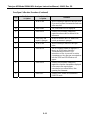
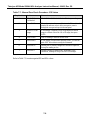
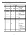
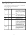
TABLE 9-1: TEST FUNCTIONS .................................................................................................... 9-3
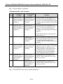
TABLE 9-2: FRONT PANEL WARNING MESSAGES......................................................................... 9-9
TABLE 9-3: SUMMARY OF DIAGNOSTIC MODES ......................................................................... 9-11

Teledyne API Model 200AH NO
X
Analyzer Instruction Manual, 06492, Rev. G2
ix
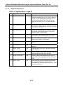
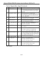
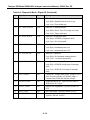
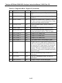
TABLE 9-4: DIAGNOSTIC MODE - SIGNAL I/O ............................................................................ 9-12
TABLE 9-5: MODEL 200AH VARIABLES .................................................................................... 9-18
TABLE 9-6: TEST CHANNEL READINGS.....................................................................................9-19
T
ABLE 9-7: MOTHERBOARD JUMPER SETTINGS......................................................................... 9-39
T
ABLE 9-8: V/F BOARD SWITCH SETTINGS............................................................................... 9-39
TABLE 9-9: POWER SUPPLY MODULE SUBASSEMBLIES.............................................................. 9-46
TABLE 9-10: POWER SUPPLY MODULE LED OPERATION........................................................... 9-49
TABLE 9-11: OZONE GENERATOR CONTROL CONDITIONS.......................................................... 9-50

Teledyne API Model 200AH NO
X
Analyzer Instruction Manual, 06492, Rev. G2
x
THIS PAGE IS INTENTIONALLY LEFT BLANK

Teledyne API Model 200AH NO
X
Analyzer Instruction Manual, 06492, Rev. G2
1-1
1. HOW TO USE THIS MANUAL
The Model 200AH has been designed to produce accurate data, be serviceable, reliable and easy
to use. The M200AH's microprocessor continually checks operating parameters such as
temperature, flow, and critical voltages. The instruments design uses top mounted, modular
components with captive screws to facilitate repair and ease of access. If you encounter any
difficulty refer to the Troubleshooting Section 9 - General Hints.
We recognize that the need for information from this manual changes as time passes. When the
instrument first arrives, it is necessary to get it up and running quickly and verify its correct
operation. As time passes, more detailed information is often required on special configurations,
calibration alternatives and other operational details. Finally there is the need for periodic
maintenance and to quickly troubleshoot problems to assure maximum reliability and data
integrity.
To address these needs, we have created three indexes to the information inside. They are:
Table of Contents:
Outlines the contents of the manual in the order the information is presented. This is a good
overview of the topics covered in the manual. There is also a list of Tables and a list of Figures.
Index to M200AH Front Panel Menus:
The Menu Index briefly describes the front panel menus and refers you to other sections of the
manual that have a detailed explanation of each menu selection.
Troubleshooting Section 9:
The Troubleshooting Section allows you to diagnose and repair the instrument based on
variables in the TEST menu, the results of DIAGNOSTIC tests, and performance faults such as
excessive noise or drift. The troubleshooting section also explains the operation, adjustment,
diagnosis and testing of each instrument subsystem.
If you are unpacking the instrument for the first time, please refer to Getting Started in
Section 2.

Teledyne API Model 200AH NO
X
Analyzer Instruction Manual, 06492, Rev. G2
1-2
THIS PAGE IS INTENTIONALLY LEFT BLANK

Teledyne API Model 200AH NO
X
Analyzer Instruction Manual, 06492, Rev. G2
2-1
2. GETTING STARTED
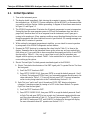
2.1. Unpacking
CAUTION
Your safety and the safety of others is very important. We
have provided many important safety messages in this manual.
Please read these messages carefully.
To avoid personal injury, always use two persons to
lift and carry the Model 200AH.
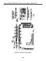
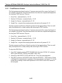
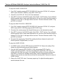
1. Before operation it is necessary to remove the shipping hold-down screws. Remove the
instrument cover, then remove 2 screws as shown in Figure 2-1.
2. Also check for internal shipping damage, and generally inspect the interior of the instrument
to make sure all circuit boards and other components are in good shape.
3. Please check the voltage and frequency label on the serial number tag on the rear panel.
Compare that to your local power before plugging in the Instrument.
2.2. Electrical and Pneumatic Connections
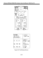
1. Refer to Figure 2-2 to locate the rear panel electrical and pneumatic connections.
2. Attach the pump to the “Exhaust Out” port on the instrument rear panel. The exhaust from
the pump should also be vented to atmospheric pressure.
3. Attach the sample inlet line to the sample inlet port. For initial testing, sample gas can be
calibration gas or stack gas. The pressure of the sample gas at the inlet port should be at
ambient pressure and constant. See Figure 2-4.
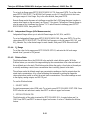
4. If desired, attach the analog output connections to a strip chart recorder and/or datalogger.
Refer to Figure 9-4 - Analog Output Voltage Ranges - for switch settings. Factory default
setting is 0-5 VDC.
5. Connect the power cord to the correct voltage line, then turn to Section 2.3 Initial Operation.

Teledyne API Model 200AH NO
X
Analyzer Instruction Manual, 06492, Rev. G2
2-2
WARNING
Analyzer Exhaust – O
3
Scrubber – Pump Pack
Danger – Analyzer exhaust contains ozone.
Do not defeat the internal zone scrubber. This device must always
be present between the analyzer reaction cell and pump.
Vent pump exhaust to well ventilated area at atmospheric pressure.
FIRE or EXPLOSION HAZARD
If the optional charcoal NO
2
scrubber is used on the exhaust,
charcoal treated with halogen compounds must not be used.
Use only Teledyne API P/N 00596 charcoal.
Wait at least 5 minutes after turning off pump before
removing NO
2
scrubber.
WARNING
Lethal voltages present inside case.
Do not operate with cover off during normal operation.
Before operation check for correct
input voltage and frequency.
Do not operate without proper chassis grounding.
Do not defeat the ground wire on power plug.
Turn off analyzer power before disconnecting
electrical subassemblies.

Teledyne API Model 200AH NO
X
Analyzer Instruction Manual, 06492, Rev. G2
2-3
Figure 2-1: Removal of Shipping Screws & Check for Correct Power

Teledyne API Model 200AH NO
X
Analyzer Instruction Manual, 06492, Rev. G2
2-4
Figure 2-2: Rear Panel

Teledyne API Model 200AH NO
X
Analyzer Instruction Manual, 06492, Rev. G2
2-5
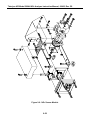
Figure 2-3: Rear Panel with O
2
Option

Teledyne API Model 200AH NO
X
Analyzer Instruction Manual, 06492, Rev. G2
2-6
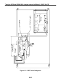
Figure 2-4: Inlet and Exhaust Venting Recommendations
Page is loading ...
Page is loading ...
Page is loading ...
Page is loading ...
Page is loading ...
Page is loading ...
Page is loading ...
Page is loading ...
Page is loading ...
Page is loading ...
Page is loading ...
Page is loading ...
Page is loading ...
Page is loading ...
Page is loading ...
Page is loading ...
Page is loading ...
Page is loading ...
Page is loading ...
Page is loading ...
Page is loading ...
Page is loading ...
Page is loading ...
Page is loading ...
Page is loading ...
Page is loading ...
Page is loading ...
Page is loading ...
Page is loading ...
Page is loading ...
Page is loading ...
Page is loading ...
Page is loading ...
Page is loading ...
Page is loading ...
Page is loading ...
Page is loading ...
Page is loading ...
Page is loading ...
Page is loading ...
Page is loading ...
Page is loading ...
Page is loading ...
Page is loading ...
Page is loading ...
Page is loading ...
Page is loading ...
Page is loading ...
Page is loading ...
Page is loading ...
Page is loading ...
Page is loading ...
Page is loading ...
Page is loading ...
Page is loading ...
Page is loading ...
Page is loading ...
Page is loading ...
Page is loading ...
Page is loading ...
Page is loading ...
Page is loading ...
Page is loading ...
Page is loading ...
Page is loading ...
Page is loading ...
Page is loading ...
Page is loading ...
Page is loading ...
Page is loading ...
Page is loading ...
Page is loading ...
Page is loading ...
Page is loading ...
Page is loading ...
Page is loading ...
Page is loading ...
Page is loading ...
Page is loading ...
Page is loading ...
Page is loading ...
Page is loading ...
Page is loading ...
Page is loading ...
Page is loading ...
Page is loading ...
Page is loading ...
Page is loading ...
Page is loading ...
Page is loading ...
Page is loading ...
Page is loading ...
Page is loading ...
Page is loading ...
Page is loading ...
Page is loading ...
Page is loading ...
Page is loading ...
Page is loading ...
Page is loading ...
Page is loading ...
Page is loading ...
Page is loading ...
Page is loading ...
Page is loading ...
Page is loading ...
Page is loading ...
Page is loading ...
Page is loading ...
Page is loading ...
Page is loading ...
Page is loading ...
Page is loading ...
Page is loading ...
Page is loading ...
Page is loading ...
Page is loading ...
Page is loading ...
Page is loading ...
Page is loading ...
Page is loading ...
Page is loading ...
Page is loading ...
Page is loading ...
Page is loading ...
Page is loading ...
Page is loading ...
Page is loading ...
Page is loading ...
Page is loading ...
Page is loading ...
Page is loading ...
Page is loading ...
Page is loading ...
Page is loading ...
Page is loading ...
Page is loading ...
Page is loading ...
Page is loading ...
Page is loading ...
Page is loading ...
Page is loading ...
Page is loading ...
Page is loading ...
Page is loading ...
Page is loading ...
Page is loading ...
Page is loading ...
Page is loading ...
Page is loading ...
Page is loading ...
Page is loading ...
Page is loading ...
Page is loading ...
Page is loading ...
Page is loading ...
Page is loading ...
Page is loading ...
Page is loading ...
Page is loading ...
Page is loading ...
Page is loading ...
Page is loading ...
Page is loading ...
Page is loading ...
Page is loading ...
Page is loading ...
Page is loading ...
Page is loading ...
Page is loading ...
Page is loading ...
Page is loading ...
Page is loading ...
Page is loading ...
Page is loading ...
Page is loading ...
-
 1
1
-
 2
2
-
 3
3
-
 4
4
-
 5
5
-
 6
6
-
 7
7
-
 8
8
-
 9
9
-
 10
10
-
 11
11
-
 12
12
-
 13
13
-
 14
14
-
 15
15
-
 16
16
-
 17
17
-
 18
18
-
 19
19
-
 20
20
-
 21
21
-
 22
22
-
 23
23
-
 24
24
-
 25
25
-
 26
26
-
 27
27
-
 28
28
-
 29
29
-
 30
30
-
 31
31
-
 32
32
-
 33
33
-
 34
34
-
 35
35
-
 36
36
-
 37
37
-
 38
38
-
 39
39
-
 40
40
-
 41
41
-
 42
42
-
 43
43
-
 44
44
-
 45
45
-
 46
46
-
 47
47
-
 48
48
-
 49
49
-
 50
50
-
 51
51
-
 52
52
-
 53
53
-
 54
54
-
 55
55
-
 56
56
-
 57
57
-
 58
58
-
 59
59
-
 60
60
-
 61
61
-
 62
62
-
 63
63
-
 64
64
-
 65
65
-
 66
66
-
 67
67
-
 68
68
-
 69
69
-
 70
70
-
 71
71
-
 72
72
-
 73
73
-
 74
74
-
 75
75
-
 76
76
-
 77
77
-
 78
78
-
 79
79
-
 80
80
-
 81
81
-
 82
82
-
 83
83
-
 84
84
-
 85
85
-
 86
86
-
 87
87
-
 88
88
-
 89
89
-
 90
90
-
 91
91
-
 92
92
-
 93
93
-
 94
94
-
 95
95
-
 96
96
-
 97
97
-
 98
98
-
 99
99
-
 100
100
-
 101
101
-
 102
102
-
 103
103
-
 104
104
-
 105
105
-
 106
106
-
 107
107
-
 108
108
-
 109
109
-
 110
110
-
 111
111
-
 112
112
-
 113
113
-
 114
114
-
 115
115
-
 116
116
-
 117
117
-
 118
118
-
 119
119
-
 120
120
-
 121
121
-
 122
122
-
 123
123
-
 124
124
-
 125
125
-
 126
126
-
 127
127
-
 128
128
-
 129
129
-
 130
130
-
 131
131
-
 132
132
-
 133
133
-
 134
134
-
 135
135
-
 136
136
-
 137
137
-
 138
138
-
 139
139
-
 140
140
-
 141
141
-
 142
142
-
 143
143
-
 144
144
-
 145
145
-
 146
146
-
 147
147
-
 148
148
-
 149
149
-
 150
150
-
 151
151
-
 152
152
-
 153
153
-
 154
154
-
 155
155
-
 156
156
-
 157
157
-
 158
158
-
 159
159
-
 160
160
-
 161
161
-
 162
162
-
 163
163
-
 164
164
-
 165
165
-
 166
166
-
 167
167
-
 168
168
-
 169
169
-
 170
170
-
 171
171
-
 172
172
-
 173
173
-
 174
174
-
 175
175
-
 176
176
-
 177
177
-
 178
178
-
 179
179
-
 180
180
-
 181
181
-
 182
182
-
 183
183
-
 184
184
-
 185
185
-
 186
186
-
 187
187
-
 188
188
-
 189
189
-
 190
190
-
 191
191
-
 192
192
-
 193
193
-
 194
194
-
 195
195
-
 196
196


Ask a question and I''ll find the answer in the document
Finding information in a document is now easier with AI
Related papers


Other documents
-
Trotec OZ-ONE Ozone Meter User manual
-
 infrared industries FGA User manual
-
Teledyne API N200 User manual
-
Panasonic AK-HDC931 Install Manual
-
 AirMaid 500 C Operating Instructions Manual
-
 CAI 700 CLD Series User manual
-
 Dynasty Spas 9919-100418-B User manual
-
 Thermo Fisher Scientific 42iQHL High Level NO-NO2-NOx Analyzer User manual
-
 Thermo Fisher Scientific 42iQLS Low Source NO-NO2-NOx Analyzer User manual
-
sauermann DF 110 Owner's manual


