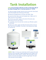
Apex Digital AF-5002 User manual

Category
Sanitary ware
Type
User manual

This manual is also suitable for

ANCHOR
Water
F
ilter
s
pure water in every drop
MODEL
RO
5, RO 5 WITH PUMP AND RO 6
INSTRUCTIONS
MANUAL
Treat your body to pure
goodness
with Anchor
filtered water
A Water supply adapter valve H Prefilter sump
B Cold water shut-off valve J Pre-carbon filter sumps
C Hot water shut-off valve K User friendly wrench
D Auxiliary faucet with handle in closed position L Membrane assembly
E Garbage disposal M Auto shut-off valve
F Drain Saddle N Post-filter
G Storage tank with valve in open position
TAPPING INTO THE COLD WATER LINE
(Using the water supply adapter model SV-1)
NOTE: The drinking water system must be connected to the COLD
water supply only.
1) Turn off the cold water supply to the sink faucet by locating the
round or oblong handle on the right side of the sink cabinet and
turning clockwise until the water supply is off.
NOTE: If the cold water shut-off valve fails to turn off the
water, the house water supply can be turned off at the main
water supply.
2) The water supply adapter can be installed at the faucet
connection (A of Fig.#1) of the cold water line or at the shut-off
valve connection (B of Fig.#1).
torage tank with valve in open position
1) Disconnect the threaded nut at the connection and
thread the water supply adapter, with the flat washer in
place, onto the connection and tighten. Connect the
green tubing to the water supply adapter with the treaded
nut and tighten.
2) Thread the needle valve into the adapter tightly and
turn the handle clockwise all the way in. Turn on cold
water supply to the sink faucet and check for leaks.
TAPPING INTO THE COLD WATER LINE
4) For Stainless Steel Sink: Before using a ½” carbide drill
bit, an indent should be made with a center punch to keep
the drill bit from moving. A small pilot hole will also aid the
½” drill bit.
5) For best results, keep steady firm pressure during the
start of the hole will cause excess wear on the bit and
progress will be slow.
6) Once the hole is complete, clean the area of metal chips
and roughness around the hole. Metal chips will stain
Porcelain.
(Using self-piercing saddle valve model SV-6)
NOTE: This valve is designed for standard copper lines. If
your cold water line is not plumbed with copper line a
special adapter must be used.
1)Turn off cold water supply under the sink and install
the saddle valve to the cold line. Turn the value so that it
pierces the copper cold water line.
2)Install the ¼” White tubing from the first stage filter to
the saddle valve (Fig. #3).
NOTE: Use brass insert and plastic ferrule when
connecting tubing to saddle valve.
NOTE: Depending on the country or place, Different
plumbing pipes require different types of Saddle
Valves.
DRILLING THE HOLE FOR THE FAUCET
NOTE: Safety glasses should be worn to protect your
eyes while drilling the faucet hole.
1)For best results, a ½” carbide-tipped drill bit should be
used to drill a hole into your sink for the auxiliary faucet.
2) Carefully select the faucet location making sure it will
have a neat water fall pattern and that the faucet stud will
be accessible from below once the hole is completed.
3) For Porcelain Sink: Before starting the drill motor,
apply firm downward pressure on the bit until a
crunching occurs. This will help keep the drill bit from
moving when
MOUNTING THE FAUCET
Your unit comes complete with a long reach faucet.
NOTE: Air gap option installation instructions are
available upon request. The following instructions is
for non-air gap option.
1) Slide chrome cover plate and rubber gasket onto stem
of faucet and place faucet onto sink with the stem going
through the hole.
2) Place metal washer and lock washer over threaded
stem of faucet and tighten nut from under the counter
surface to lock the faucet into place. DO NOT OVER
TIGHTEN.
3) Connect the blue tube to the faucet stem under the
counter and tighten. NOTE: Use a brass insert and plastic
ferrule when connecting the blue tube to the faucet
(Fig.4).
DRAIN CLAMP INSTALLATION
1) The drain clamp assembly should be installed above
the trap and on the vertical or horizontal tailpiece (Fig. #5)
2) Mark the hole position on the pipe and drill a ¼” hole
through one side of the pipe (Fig. #6).
3) Make sure to align drain saddle to drilled hole. Attach
drain clamp to drain pipe and tighten the two screws
evenly (Fig #7). NOTE: The center hole on the sponge
must be removed.
4) Connect the Black tubing to the drain
clamp.
POSITIONING THE SYSTEM
1) The head assembly will stand up in the sink cabinet or
can be hung on screws provided.
2) The storage tan k may be laid on its side.
3)The head assembly and/or storage tank maybe placed
up to 15 feet from the point of use with nominal pressure
loss.
CONNECTING THE SYSTEM
1) Compression fittings may be found on the water supply
adapter and the faucet. To make the connections, slide a
compression nut onto the tubing (Fig. #8), slip a white
plastic sleeve onto the tubing with the beveled end
towards the end of the tubing, insert a brass insert into the
tubing, bottom the tubing into the fitting, slide the nut up
and tighten with a wrench. DO NOT OVER TIGHTEN.
NOTE: Do not use brass sleeves on plastic tubing,
use only plastic sleeves on plastic tubing.
1) The plastic fitting on the drain clamp is connected by
slipping the plastic nut onto the tubing, insert brass or
plastic insert into the tubing, bottom the tubing into the
fitting and tighten finger tight.
2) Use the color coded tubing to make the following
connections:
A) The white tubing connects the water supply
adapter to the first clear housing of the head
assembly.
B) The blue tubing connects the faucet to the
outlet side of the post carbon.
C) The yellow tubing connects the storage tank
to the inlet side of the post carbon.
D) The black tubing connects the drain clamp to the
R/O membrane.
START-UP PROCEDURE
2) GAC and Carbon Block:Designed to remove chlorine
form the water supply, as well as organic and inorganic
substance before entering the TFC membrane (average
1) Check to see all connections are made.
2) Check that the pre-filter and pre-carbon sumps are
secure using the housing wrench provided.
3) Slowly turn on the water by turning the needle valve
counterclockwise.
4) The valve handle on top of the tank should be in the
open position, parallel to the valve body.
5) The handle of the faucet should be perpendicular to the
spigot (closed).
6) Check for leaks.
7) The RO-5/50 drinking water system makes 2 gallons of
drinking water per hour and requires 1 to 2 hours before
water is readily available.
8) During this initial fill period, you will hear water being
discharged through the black drain line. This is normal as
the contaminated water is being rejected by the reverse
osmosis membrane.
DO NOT DRINK THE WATER FROM THE
FIRST TANK PRODUCED BY THE SYSTEM.
DISCHARGE THE WATER FROM THE
STORAGE TANK BY OPENING THE
FAUCET. DISCHARGING MIGHT TAKE UP
TO 15 MINUTES.
If you have any difficulties with the installation, or
require additional information on your unit, please
consult with our factory technicians.
We thank you for purchasing our RO-5/50P
Reverse Osmosis unit. Your high quality
processed drinking water. In order to maintain
this high quality water, it is important that
scheduled maintenance be followed.
RECOMMENDED MAINTENANCE
1) Sediment Pre-filter: The pre-filter protects the
system and should be maintained regularly, a clear
housing has been provided for your convenience.
The show-white pre-Filter should be changed when
the outside discolors to a cardboard brown color and
before the inner surface discolors. The life of the pre-
filter will depend upon the condition of your water
supply and should be checked at 3-month intervals
until a filter life is established (average life 6 months).
life 12 months).
3)Post-Carbon: The post-filter should be changed when
you experience an unusual taste and/or odor to the water
and has a nominal life of 1 year.
4)Membrane: The high quality Thin Film Composite
membrane should last between 2 to 4 years depending on
the quality of your local water.
5) Drain your storage tank twice each month to extend the
membrane and have the freshest water in the storage
tank. Drain the storage tank by lifting the faucet handle
into the parallel position with the spigot until water flow
stops from the tank. Return the faucet handle to the closed
position and the tank will refill in 2 hours. It is best to drain
the system before retiring for the evening.
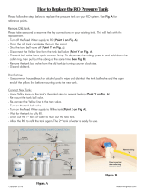
CHANGING THE SEDIMENT, GAC, AND CARBON
BLOCK PRE-CARBON BLOCK PRE-FILTERS
CAUTION: ANY REPLACEMENT FILTERS
OR MEMBRANE NOT RECOMMENDED BY
THE FACTORY CAN CAUSE SEVERE
DAMAGE TO THE SYSTEM AND VOIDS ALL
WARRANTIES.
1) Shut off the feed water to the system by turning the
saddle valve on the water supply adapter clockwise until it
stops.
2) Close the storage tank ball valve by turning the handle
perpendicular to the valve body.
3) Press down on faucet handle to relive pressure.
4) Allow 3-5 minutes for pressure in the system to drop.
5) Remove the filter sumps with the housing wrench by
turning the sump to the left (counterclockwise). If the O-
ring in the sump is stretched or worn, it should be replaced
to maintain a proper seal.
6) Remove the old filter and gaskets (if any) and insert the
new filter.
8) Replace the sump onto the cap by turning it to the right
(clockwise) until the O-ring makes firm contact, like an oil
filter on a car. DO NOT OVER-TIGHTEN.
8) Turn on the feed water to the system by turning the
saddle valve at the water supply adapter counter-
clockwise.
9) Turn the storage tank ball valve handle parallel to the
valve body.
CHANGING THE MEMBRANE
Replacement TFC membranes come with complete changing instructions when ordered.
TROUBLESHOOTING
LEAKS
1) Filter sump: The O-ring in the sump may not be making firm contact, have dirt or hair on it or be stretched. Clean or
replace O-ring and tighten sump to make firm contact with cap.
2) Fitting Connection: Compression - Check that the fitting is tightened with all parts in proper place (refer to Fig. #8).
NO WATER OR SLOW FLOW
1) The system requires 2 hours from start-up to be fully charged and will take longer if it is hooked up to a refrigerator ice
maker.
2) The storage tank can hold up to 2.5 gallons and with heavy use can be depleted to zero. If this occurs, the system will
be fully charged in 2 hours and it becomes a recurring event an additional tank may be added, or a higher production
membrane may be needed.
3) Check colored tubing for correct connections.
4) Check the saddle valve at the water supply adapter is turned all the way counterclockwise for feed water and that
there is no restrictions along the white tubing.
5) Check for restrictions along the blue and yellow tubing and the storage tank ball valve handle should be parallel
(open) to the valve body.
6) Check the pre-filter, if it has a heavy dirt load it can restrict water flow to the system. Change sediment pre-filter
regularly.
7) If the storage tank is heavy with water and will not empty it has lost its air charge and needs to be serviced or
replaced. The air charge in the tank should be 5-7 psi with the tank empty of all water.
CUSTOMER SATISFACTION IS OF PRIMARY CONCERN, PLEASE CALL IN THE EVENT THERE
IS A SERVICE PROBLEM.
Notice: Your RO-5/50 system has been thoroughly tested and inspected for production, rejection, leaks and shut-off
functions at our factory. Therefore, it might have some water in it.
Warning: Do not use this system if feed water has biological contamination or of unknown source. For operating
parameters, please contact our technical support department.
  • Page 1 1
  • Page 2 2
  • Page 3 3
  • Page 4 4
  • Page 5 5
  • Page 6 6

Apex Digital AF-5002 User manual

Category
Sanitary ware
Type
User manual
This manual is also suitable for

Ask a question and I''ll find the answer in the document

Finding information in a document is now easier with AI