
HT-1800DP 4-244-184-11(2) US
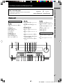
Home Theater
System
4-244-184-11(2)
HT-1800DP
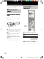
Owner’s Record
The model and serial numbers are located at the rear of the unit. Record the serial
number in the space provided below. Refer to them whenever you call upon your Sony
dealer regarding this product.
Model No. Serial No.
© 2003 Sony Corporation
Operating Instructions
01US01COVU.p65 19/2/03, 9:04 AM1

2
US
HT-1800DP 4-244-184-11(1) US
– Reorient or relocate the receiving antenna.
– Increase the separation between the equipment and
receiver.
– Connect the equipment into an outlet on a circuit
different from that to which the receiver is
connected.
– Consult the dealer or an experienced radio/TV
technician for help.
CAUTION
You are cautioned that any changes or modification
not expressly approved in this manual could void
your authority to operate this equipment.
Note to CATV system installer:
This reminder is provided to call CATV system
installer’s attention to Article 820-40 of the NEC that
provides guidelines for proper grounding and, in
particular, specifies that the cable ground shall be
connected to the grounding system of the building, as
close to the point of cable entry as practical.
For customers in Canada
CAUTION
TO PREVENT ELECTRIC SHOCK, DO NOT USE
THIS POLARIZED AC PLUG WITH AN
EXTENSION CORD, RECEPTACLE OR OTHER
OUTLET UNLESS THE BLADES CAN BE FULLY
INSERTED TO PREVENT BLADE EXPOSURE.
ENERGY STAR
®
is a U.S. registered
mark.
As an
E
NERGY
S
TAR
®
partner, Sony
Corporation has determined that this
product meets the
E
NERGY
S
TAR
®
guidelines for energy efficiency.
This receiver incorporates Dolby* Digital and Pro
Logic Surround and the DTS** Digital Surround
System.
* Manufactured under license from Dolby
Laboratories.
“Dolby”, “Pro Logic” and the double-D symbol are
trademarks of Dolby Laboratories.
** “DTS” and “DTS Digital Surround” are registered
trademarks of Digital Theater Systems, Inc.
WARNING
To prevent fire or shock hazard, do not
expose the unit to rain or moisture.
To prevent fire, do not cover the ventilation of the
apparatus with newspapers, table-cloths, curtains, etc.
And don’t place lighted candles on the apparatus.
To prevent fire or shock hazard, do not place objects
filled with liquids, such as vases, on the apparatus.
Don’t throw away the battery with
general house waste, dispose of it
correctly as chemical waste.
Do not install the appliance in a confined space, such
as a bookcase or built-in cabinet.
For customers in the United States
This symbol is intended to alert the
user to the presence of uninsulated
“dangerous voltage” within the
product’s enclosure that may be of
sufficient magnitude to constitute a
risk of electric shock to persons.
This symbol is intended to alert the
user to the presence of important
operating and maintenance (servicing)
instructions in the literature
accompanying the appliance.
WARNING
This equipment has been tested and found to comply
with the limits for a Class B digital device, pursuant
to Part 15 of the FCC Rules. These limits are
designed to provide reasonable protection against
harmful interference in a residential installation. This
equipment generates, uses, and can radiate radio
frequency energy and, if not installed and used in
accordance with the instructions, may cause harmful
interference to radio communications. However, there
is no guarantee that interference will not occur in a
particular installation. If this equipment does cause
harmful interference to radio or television reception,
which can be determined by turning the equipment
off and on, the user is encouraged to try to correct the
interference by one or more of the following
measures:

3
US
HT-1800DP 4-244-184-11(2) US
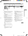
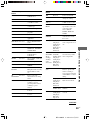
Table of Contents
Other Operations
Naming preset stations and program
sources ........................................... 31
Recording ............................................ 31
Using the Sleep Timer ......................... 32
Adjustments using the SET UP
menu .............................................. 32
Changing the command mode of
the receiver .................................... 33
Operations Using the Remote
RM-PP412
Before you use your remote ................ 34
Remote button description ................... 34
Selecting the command mode
of the remote ................................. 37
Programming the remote ..................... 38
Additional Information
Precautions .......................................... 41
Troubleshooting ................................... 41
Specifications ...................................... 44
Tables of settings using the
MAIN MENU button .................... 47
Adjustable parameters for each
sound field ........................ Back page
List of Button Locations and
Reference Pages
Main unit ............................................... 5
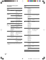
Hooking Up the Components
Required cords ....................................... 6
Antenna hookups ................................... 7
Audio component hookups .................... 8
Video component hookups .................... 9
Digital component hookups ................. 10
Other hookups ..................................... 11
Hooking Up and Setting Up
the Speaker System
Speaker system hookups ..................... 12
Performing initial setup operations ..... 14
Multi channel surround setup .............. 14
Checking the connections .................... 19
Basic Operations
Selecting the component ..................... 20
Changing the display ........................... 21
Enjoying Surround Sound
Using only the front speakers
(2 Channel Stereo) ........................ 22
Enjoying higher fidelity sound ............ 22
Selecting a sound field ........................ 23
Understanding the multi channel
surround displays .......................... 25
Customizing sound fields .................... 26
Receiving Broadcasts
Direct tuning ........................................ 28
Automatic tuning ................................. 29
Preset tuning ........................................ 29

4
US
HT-1800DP 4-244-184-11(2) US
A
KERS
IMPEDANCE USE 8 – 16Ω
CENTER SURROUND
R
R
L
L
4-XXX-XXX-XX AA
Area code
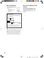
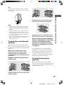
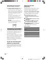
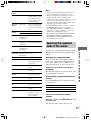
About This Manual
The HT-1800DP consists of:
– Receiver STR-K751P
– Speaker system
• Front/surround speakers SS-MSP75
• Center speaker SS-CNP75
• Sub woofer SA-WMSP85
– DVD player DVP-NS725P
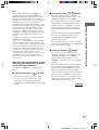
About area codes
The area code of the receiver you purchased is
shown on the lower portion of the rear panel (see
the illustration below).
Any differences in operation, according to the
area code, are clearly indicated in the text, for
example, “Models of area code AA only”.
Tip
The instructions in this manual describe the controls
on the receiver. You can also use the controls on the
supplied remote if they have the same or similar
names as those on the receiver. For details on the use
of your remote, see pages 34 – 40. For details on the
use of your DVD player, refer to the separate
operating instructions supplied with the DVD player.
Note for the supplied remote
RM-PP412
The VIDEO3, TV/SAT, PHONO, AUX,
MULTI CH, SOURCE, DIRECT, AAC
BI-LING, SB DECODING, 12 and ON
SCREEN buttons on the remote are not
available.

List of Button Locations and Reference Pages
5
US
HT-1800DP 4-244-184-11(2) US
g
?/1
qdqfqgqhqjqkqlw;wawd wswfwh wgwj
1784 0 qa qs523
6
9
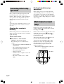
List of Button Locations and Reference Pages
Main unit
How to use this page
Use this page to find the location of buttons that
are mentioned in the text.
M – O
MAIN MENU qf (15, 26, 27, 31,
32, 47)
MASTER VOLUME qs (18, 20,
41)
MD/TAPE 8 (20)
MEMORY wh (29)
MENU +/– qh (15, 26, 27, 31, 32
47)
MENU </> qj (15, 26, 27, 31, 32,
47)
MOVIE (button/indicator) ql (23,
42)
MULTI CHANNEL DECODING
(indicator) ws (20)
MUSIC (button/indicator) qk (23,
24, 42)
P – Z
PHONES (jack) wj (20, 25, 42)
PRESET TUNING +/– wd (29, 30,
45)
TUNER FM/AM q; (20, 29, 30,
31)
TUNING +/– wf (28, 29)
VIDEO 1 5 (20)
VIDEO 2 6 (20)
NUMBERS AND SYMBOLS
2CH (button/indicator) wa (22, 24,
27)
`/1 (power) 1 (14, 19, 27, 33,
45)
ALPHABETICAL ORDER
A – L
A.F.D. (button/indicator) w; (22-
24)
CD 9 (20)
DIMMER 3 (21)
DISPLAY 2 (21, 43)
Display qa (21)
DVD 7 (20)
ENTER qg (31, 33)
FM MODE wg (28)
INPUT MODE qd (20)
IR (receptor) 4 (34, 43)
Illustration number
r
DISPLAY 2 (21, 43)
RR
Name of button/part Reference page

6
US
HT-1800DP 4-244-184-11(2) US
Hooking Up the Components
Before you get started
• Turn off the power to all components before making any connections.
• Do not connect the AC power cord until all of the connections are completed.
• Be sure to make connections firmly to avoid hum and noise.
• When connecting an audio/video cord, be sure to match the color-coded pins to the appropriate jacks on
the components: yellow (video) to yellow; white (left, audio) to white; and red (right, audio) to red.
• When you connect optical digital cords, insert the cord plugs straight in until they click into place.
• Do not bend or tie the optical digital cord.
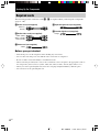
Required cords
The following optional connection cords A – E are required when you hook up the components
(pages 8 – 10).
D Optical digital cord (not supplied)
E Coaxial digital cord (supplied)
Orange
A Audio cord (not supplied)
White (L)
Red (R)
B Audio/video cord (not supplied)
Yellow (video)
White (L/audio)
Red (R/audio)
C Video cord (not supplied)
Yellow

Hooking Up the Components
7
US
HT-1800DP 4-244-184-11(2) US
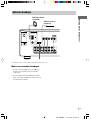
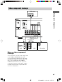
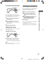
Antenna hookups
FM wire antenna
(supplied)
AM loop antenna
(supplied)
Notes on antenna hookups
• To prevent noise pickup, keep the AM loop
antenna away from the receiver and other
components.
• Be sure to fully extend the FM wire antenna.
• After connecting the FM wire antenna, keep it
as horizontal as possible.
L
R
y
AM
FM
75Ω
COAXIAL
DIGITAL
ANTENNA
MONITOR
SUB
WOOFER
VIDEO 1
VIDEO 2
DVDMD/TAPE
CD
OPTICAL
VIDEO 2
IN
DVD IN
COAXIAL
IN OUT
IN
AUDIO IN AUDIO IN
AUDIO OUT AUDIO IN
VIDEO IN VIDEO IN
VIDEO OUT VIDEO IN
VIDEO OUT
AUDIO
OUT
* The shape of the connector varies depending on the area code.
*

8
US
HT-1800DP 4-244-184-11(2) US
y
AM
FM
75Ω
COAXIAL
DIGITAL
ANTENNA
MONITOR
SUB
WOOFER
VIDEO 1
VIDEO 2
DVDMD/TAPE
CD
OPTICAL
VIDEO 2
IN
DVD IN
COAXIAL
IN OUT
IN
AUDIO IN AUDIO IN
AUDIO OUT AUDIO IN
VIDEO IN VIDEO IN
VIDEO OUT VIDEO IN
VIDEO OUT
AUDIO
OUT
L
R
LINE
L
R
OUTPUT
A
INOUT
LINE
L
R
LINE
INPUT OUTPUT
ç
ç
AA
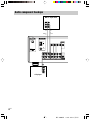
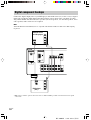
Audio component hookups
MD or Tape deck
CD player

Hooking Up the Components
9
US
HT-1800DP 4-244-184-11(2) US
y
AM
FM
75Ω
COAXIAL
DIGITAL
ANTENNA
MONITOR
SUB
WOOFER
VIDEO 1
VIDEO 2
DVDMD/TAPE
CD
OPTICAL
VIDEO 2
IN
DVD IN
COAXIAL
IN OUT
IN
AUDIO IN AUDIO IN
AUDIO OUT AUDIO IN
VIDEO IN VIDEO IN
VIDEO OUT VIDEO IN
VIDEO OUT
AUDIO
OUT
L
R
VIDEO
IN
INPUT
C
IN
VIDEO
OUT
R
AUDIO
OUT
OUTPUT
L
Ç
B
VIDEO
OUT
R
AUDIO
OUT
VIDEO
IN
AUDIO
IN
OUTPUTINPUT
L
INOUT
Ç
Ç
BB
AUDIO OUT VIDEO
OUT
L
R
OUTPUT
B
Video component hookups
TV monitor
DVD player
Note on video component
hookups
You can connect your TV’s audio output jacks
to the VIDEO 2 AUDIO IN jacks on the
receiver and apply sound effects to the audio
from the TV. In this case, do not connect the
TV’s video output jack to the VIDEO 2
VIDEO IN jack on the receiver. If you are
connecting a separate satellite tuner, connect
both the audio and video output jacks to the
receiver as shown above.
Satellite
tuner or
VCR
VCR

10
US
HT-1800DP 4-244-184-11(2) US
y
AM
FM
75Ω
COAXIAL
DIGITAL
ANTENNA
MONITOR
SUB
WOOFER
VIDEO 1
VIDEO 2
DVDMD/TAPE
CD
OPTICAL
VIDEO 2
IN
DVD IN
COAXIAL
IN OUT
IN
AUDIO IN AUDIO IN
AUDIO OUT AUDIO IN
VIDEO IN VIDEO IN VIDEO OUT VIDEO IN
VIDEO OUT
AUDIO
OUT
L
R
VIDEO
OUT
R
AUDIO
OUT
OUTPUT
L
DIGITAL
OPTICAL
OUTPUT
BD
DIGITAL
COAXIAL
OUTPUT
VIDEO
OUT
R
AUDIO
OUT
OUTPUT
L
E
B
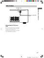
Digital component hookups
DVD player
(etc.)*
Connect the digital output jacks of your DVD player and satellite tuner (etc.) to the receiver’s digital
input jacks to bring the multi channel surround sound of a movie theater into your home. To fully
enjoy multi channel surround sound, five speakers (two front speakers, two surround speakers, and a
center speaker) and a sub woofer are required.
Note
All the OPTICAL and COAXIAL jacks are compatible with 96 kHz, 48 kHz, 44.1 kHz and 32 kHz sampling
frequencies.
Satellite tuner
or DVD player*
* Make either coaxial or optical connections. We recommend making coaxial connections instead of optical
connections.

Hooking Up the Components
11
US
HT-1800DP 4-244-184-11(2) US
Connecting the AC power
cord
Before connecting the AC power cord of this
receiver to a wall outlet, connect the speaker
system to the receiver (page 12).
Connect the AC power cord(s) of your audio/
video components to a wall outlet.
Other hookups
SPEAKERS
IMPEDANCE USE 8 – 16Ω
FRONT CENTER SURROUND
R
R
L
L
R
R
L
L
b
AC power cord
To a wall outlet

12
US
HT-1800DP 4-244-184-11(2) US
SPEAKERS
IMPEDANCE USE 8 – 16Ω
MONITOR
SUB
WOOFER
VIDEO OUT
AUDIO
OUT
FRONT CENTER SURROUND
R
R
L
L
R
R
L
L
E
e
Ee
A
A
INPUT
AUDIO
IN
B
E
e
A
E
e
A
E
e
A
b
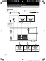
Hooking Up and Setting Up the Speaker System
Front speaker (L)Front speaker (R)
Center speaker Surround speaker
(L)
Surround speaker
(R)
Active sub woofer
B Monaural audio cord (supplied)
Black
To a wall outlet
(Switch the power
(POWER) to off
before connecting
the power cord.)
Speaker system hookups
Required cords
A Speaker cords (supplied)
(+)
(–)

Hooking Up and Setting Up the Speaker System
13
US
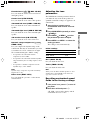
HT-1800DP 4-244-184-11(2) US
Stripped cords are touching each other
due to excessive removal of insulation.
Stripped cords are not fully attached and
are touching the rear panel of the receiver.
After connecting all the components,
speakers, and AC power cord, output
a test tone to check that all the
speakers are connected correctly.
For details on outputting a test tone,
see page 18.
If no sound is heard from a speaker while
outputting a test tone or a test tone is output
from a speaker other than the one whose name
is currently displayed on the receiver, the
speaker may be short-circuited. If this happens,
check the speaker connection again.
To avoid damaging your
speakers
Make sure that you turn down the volume
before you turn off the receiver. When you turn
on the receiver, the volume remains at the level
you turn off the receiver.
Tip
To prevent speaker vibration or movement while
listening, attach the supplied foot pads at the bottom
of the speakers.
Notes
• Connect the long speaker connecting cords to the
surround speaker terminals and the short speaker
connecting cords to the front and center speaker
terminals.
• Twist the stripped ends of the speaker cords about
2/3 inch. Be sure to match the speaker cord to the
appropriate terminal on the components: + to + and
– to –. If the cords are reversed, the sound will be
distorted and will lack bass.
• If you use speakers with low maximum input rating,
adjust the volume carefully to avoid excessive
output on the speakers.
To avoid short-circuiting the
speakers
Short-circuiting of the speakers may damage
the receiver. To prevent this, make sure to take
the following precautions when connecting the
speakers.
Make sure the stripped ends of each
speaker cord does not touch another
speaker terminal, the stripped end of
another speaker cord, or the metal parts of
the receiver.
Examples of poor conditions of the
speaker cord
Stripped speaker cord is touching another
speaker terminal.

14
US
HT-1800DP 4-244-184-11(2) US
45°
90°
20°
B
CC
AA
Performing initial setup
operations
Once you have hooked up the speakers and
turned on the power, clear the receiver’s
memory. Then specify the speaker parameters
(size, position, etc.) and perform any other
initial setup operations necessary for your
system.
Tip
To check the audio output during settings (to set up
while outputting the sound), check the connection
(page 19).
Clearing the receiver’s
memory
Before using your receiver for the first time, or
when you want to clear the receiver’s memory,
do the following.
1 Turn off the receiver.
2 Hold down ?/1 for 5 seconds.
“INITIAL” appears in the display.
The following are reset to their factory
settings.
• All settings in the SET UP, LEVEL and
TONE menus.
• The sound field memorized for each
input selector and preset station.
• All sound field parameters.
• All preset stations.
• All index names of input selectors and
preset stations.
• The master volume is set to “VOL
MIN”.
Performing initial setup
operations
Before using your receiver for the first time,
adjust SET UP parameters so that the receiver
correspond to your system. For the adjustable
parameters, see the table on page 47. See pages
14–18 for speaker settings and pages 32–33 for
other settings.
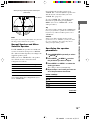
Multi channel surround
setup
For the best possible surround sound, all
speakers should be the same distance from the
listening position (A).
However, the receiver lets you place the center
speaker up to 5 feet closer (B) and the
surround speakers up to 15 feet closer (C) to
the listening position.
The front speakers can be placed from 3 to 23
feet from the listening position (A).
You can place the surround speakers either
behind you or to the side, depending on the
shape of your room (etc.). However, we
recommend that you place the surround
speakers behind you.
When placing surround speakers to your side
(long room)
Sub woofer

Hooking Up and Setting Up the Speaker System
15
US
HT-1800DP 4-244-184-11(2) US
45°
90°
20°
B
CC
A
A
continued
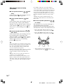
When placing surround speakers behind you
(wide room)
Note
Do not place the center speaker further away from the
listening position than the front speakers.
Normal Speaker and Micro
Satellite Speaker
For HT-1800DP, the speaker size and the sub
woofer selection has been preset to “MICRO
SP.” (Micro Satellite Speaker) according to the
supplied speaker system.
When you select “MICRO SP.”, the speaker
size and sub woofer selection has been
configurated as follows:
Speaker Settings
FRONT SMALL
CENTER SMALL
SURROUND SMALL
SUB WOOFER YES
You cannot change the configuration if you
select “MICRO SP.”.
If you change the speaker system, select
“NORM. SP.”. You can adjust the speaker size
and sub woofer selection when you select
“NORM. SP.” (page 17).
To select “NORM. SP.”, turn off the power,
then turn on again while pressing MAIN
MENU. (To reset to “MICRO SP.”, do the
same procedure.)
Tip
The setting for Micro Satellite Speaker (MICRO SP.)
has been programmed to optimize the sound balance.
If you use Sony’s Micro Satellite Speakers, select
“MICRO SP.”.
Caution
When you use Micro Satellite Speakers and the
speaker size is set to “LARGE”, you may not obtain
the correct soundstage. The speaker may also be
damaged at high volume position.
Specifying the speaker
parameters
1 Press MAIN MENU repeatedly to select
“ SET UP ”.
2 Press MENU or MENU to select
the parameter you want to adjust.
3 Press MENU + or MENU – to select the
setting you want.
The setting is entered automatically.
4 Repeat steps 2 and 3 until you have set
all of the parameters that follow.
Initial settings
Parameter Initial setting
L
R
DIST. XX ft. 10 ft.
C
DIST. XX ft. 10 ft.
SL
SR
DIST. XX ft. 10 ft.
SL
SR
PL. XXXX LOW
Sub woofer

16
US
HT-1800DP 4-244-184-11(2) US
60
30
A
B
A
B
Multi channel surround setup
(continued)
x Front speaker distance (
L
R
DIST.
XX ft.)
Set the distance from your listening position to
the front speakers (A on page 14).
x Center speaker distance (
C
DIST.
XX ft.)
Set the distance from your listening position to
the center speaker. Center speaker distance
should be set from a distance equal to the front
speaker distance (A on page 14) to a distance
5 feet closer to your listening position (B on
page 14).
x Surround speaker distance (
SL
SR
DIST. XX ft.)
Set the distance from your listening position to
the surround speakers. Surround speaker
distance should be set from a distance equal to
the front speaker distance (A on page 14) to a
distance 15 feet closer to your listening
position (C on page 14).
Tip
The receiver allows you to input the speaker position
in terms of distance. However, it is not possible to set
the center speaker further than the front speakers.
Also, the center speaker cannot be set more than
5 feet closer than the front speakers.
Likewise, the surround speakers can not be set further
away from the listening position than the front
speakers. And they can be no more than 15 feet
closer.
This is because incorrect speaker placement is not
conducive to enjoy surround sound.
Please note that, setting the speaker distance closer
than the actual location of the speakers will cause a
delay in the output of the sound from that speaker. In
other words, the speaker will sound like it is further
away.
For example, setting the center speaker distance
3~6 feet closer than the actual speaker position will
create a fairly realistic sensation of being “inside” the
screen. If you cannot obtain a satisfactory surround
effect because the surround speakers are too close,
setting the surround speaker distance closer (shorter)
than the actual distance will create a larger sound
stage.
Adjusting these parameter while listening to the
sound often results in much better surround sound.
Give it a try!
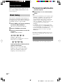
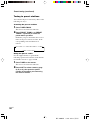
x Surround speaker placement (
SL
SR
PL. XXXX)*
This parameter lets you specify the height of
your surround speakers for proper
implementation of the Digital Cinema Sound
surround modes. Refer to the illustration below.
• Select “PL. LOW” if the location of your
surround speakers corresponds to section A.
• Select “PL. HIGH” if the location of your
surround speakers corresponds to section B.
* These parameters are not available when
“Surround speaker size (
SL
SR
)” is set to “NO”.

Hooking Up and Setting Up the Speaker System
17
US
HT-1800DP 4-244-184-11(2) US
continued
Tip
The surround speaker placement parameter is
designed specifically for implementation of the
Digital Cinema Sound modes with virtual elements.
With the Digital Cinema Sound modes, speaker
placement is not as critical as other modes. All modes
with virtual elements were designed under the
premise that the surround speaker would be located
behind the listening position, but presentation remains
fairly consistent even with the surround speakers
positioned at a rather wide angle. However, if the
speakers are pointing towards the listener from the
immediate left and right of the listening position, the
sound fields with virtual elements will not be as
effective.
Nevertheless, each listening environment has many
variables, like wall reflections.
Therefore, we recommend that you playback multi
channel surround encoded software and listen to the
effect each setting has on your listening environment.
Choose the setting that provides a good sense of
spaciousness and that best succeeds in forming a
cohesive space between the surround sound from the
surround speakers and the sound of the front
speakers. If you are not sure which sounds best, select
“PL. LOW” and then use the speaker distance
parameter and speaker level adjustments to obtain
proper balance.
Only when you use the speaker system
other than the supplied one, be sure to
set the following parameters.
For details on “NORM. SP.” (Normal Speaker), see
page 15.
x Sub woofer selection (
SW
S.W. XXX)
• If you connect a sub woofer, select “YES”.
• If you do not connect a sub woofer, select
“NO”. This activates the bass redirection
circuitry and outputs the LFE signals from other
speakers.
x Front speaker size (
L
R
XXXXX)
• If you connect large speakers that will
effectively reproduce bass frequencies, select
“LARGE”. Normally, select “LARGE”.
• If the sound is distorted, or you feel a lack of
surround effects when using multi channel
surround sound, select “SMALL” to activate
the bass redirection circuitry and output the
front channel bass frequencies from the sub
woofer.
• When the front speakers are set to “SMALL”,
the center and surround speakers are also
automatically set to “SMALL” (unless
previously set to “NO”).
• When the sub woofer is set to “NO”, the front
speakers are automatically set to “LARGE” and
you cannot change this setting.
x Center speaker size (
C
XXXXX)
• If you connect a large speaker that will
effectively reproduce bass frequencies, select
“LARGE”. Normally, select “LARGE”.
However, if the front speakers are set to
“SMALL”, you cannot set the center speaker to
“LARGE”.
• If the sound is distorted, or you feel a lack of
surround effects when using multi channel
surround sound, select “SMALL” to activate
the bass redirection circuitry and output the
center channel bass frequencies from the front
speakers (if set to “LARGE”) or sub woofer.*
1
• If you do not connect a center speaker, select
“NO”. The sound of the center channel will be
output from the front speakers.*
2

18
US
HT-1800DP 4-244-184-11(2) US
Multi channel surround setup
(continued)
x Surround speaker size (
SL
SR
XXXXX)
• If you connect large speakers that will
effectively reproduce bass frequencies, select
“LARGE”. Normally, select “LARGE”.
However, if the front speakers are set to
“SMALL”, you cannot set the surround
speakers to “LARGE”.
• If the sound is distorted, or you feel a lack of
surround effects when using multi channel
surround sound, select “SMALL” to activate
the bass redirection circuitry and output the
surround channel bass frequencies from the sub
woofer or other “LARGE” speakers.
• If you do not connect surround speakers, select
“NO”.*
3
Tip
*1–*3 correspond to the following Dolby Pro Logic
modes
*1 NORMAL
*2 PHANTOM
*3 3 STEREO
Tip
Internally, the LARGE and SMALL settings for each
speaker determine whether the internal sound
processor will cut the bass signal from that channel.
When the bass is cut from a channel, the bass
redirection circuitry sends the corresponding bass
frequencies to the sub woofer or other “LARGE”
speakers.
However, since bass sounds have a certain amount of
directionality, it is best not to cut them, if possible.
Therefore, even when using small speakers, you can
set them to “LARGE” if you want to output the bass
frequencies from that speaker. On the other hand, if
you are using a large speaker, but prefer not to have
bass frequencies output from that speaker, set it to
“SMALL”.
If the overall sound level is lower than you prefer, set
all speakers to “LARGE”. If there is not enough bass,
you can use the BASS parameter in the TONE menu
to boost the bass levels. To adjust the bass, see page
27.
Adjusting the speaker level
Use the remote while seated in your listening
position to adjust the level of each speaker.
Note
The receiver incorporates a new test tone with a
frequency centered at 800 Hz for easier speaker level
adjustment.
1 Press ?/1 on the remote to turn on the
receiver.
2 Press TEST TONE on the remote.
“T. TONE” appears in the display and you
will hear the test tone from each speaker in
sequence.
Front (left) t Center t Front (right) t
Surround (right) t Surround (left) t
Sub woofer
3 Adjust the speaker level and balance
using the LEVEL menu so that the level
of the test tone sounds the same from
each speaker.
For details on the LEVEL menu, see page
26.
While adjusting, the test tone is output from
the speaker whose adjustment is performed.
4 Press TEST TONE again to turn off the
test tone.
Tip
You can adjust the level of all speakers at the same
time. Press MASTER VOL +/– on the remote or turn
MASTER VOLUME on the receiver.
Notes
• The adjusted value are shown in the display during
adjustment.
• Although these adjustments can also be made via
the front panel using the LEVEL menu (when the
test tone is output, the receiver switches to the
LEVEL menu automatically), we recommend you
follow the procedure described above and adjust the
speaker levels from your listening position using the
remote.

Hooking Up and Setting Up the Speaker System
19
US
HT-1800DP 4-244-184-11(2) US
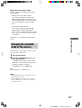
LEVEL
POWER
POWER indicator
Listening to the sub woofer
First, turn down the volume on the receiver.
The volume should be set to minimum before
you begin playing the program source.
1 Turn on the receiver and select the
program source.
2 Press POWER on the sub woofer.
The POWER indicator on the sub woofer
lights up in green.
3 Play the program source.
Adjusting the sound
Slight adjustments to the system can enhance
your sound enjoyment.
Adjusting the sub woofer
1 Rotate LEVEL to adjust the volume.
Set the volume level to best suit your
preference according to the program source.
Note
Do not turn the volume of the woofer to maximum.
Extraneous noise may be heard.
Checking the connections
After connecting all of your components to the
receiver, do the following to verify that the
connections were made correctly.
1 Press ?/1 to turn on the receiver.
2 Turn on the component that you
connected (e.g., CD player or tape
deck).
3 Press the input selector button (e.g.,
CD or MD/TAPE) to select the
component (program source).
4 Start playing.
If you do not obtain normal sound output after
performing this procedure, see
“Troubleshooting” on page 41 and take the
appropriate measures to correct the problem.

20
US
HT-1800DP 4-244-184-11(2) US
Basic Operations
Selecting the component
Input Selector buttons
Press the input selector button to select the
component you want to use.
To select Press
VCR VIDEO 1 or VIDEO 2
Satellite tuner VIDEO 2
DVD player DVD
MD or Tape deck MD/TAPE
CD player CD
Built in tuner TUNER FM/AM
After turning on the component you selected,
select the component and play the program
source.
• After selecting VCR or DVD player, turn on the
TV and set the TV’s video input to match the
component you selected.
INPUT MODE
Press INPUT MODE to select the input mode
for your digital components.
Each time you press the button, the input mode
of the currently selected component switches.
Select To
AUTO IN Give priority to digital
signals when there are both
digital and analog
connections. If there are no
digital signals, analog is
selected.
COAX IN Specify the digital audio
signals input to the
DIGITAL COAXIAL input
jacks.
Select To
OPT IN Specify the digital audio
signals input to the
DIGITAL OPTICAL input
jacks.
ANALOG Specify the analog audio
signals input to the AUDIO
IN (L/R) jacks.
Note
When the 96 kHz digital signal is input, the tone,
sound field and effect level do not function.
MULTI CHANNEL DECODING
indicator
This indicator lights up when the unit is
decoding signals recorded in a multi channel
format.
MUTING
Press MUTING on the remote to mute the
sound. Press again to cancel the muting
function. The muting function is also canceled
when you turn the power on or turn the
MASTER VOLUME to turn the volume up.
PHONES
Use to connect headphones.
• When the headphones are connected, speaker
output is automatically canceled and “SP” do
not light up in the display.
Page is loading ...
Page is loading ...
Page is loading ...
Page is loading ...
Page is loading ...
Page is loading ...
Page is loading ...
Page is loading ...
Page is loading ...
Page is loading ...
Page is loading ...
Page is loading ...
Page is loading ...
Page is loading ...
Page is loading ...
Page is loading ...
Page is loading ...
Page is loading ...
Page is loading ...
Page is loading ...
Page is loading ...
Page is loading ...
Page is loading ...
Page is loading ...
Page is loading ...
Page is loading ...
Page is loading ...
Page is loading ...
-
 1
1
-
 2
2
-
 3
3
-
 4
4
-
 5
5
-
 6
6
-
 7
7
-
 8
8
-
 9
9
-
 10
10
-
 11
11
-
 12
12
-
 13
13
-
 14
14
-
 15
15
-
 16
16
-
 17
17
-
 18
18
-
 19
19
-
 20
20
-
 21
21
-
 22
22
-
 23
23
-
 24
24
-
 25
25
-
 26
26
-
 27
27
-
 28
28
-
 29
29
-
 30
30
-
 31
31
-
 32
32
-
 33
33
-
 34
34
-
 35
35
-
 36
36
-
 37
37
-
 38
38
-
 39
39
-
 40
40
-
 41
41
-
 42
42
-
 43
43
-
 44
44
-
 45
45
-
 46
46
-
 47
47
-
 48
48


Sony HT-1800DP User manual
- Category
- Home cinema systems
- Type
- User manual
Ask a question and I''ll find the answer in the document
Finding information in a document is now easier with AI
Related papers
-
Sony HT-1750DP User manual
-
-
-
-
-
-
Sony STR-DE375 Operating instructions
-
-
-
Other documents
-
Panasonic SUX501 Operating instructions
-
Samsung MAX-DA75 User manual
-
Sharp Stereo System HT-DD5000 User manual
-
Magnavox MRD-200 User manual
-
RCA RV-9978 User manual
-
Kenwood NV-301 User manual
-
 Electrohome RV-3798 User manual
-
Philips MRD250S - 5 Disc Dvd Receiver Dig. Home Cinema User manual
-
 Pyle Pro PT-600A Operating instructions
-
Xantech AM/FM Radio Tuner User manual

