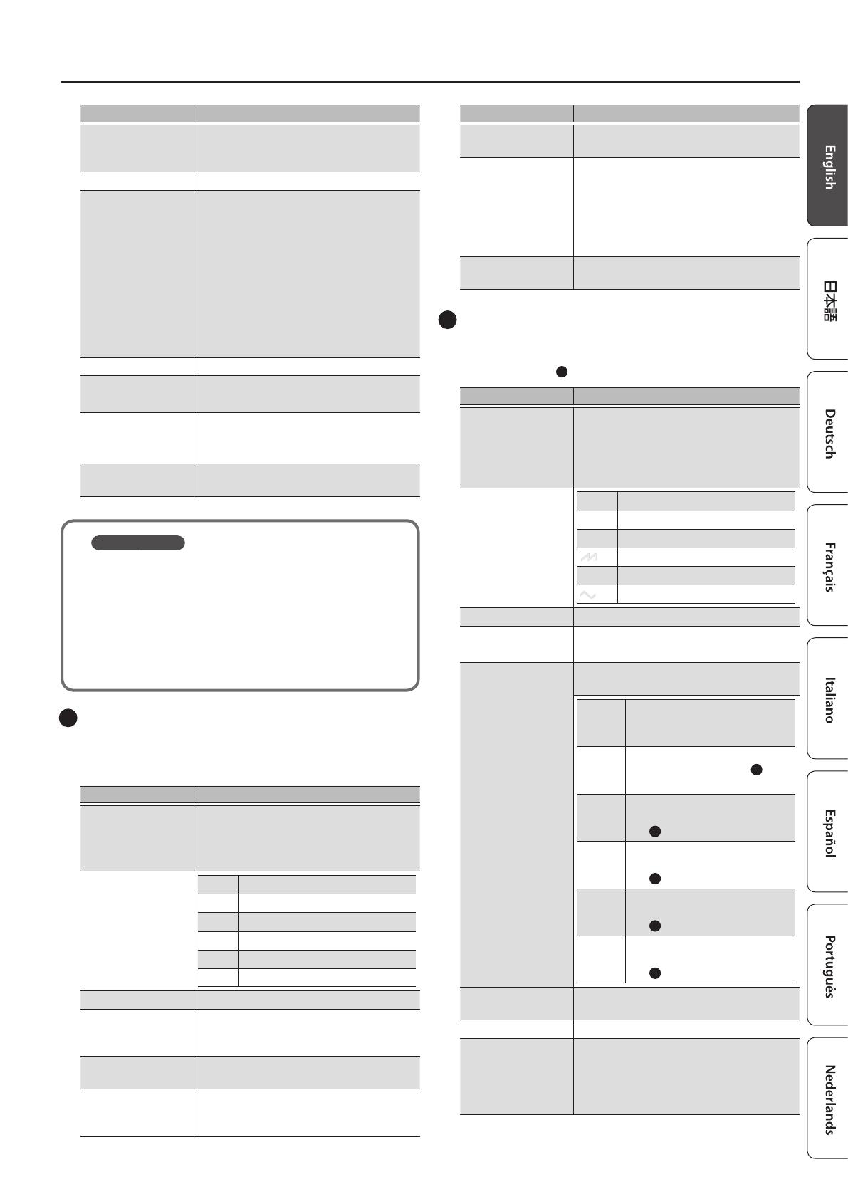
Roland SYSTEM-8 Owner's manual

Category
Sequencer
Type
Owner's manual
Owners Manual (this document)
Read this rst. It explains the basic things you need to know in order
to use the SYSTEM-8.
PDF Manual (download from the Web)
5 Reference Manual
This explains all functions of the SYSTEM-8.
To obtain the PDF manual
1. Enter the following URL in your computer.
http://www.roland.com/manuals/
I
2. Choose “SYSTEM-8” as the product name.
Contents
Panel Descriptions . . . . . . . . . . . . . . . . . . . . . . . . . . . . . . . . . . . . . . . 2
Top Panel . . . . . . . . . . . . . . . . . . . . . . . . . . . . . . . . . . . . . . . . . . . . . 2
Rear Panel . . . . . . . . . . . . . . . . . . . . . . . . . . . . . . . . . . . . . . . . . . . . 6
Placing the SYSTEM-8 on a Stand (KS-18Z) . . . . . . . . . . . . . . 7
Introduction . . . . . . . . . . . . . . . . . . . . . . . . . . . . . . . . . . . . . . . . . . . . . 8
An Overview of the SYSTEM-8 . . . . . . . . . . . . . . . . . . . . . . . . . . 8
Turning On/O the Power . . . . . . . . . . . . . . . . . . . . . . . . . . . . . . 8
Selecting Sounds (Patches/Performances) . . . . . . . . . . . . . . . 9
Editing the Sounds . . . . . . . . . . . . . . . . . . . . . . . . . . . . . . . . . . . . . . 10
Editing a Patch . . . . . . . . . . . . . . . . . . . . . . . . . . . . . . . . . . . . . . . . 10
Editing a Performance . . . . . . . . . . . . . . . . . . . . . . . . . . . . . . . . . 10
Saving a Sound (WRITE) . . . . . . . . . . . . . . . . . . . . . . . . . . . . . . . . 11
Playing Arpeggios or Chords . . . . . . . . . . . . . . . . . . . . . . . . . . . . 13
Playing Arpeggios . . . . . . . . . . . . . . . . . . . . . . . . . . . . . . . . . . . . . 13
Using Chord Memory . . . . . . . . . . . . . . . . . . . . . . . . . . . . . . . . . . 13
Entering a Chord . . . . . . . . . . . . . . . . . . . . . . . . . . . . . . . . . . . . . . 13
Step Sequencer . . . . . . . . . . . . . . . . . . . . . . . . . . . . . . . . . . . . . . . . . . 14
Playing the Step Sequencer . . . . . . . . . . . . . . . . . . . . . . . . . . . . 14
Recording on the Step Sequencer . . . . . . . . . . . . . . . . . . . . . . 15
Saving Step Sequencer Data (PATTERN WRITE) . . . . . . . . . . . 17
Other Functions of the Step Sequencer (MENU) . . . . . . . . . . 17
Connecting External Devices . . . . . . . . . . . . . . . . . . . . . . . . . . . . 18
Using the SYSTEM-8 as a MIDI Controller . . . . . . . . . . . . . . . . 18
Connecting an Analog Synthesizer via the CV/GATE
Output . . . . . . . . . . . . . . . . . . . . . . . . . . . . . . . . . . . . . . . . . . . . . . . 18
Inputting an External Audio Source . . . . . . . . . . . . . . . . . . . . . 18
Connecting a Computer via USB . . . . . . . . . . . . . . . . . . . . . . . . 18
Overall Settings for the SYSTEM-8 . . . . . . . . . . . . . . . . . . . . . . . 19
Accessing the MENU Screens . . . . . . . . . . . . . . . . . . . . . . . . . . . 19
Making System Settings (SYSTEM) . . . . . . . . . . . . . . . . . . . . . . 19
Convenient Functions (UTILITY) . . . . . . . . . . . . . . . . . . . . . . . . 19
Making the Power Automatically Turn O After a Time
(Auto O) . . . . . . . . . . . . . . . . . . . . . . . . . . . . . . . . . . . . . . . . . . . . . 21
Error Messages . . . . . . . . . . . . . . . . . . . . . . . . . . . . . . . . . . . . . . . . . . 22
Main Specications . . . . . . . . . . . . . . . . . . . . . . . . . . . . . . . . . . . . . . 22
USING THE UNIT SAFELY . . . . . . . . . . . . . . . . . . . . . . . . . . . . . . . . . 23
IMPORTANT NOTES . . . . . . . . . . . . . . . . . . . . . . . . . . . . . . . . . . . . . . 24
Before using this unit, carefully read “USING THE UNIT SAFELY and
“IMPORTANT NOTES” (leaet “USING THE UNIT SAFELY” and Owner’s
Manual p. 23–p. 24). After reading, keep the document(s)
including those sections where it will be available for immediate
reference.
Copyright © 2016 ROLAND CORPORATION
Owners Manual
2
Panel Descriptions
Top Panel
1
Common section
Here you can make the following settings for the SYSTEM-8.
Controller Explanation
[VOLUME] knob Adjusts the volume.
[INPUT] knob
Adjusts the volume level of the INPUT R
and L/MONO jacks.
PEAK indicator
Indicates the analog input level of the rear
panel INPUT R, L/MONO jacks.
The PEAK indicator lights if the input level
is excessive.
Adjust the volume of your connected
equipment so that this indicator lights
occasionally.
[VOCODER] button Switches the vocoder on/o.
[ARPEGGIO] button Switches the arpeggiator on/o (p. 13).
[ARP TYPE] knob Selects the arpeggio type.
[ARP STEP] knob
Selects the note value for each step of the
arpeggio.
[KEY HOLD] button Turns the key hold function on/o.
[CHORD MEMORY]
button
Turns the chord memory function on/o
(p. 13).
[VELOCITY OFF]
button
Notes sound at the same volume even if
your playing dynamics vary.
[TRANSPOSE]
button
Turns the transpose function on/o.
OCTAVE [DOWN]
[UP] buttons
Octave shift
These buttons let you shift the pitch range
of the keyboard in one-octave units. The
button is lit if the pitch is shifted by one
octave, and blinking if the pitch is shifted
by two or three octaves.
Key transpose
By pressing a [DOWN] [UP] button while
holding down the [TRANSPOSE] button,
you can transpose (shift the pitch of) the
keyboard in semitone units.
MODE [PATCH]
button
Switches to Patch mode (p. 9, p. 10).
Controller Explanation
MODE
[PERFORMANCE]
button
Switches to Performance mode (p. 9, p. 10).
PART ON/OFF
[LOWER] [UPPER]
buttons
In performance mode, switch the lower
part or upper part on/o.
PANEL SELECT
[LOWER] [UPPER]
button
In performance mode, select the part
(lower or upper) that is the target of panel
operations.
[MANUAL] button
Makes the sound reect the current
settings of the knobs and sliders.
[PORTAMENTO]
knob
Adjusts the time over which pitch change
occurs when portamento is applied.
Portamento is an eect that smoothly
changes the pitch between one key and
the next-played key.
[LEGATO] button
Applies portamento only when you play
legato (i.e., when you press the next key
before releasing the previous key).
[TEMPO] knob
Species the tempo of the step sequencer
and arpeggiator. The indicator blinks at the
specied tempo.
[TEMPO SYNC]
button
The modulation speed (RATE) of the
2
LFO section and the delay time (TIME) of
the
9
EFFECTS section are synchronized
to the tempo.
[MONO] button
If this is on (lit), the synth will play
monophonically (single notes).
If this is blinking, the synth will play all
sounds in unison (UNISON mode).
MODEL [SYSTEM-8]
[PLUG-OUT 1]–
[PLUG-OUT 3]
buttons
When the [SYSTEM-8] button is on, this
instrument operates as the SYSTEM-8
synthesizer. When one of the [PLUG-
OUT 1–3] buttons is on, this instrument
operates as a plug-out synthesizer.
&
About Plug-Out (p. 3)
[WRITE] button
Saves sounds and step sequencer settings
(p. 11, p. 17, p. 19).
1
2 3
4 5 6 7 8 9
11
12
10
3
Panel Descriptions
Controller Explanation
[SHIFT] button
When used in conjunction with other
buttons or knobs, lets you view parameters
or edit dierent parameters.
[MENU] button Accesses the MENU screen (p. 19).
Display
Shows various information for the
operation.
* The explanations in this manual include
illustrations that depict what should
typically be shown by the display. Note,
however, that your unit may incorporate
a newer, enhanced version of the system
(e.g., includes newer sounds), so what
you actually see in the display may
not always match what appears in the
manual.
[VALUE] knob Changes the value at the cursor position.
Cursor [
K
] [
J
]
buttons
Moves the cursor left/right.
Alternatively, switch screens.
[EXIT] button
Returns you to the previous screen.
In some screens, this cancels the operation
currently being executed.
[ENTER] button
Press this to conrm a value or execute an
operation.
About Plug-Out
You can install (plug-out) separately sold plug-out
compatible software synthesizers on the SYSTEM-8 and play
them.
5 For details on dedicated plug-out software synthesizers
and how to obtain them, refer to the Roland website.
&
http://roland.cm/system8
2
LFO
Here you can create cyclic change (modulation) in the sound
by applying vibrato (pitch modulation) or tremolo (volume
modulation).
Controller Explanation (for variation 1)
[VARIATION] knob
Selects the variation of the LFO section.
&
For an explanation of variations 2 and
following, refer to “Reference Manual”
(PDF).
Wave knob
R
Sine wave
S
Triangle wave
T
Sawtooth wave
U
Square wave
W
Sample and Hold
RND Random wave
[PITCH] knob Modulates the pitch of the sound (vibrato).
[FADE TIME] knob
Species the time from when the tone
sounds until the LFO reaches its maximum
amplitude.
[FILTER] knob
Modulates the FILTER CUTOFF (cuto
frequency).
[KEY TRIG] button
Species whether the LFO waveform is
synchronized to start the moment you
press a key (on) or is not synchronized (o).
Controller Explanation (for variation 1)
[TRIG ENV] button
Causes the envelope to start repeatedly at
the LFO cycle (on).
[RATE] knob
Determines the speed of the LFO
modulation.
The indicator blinks at the speed (rate) of
the LFO modulation.
This knob is a GRF (GRIFFER) knob which
allows high-precision adjustments.
[AMP] knob
Allows the LFO to modulate the AMP LEVEL
(volume), producing a tremolo eect.
3
OSC 1, OSC 2
Here you can select the waveform that determines the character of
the sound, and specify its pitch. The SYSTEM-8 has three oscillators
(OSC 1, OSC 2, and
4
OSC 3/SUB OSC).
Controller Explanation (for variation 1)
[VARIATION] knob
Select the variation of the OSC 1 and OSC
2 sections.
&
For an explanation of variations 2 and
following, refer to “Reference Manual”
(PDF).
Wave knob
T
Sawtooth wave
U
Square wave
S
Triangle wave
T
Sawtooth wave2
U
Square wave2
S
Triangle wave2
Octave (feet) knob Species the octave of the oscillator.
[COLOR] knob
Adjusts the tonal character.
The result depends on the waveform.
[MOD] knob
Selects the source that is modulated by the
[COLOR] knob.
MAN
The sound is determined by the
position of the [COLOR] knob. It
will not vary over time.
LFO
The sound varies over time at
the rate specied in the
2
LFO
section.
P. ENV
The sound changes over time
according to the envelope of
the
6
PITCH section.
F. ENV
The sound changes over time
according to the envelope of
the
7
FILTER section.
A. ENV
The sound changes over time
according to the envelope of
the
8
AMP section.
OSC 3
The sound changes over time
according to the frequency of
the
4
OSC 3.
[COARSE TUNE]
knob
Adjusts the pitch in semitone steps.
[FINE TUNE] knob Allows ne pitch adjustments.
[CROSS MOD] knob
(OSC 1 only)
Modies the OSC 1 frequency according
to the OSC 2 waveform. Turning the knob
toward the right makes OSC 1 become
a more complex sound, allowing you to
create metallic sounds or sound eects.
T
U
S
4
Panel Descriptions
Controller Explanation (for variation 1)
[RING] button
(OSC 2 only)
This is a ring modulator. It generates a
complex waveform by multiplying OSC 1
and OSC 2.
OSC 1
OSC 2
[SYNC] button
(OSC 2 only)
This is oscillator sync. It generates a
complex waveform by forcibly resetting
OSC 2 to the beginning of its cycle in
synchronization with the OSC 1 frequency.
OSC 1
OSC 2
4
OSC 3/SUB OSC
Controller Explanation
Wave knob
Selects the waveform that is the basis of
the sound.
R
(Sine wave), -1Oct, -2Oct,
S
(Triangle wave), -1Oct, -2Oct
[COLOR] knob The result depends on the waveform.
[TUNE] knob Adjusts the pitch of the oscillator.
5
MIXER
Here you can adjust the volume of OSC 1, OSC 2, OSC 3/sub-
oscillator, and noise.
Controller Explanation
[OSC 1] knob Adjusts the volume of the OSC 1.
[OSC 2] knob Adjusts the volume of the OSC 2.
[OSC 3/SUB OSC]
knob
Adjusts the volume of the OSC 3/sub-
oscillator.
[NOISE] knob Adjusts the volume of the noise.
[NOISE TYPE]
button
Selects the type of the noise.
Lit: white noise
Unlit: pink noise
6
PITCH
Here you can create time-varying change (envelope) for pitch.
Controller Explanation
[ENV] knob
If this knob is turned toward the right, the
pitch initially becomes higher and then
returns to the pitch of the key you pressed.
If this knob is turned toward the left, the
pitch initially becomes lower and then
returns to the pitch of the key you pressed.
[A] slider
These sliders operate similarly to the [A][D]
sliders of the
8
AMP section (they aect
the pitch rather than the volume).
[D] slider
7
FILTER
These settings determine the brightness and thickness of the
sound. Here you can also specify the time-varying change
(envelope) for the lter.
Controller Explanation (for variation 1)
[VARIATION] knob
Selects the variation of the FILTER section.
&
For an explanation of variations 2 and
following, refer to “Reference Manual”
(PDF).
[CUTOFF] knob
Species the cuto frequency of the lter.
This knob is a GRF (GRIFFER) knob which
allows high-precision adjustments.
Filter type knob
Selects the slope of the lter.
LPF: -24 dB, -18 dB, -12 dB
-18 dB
-12 dB
-24 dB
Level
Frequency
HPF: -12 dB, -18 dB, -24 dB
-18 dB
-12 dB
-24 dB
Level
Frequency
[RESO] knob
Resonance boosts the sound in the region
of the lter’s cuto frequency.
Higher settings produce stronger
emphasis, creating a distinctively
synthesizer-like” sound.
1
2 3
4 5 6 7 8 9
11
12
10
5
Panel Descriptions
Controller Explanation (for variation 1)
[ENV] knob
This knob species the depth and direction
of the cuto frequency change produced
by the [A], [D], [S], and [R] sliders.
If the knob is turned toward the right, the
cuto frequency moves in the upward
direction.
If the knob is turned toward the left, the
cuto frequency moves in the downward
direction.
[KEY] knob
Allows the lter cuto frequency to vary
according to the key that you play.
If the knob is turned toward the right, the
cuto frequency becomes higher as you
play higher notes.
If the knob is turned toward the left, the
cuto frequency becomes lower as you
play lower notes.
[VELOCITY SENS]
knob
Adjusts the sensitivity by which the key
velocity (playing dynamics) varies the
depth of the lter envelope.
[HPF CUTOFF] knob
Species the cuto frequency of the high-
pass lter. Frequency components below
the cuto frequency are cut.
[A] slider
These sliders operate similarly to the [A][D]
[S][R] sliders of the
8
AMP section (they
aect the cuto frequency rather than the
volume).
[D] slider
[S] slider
[R] slider
8
AMP
Here you can create time-varying change (envelope) for the
volume.
Controller Explanation
[VELOCITY
SENS] knob
Adjusts the sensitivity by which the key velocity
(playing dynamics) varies the volume.
[TONE] knob Adjusts the brightness of the sound.
[LEVEL] knob Species the volume.
[A] slider
(Attack time)
Species the time
from the moment you
press the key until the
maximum volume is
reached.
[D] slider
(Decay time)
Species the time from
when the maximum
volume is reached, until
it decays to the sustain
level.
[S] slider
(Sustain level)
Species the volume
level that will be
maintained from when
the attack and decay
times have elapsed until
you release the key.
[R] slider
(Release time)
Species the time from
when you release the
key until the volume
reaches its minimum
value.
9
EFFECTS, DELAY/CHORUS, REVERB
Here you can adjust the eect, delay/chorus, and reverb depth.
Controller Explanation
Eect type knob
Selects the eect type.
OD (Over Drive), DS (Distortion), MT
(Metal), FZ (Fuzz), CR (Crusher), PH (Phaser)
[TONE] knob Species the character of the eect.
[DEPTH] knob Species the depth of the eect.
Delay/chorus type
knob
Switches the delay type.
DLY (Delay), PAN (Panning Delay), CH1
(Chorus 1), CH2 (Chorus 2), FL (Flanger),
DLY+CH (Delay + Chorus)
[TIME] knob Adjusts the delay time.
[LEVEL] knob Adjusts the volume of delay/chorus.
Reverb type knob
Switches the reverb type.
AMBI (Ambience), ROOM (Room), HALL1
(Hall 1), HALL2 (Hall 2), PLATE (Plate), MOD
(Modulation)
[TIME] knob Species the reverb time.
[LEVEL] knob Species the reverb volume.
10
PITCH BEND/MODULATION
Here you can vary the pitch or apply vibrato.
Controller Explanation
BEND SENS [PITCH]
slider
Species the amount of the pitch change
produced by pitch bend operations.
BEND SENS [FILTER]
slider
Species the amount of the lter change
produced by pitch bend operations.
MOD SENS [PITCH]
slider
Species the amount of the pitch change
produced by modulation operations.
MOD SENS [FILTER]
slider
Species the amount of the lter change
produced by modulation operations.
Pitch bend/
modulation lever
While playing the keyboard, move the
lever toward the left to lower the pitch, or
toward the right to raise the pitch.
Move the lever away from yourself to apply
vibrato.
11
Step sequencer
Here you can record your keyboard performance and knob
operations, and play them back repeatedly.
&
For details on the step sequencer, refer to “Step Sequencer
(p. 14).
12
[A]–[H] [1]–[8] buttons
Use these buttons to recall sounds.
A–H (bank), 1–8 (number)
These buttons also indicate steps of the step sequencer.
1–16 (step)
6
Panel Descriptions
Rear Panel
A
Ground terminal
Depending on the circumstances of a particular setup, you may
experience a discomforting sensation, or perceive that the surface
feels gritty to the touch when you touch this device, microphones
connected to it, or the metal portions of other objects. This is due
to an innitesimal electrical charge, which is absolutely harmless.
However, if you are concerned about this, connect the ground
terminal with an external ground. When the unit is grounded,
a slight hum may occur, depending on the particulars of your
installation. If you are unsure of the connection method, contact
the nearest Roland Service Center, or an authorized Roland
distributor, as listed on the “Information page.
Unsuitable places for connection
5 Water pipes (may result in shock or electrocution)
5 Gas pipes (may result in re or explosion)
5 Telephone-line ground or lightning rod (may be dangerous in
the event of lightning)
B
[POWER] switch
&
Turning On/O the Power” (p. 8)
C
DC IN jack
Connect the included AC adaptor here.
* To prevent the inadvertent disruption of power to your unit
(should the plug be pulled out accidentally), and to avoid
applying undue stress to the jack, anchor the power cord using
the cord hook, as shown in the illustration.
D
USB (
O
) port
If the SYSTEM-8 is connected to your computer via a commercially
available USB 2.0 cable, you can synchronize it with a DAW on your
computer via USB MIDI, and record the sound of the SYSTEM-8 into
your DAW via USB audio.
&
“Connecting a Computer via USB” (p. 18)
E
MIDI OUT, IN connectors
These connectors can be connected to other MIDI devices to
receive and transmit MIDI messages.
F
SD card slot
You can insert an SD card here.
Backup data can be saved on an SD card.
&
“Backing Up Data to SD Card (BACKUP)” (p. 20)
G
PEDAL HOLD, CONTROL jacks
If you connect a pedal switch (DP series, BOSS FS-5U; sold
separately) to the HOLD jack, the notes will be sustained as long
as you continue holding down the pedal even after you take your
hands o the keyboard.
If you connect an expression pedal (EV-5; sold separately) to the
CONTROL jack, you’ll be able to use the expression pedal to control
the volume and add expression to your performance.
* Use only the specied expression pedal (EV-5; sold separately).
By connecting any other expression pedals, you risk causing
malfunction and/or damage to the unit.
* To prevent malfunction and equipment failure, always turn down the volume, and turn o all the units before making any connections.
* Place the AC adaptor so the side with the
indicator (see illustration) faces upwards
and the side with textual information faces
downwards. The indicator will light when you
plug the AC adaptor into an AC outlet.
AC adaptor
Indicator
Power Cord
AC Outlet
Cord hook
If connecting a microphone
Set the INPUT
[GAIN] select
switch to MIC.
Connecting the microphone
to the INPUT L/MONO jack.
If connecting a synthesizer or rhythm
machine
Set the INPUT
[GAIN] select
switch to LINE.
A B C D E F G H I J K L M
Headphones
Computer
Option: EV-5
CONTROL
Option: DP series,
BOSS FS-5U
HOLD
Connect an amplied
speaker.
7
Placing the SYSTEM-8 on a Stand (KS-18Z)
H
TRIGGER IN jack
By connecting a rhythm machine or similar device equipped with
a trigger out jack, you can advance through steps of the step
sequencer by sending a trigger from the external device.
* If a plug is connected to this jack, the step sequencer is
disconnected from the internal clock, and waits for a trigger
signal. In this state, the step sequencer cannot be operated from
the SYSTEM-8 itself.
I
CV OUT, GATE OUT jacks
You can connect an analog synthesizer equipped with CV/GATE
input jacks, and control its note on/o or pitch.
Jack Explanation
GATE OUT jack This jack outputs note on/o. Outputs +10 V.
CV OUT jack
This jack outputs pitch.
If you’ve made transpose or octave shift
settings, this voltage changes accordingly.
This jack supports OCT/V (it does not support
Hz/V).
J
INPUT R, L/MONO jacks
You can connect a microphone or synthesizer/rhythm machine to
these jacks.
K
INPUT [GAIN] switch
Switches the input gain of the INPUT L/MONO jack.
L
OUTPUT R, L/MONO jacks
Connect these jacks to your amplied speakers.
Use the OUTPUT L/MONO jack if you’re outputting in monaural.
* SYSTEM-8 is equipped with balanced (TRS) type jacks. Wiring
diagrams for these jacks are shown below. Make connections
after rst checking the wiring diagrams of other equipment you
intend to connect.
TIP: HOT
RING: COLD
SLEEVE: GND
M
PHONES jack
You can connect a set of headphones here.
Placing the SYSTEM-8 on a Stand (KS-18Z)
If you want to place the SYSTEM-8 on a stand, use the Roland KS-18Z.
Be careful not to pinch your ngers when setting up the stand.
Place the instrument on the stand as follows.
KS-18Z
Place the
SYSTEM-8 so
that it is in the
center of the
stand
Place the
SYSTEM-8 so
that it is in the
center of the
stand
Adjust so that
the height does
not exceed 1
meter (Adjust
the stand to a
level no higher
than the third
level from the
bottom)
Adjust the outer width of the stand
within the range shown below:
Adjust the outer width of the
stand to the full space between
the rubber feet on the SYSTEM-8’s
keyboard side (690 mm).
Keyboard side
Between the rubber feet
8
Introduction
Performance mode: About the lower and upper parts
The SYSTEM-8’s performance mode has two parts: upper and lower.
By pressing a PART SELECT [UPPER] [LOWER] button you can specify
whether the lower or the upper part will be the target of the panel
operations.
If you want to layer the upper and lower parts so that they sound
together, or to split them so that they can be played separately,
set the PERFORM EDIT: COMMON: PERFORM MODE parameter to
“DUAL.
MEMO
5 In patch mode the maximum polyphony is eight notes.
5 Arpeggio, chord memory, and step sequencer settings/data
are saved within the patch data.
5 You can use the PART EDIT: COMMON: PART KEY RANGE
LOWER/UPPER parameters to specify the key ranges (bottom
and top keys) of the upper and lower parts.
5 When the PERFORM EDIT: COMMON: PERFORM MODE
parameter is set to “Dual, you can perform using both the
upper part and lower part.
If this is set to “Single, you can perform using either the upper
part or the lower part, not both (p. 10).
Turning On/O the Power
* Once everything is properly connected (p. 6), be sure to follow
the procedure below to turn on their power. If you turn on
equipment in the wrong order, you risk causing malfunction or
equipment failure.
* Before turning the unit on/o, always be sure to turn the volume
down. Even with the volume turned down, you might hear some
sound when switching the unit on/o. However, this is normal
and does not indicate a malfunction.
An Overview of the SYSTEM-8
Step sequencer
Arpeggio
Chord memory
SYSTEM-8
Controller section
Keyboard
Knob
Slider
Pitch bend
Modulation
Sound generator section
MODEL
PATCH MODE
SYSTEM-8
PLUG-OUT 1
PLUG-OUT 2
PLUG-OUT 3
PERFORMANCE MODE
PATCH
UPPER PART
LOWER PART
PATCH
PATCH
Load
Save
Load
Save
Load
Save
LoadSave
SD CARD
COMPUTER
System
BACKUP DATA
Patch data: A1–H8 (64 memories)
System data
Performance data: A1–H8 (64 memories)
Backup
PLUG-OUT
SOFTWARE SYNTHESIZER
Plug-out
9
Introduction
1. Turn the power on in the following order: SYSTEM-8
0
connected devices.
* This unit is equipped with a protection circuit. A brief interval
(a few seconds) after turning the unit on is required before it will
operate normally.
2. Switch on power to the connected equipment, and
raise the volume to an appropriate level.
* The power to this unit will be turned o automatically after a
predetermined amount of time has passed since it was last used
for playing music, or its buttons or controls were operated (Auto
O function). If you do not want the power to be turned o
automatically, disengage the Auto O function (p. 21).
NOTE
5 Any settings that you are in the process of editing will be lost
when the power is turned o. If you have any settings that
you want to keep, you should save them beforehand.
5 To restore power, turn the power on again.
Turning O the Power
1. Turn the power o in the following order: connected
devices
0
SYSTEM-8.
Selecting Sounds (Patches/Performances)
Selecting a Patch (Patch Mode)
1. Press the MODE [PATCH] button.
The SYSTEM-8 is in patch mode.
PATCH SYS8 A-1
User_Patch_Name
2. Use the [A]–[H] and [1]–[8] buttons to select the
bank and number.
Bank (A–H)
Number (1–8)
Selecting a Performance (Performance Mode)
1. Press the MODE [PERFORMANCE] button.
The SYSTEM-8 is in performance mode.
PERFORM A-1
User_Perf_Name
2. Use the [A]–[H] and [1]–[8] buttons to select the
bank and number.
Bank (A–H)
Number (1–8)
Playing Sounds with the Current Knob and
Slider Settings (Manual Mode)
1. Press the [MANUAL] button to select manual mode.
Causes sound to be produced according to the current settings of
the knobs and sliders.
2. Use the knobs and sliders to create a sound.
When you’ve created a sound that you like, you can save it.
&
“Saving a Sound (WRITE)” (p. 11)
Top Screen
Patch mode
PATCH SYS8 A-1
User_Patch_Name
Patch mode Bank–Number
Patch name
Model button
Performance mode
PERFORM A-1
User_Perf_Name
Performance
mode
Bank–Number
Performance name
MEMO
Upper/Lower in Performance Edit
Use the PANEL SELECT [LOWER] [UPPER] buttons to select the
part that you want to edit.
PART:COMMON [U]
Level 0.0dB
PART:COMMON [L]
Level 0.0dB
Upper: [U]
Lower: [
L
]
10
Editing the Sounds
Editing a Patch
1. Press the MODE [PATCH] button.
The SYSTEM-8 is in patch mode.
2. Select a patch as necessary (p. 9).
3. Move the top panel knobs and sliders.
When you operate a knob or slider, the parameter name, and value
appear. After a few seconds, the top screen reappears.
OSC 1:
Waveform SAW
&
For details on the parameters, refer to “Reference Manual”
(PDF).
When you edit a patch, an “*” appears at the left of the Bank–
Number.
PATCH SYS8 *A-1
User_Patch_Name
MEMO
In addition to panel operations, MENU: PATCH EDIT also
contains editing items (bender settings, patch name, etc.).
Editing a Performance
1. Press the MODE [PERFORMANCE] button.
The SYSTEM-8 is in performance mode.
2. Select a performance as necessary (p. 9).
3. Press the [MENU] button.
The MENU screen appears.
Making settings for the entire performance
4. Use the Cursor [
K
] [
J
] buttons to select “PERFORM
EDIT, and then press the [ENTER] button.
<MENU> [Ent]
ÄPERFORM EDIT À
* “PERFORM EDIT is not shown in patch mode.
5. Use the cursor [
K
] [
J
] buttons to select a parameter,
and use the [VALUE] knob to edit the value.
PERFORM:COMMON
Perf Mode DUAL
Parameter
Value
&
For details on the parameters, refer to “Reference Manual”
(PDF).
6. Press the [EXIT] button to return to the MENU
screen.
About the PERFORM EDIT: COMMON: PERFORM MODE
parameter
With the “Dual” mode setting, you can perform using both the
upper part and the lower part. The maximum polyphony of each
part is four notes.
With the “Single” mode setting, you can perform using either the
upper part or the lower part, not both. The part on which you
perform has a maximum polyphony of eight notes.
In this case, use the PANEL ON/OFF [UPPER] [LOWER] buttons to
select the part that you want to edit.
Making settings for each part
7. Use the Cursor [
K
] [
J
] buttons to select “PART EDIT,
and then press the [ENTER] button.
<MENU> [Ent]
ÄPART EDIT À
* “PART EDIT is not shown in patch mode.
8. Use the cursor [
K
] [
J
] buttons to select a parameter,
and use the [VALUE] knob to edit the value.
Sound selection screens for the upper part and lower part
UPPER mmmm b-n
User_Patch_Name
mmmm: Model button
b-n: Bank–Number
Patch name
LOWER mmmm b-n
User_Patch_Name
MEMO
Use the PANEL SELECT [LOWER] [UPPER] buttons to select the
part whose sound you want to edit.
Examples of other editing screens
PART:COMMON [U]
Level 0.0dB
PART:PITCH [L]
Octave -1
MEMO
Use the PANEL SELECT [LOWER] [UPPER] buttons to select the
part whose sound you want to edit.
&
For details on the parameters, refer to “Reference Manual”
(PDF).
9. Press the [EXIT] button several times to return to the
top screen.
MEMO
You can use the PART EDIT: COMMON: PART KEY RANGE
LOWER/UPPER parameters to specify the key ranges (bottom
and top keys) of the upper and lower parts.
11
Editing the Sounds
Saving a Sound (WRITE)
In patch mode
1. Press the [WRITE] button.
The WRITE screen appears.
<WRITE> [Ent]
PATCH* À
When you edit a patch, the display indicates “PATCH*.
2. Press the [ENTER] button.
The PATCH NAME screen appears.
PATCH NAME [Ent]
User_Patch_Name
3. Use the cursor [
K
] [
J
] buttons and the [VALUE] knob
to change the character.
4. Press the [ENTER] button.
A screen allows you to select the save-destination.
To:SYS8 A-1[Ent]
[Initial_Patch ]
5. Use the [VALUE] knob to select the save-destination.
6. Press the [ENTER] button.
A conrmation message appears.
Patch write?
[Exit]:N [Ent]:Y
7. To save, press the [ENTER] button.
If you decide to cancel, press the [EXIT] button.
When saving is completed, the display indicates “Completed!”
Completed!
MEMO
Arpeggio, chord memory, and step sequencer settings/data
are also saved within the patch data.
In performance mode
1. Press the [WRITE] button.
The WRITE screen appears.
<WRITE> [Ent]
PERFORMANCE* À
2. Use the cursor [
K
] [
J
] buttons to select what you
want to save.
When you edit performance settings or patches (upper, lower), an
“*” appears at the right of the name of the object you’re saving.
Also when you’re editing a patch (upper, lower) in performance
mode, you should rst save the edited patch before saving the
performance.
Selecting a performance
<WRITE> [Ent]
PERFORMANCE* À
Selecting the patch of the upper part
<WRITE> [Ent]
ÄPATCH:Upper* À
Selecting the patch of the lower part
<WRITE> [Ent]
ÄPATCH:Lower* À
NOTE
If you’ve edited a patch (upper, lower) in performance mode
(an “*” is displayed), you must rst save the patch before
saving the performance in order to reproduce the sound of
the performance.
If you rst save the performance, or if you don’t save the
edited patch, the sound of the performance will not be
reproduced.
3. Press the [ENTER] button.
The PERF NAME screen or PATCH NAME screen appears.
In the case of the PATCH NAME screen
PATCH NAME [Ent]
User_Patch_Name
In the case of the PERF NAME screen
PERF NAME [Ent]
User_Perf_Name
4. Use the cursor [
K
] [
J
] buttons and the [VALUE] knob
to edit the characters.
5. Press the [ENTER] button.
A screen allows you to select the save-destination.
In the case of the PATCH WRITE screen
To:SYS8 A-1[Ent]
[Initial_Patch ]
In the case of the PERF WRITE screen
To: A-1[Ent]
[Initial_Perf ]
6. Use the [VALUE] knob to select the save-destination.
7. Press the [ENTER] button.
12
Editing the Sounds
A conrmation message appears.
Patch write?
[Exit]:N [Ent]:Y
Perform write?
[Exit]:N [Ent]:Y
8. To save, press the [ENTER] button.
If you decide to cancel, press the [EXIT] button.
When saving is nished, the screen indicates “Completed!”
Completed!
9. Repeat steps 1–8 to save the performance or patch
(upper, lower) that you want to keep.
Repeat steps 1–8 to save the necessary edited data, in the order of
rst the patch(es) (upper, lower) and then the performance.
13
Playing Arpeggios or Chords
Playing Arpeggios
An arpeggio” is the performance technique of playing the notes of
a chord one at a time. By using the SYSTEM-8’s arpeggiator, you can
simply hold down a chord to produce an arpeggio consisting of the
notes in that chord.
1. Press the [ARPEGGIO] button to make it light.
The arpeggiator turns on.
2. Use the [ARP TYPE] knob to select the arpeggio type.
Type Explanation
1Oct
UP Upward one octave
U+D Upward and downward one octave
DOWN Downward one octave
2Oct
DOWN Downward two octaves
U+D Upward and downward two octaves
UP Upward two octaves
3. Use the [ARP STEP] knob to specify the note value
length of one step.
Specify the length of one step in terms of a note value.
Step Explanation
1/4 Quarter note
1/8 Eighth note
1/16 Sixteenth note
1/4T Quarter-note triplet
1/8T Eighth-note triplet
1/16T Sixteenth-note triplet
MEMO
If you press the [KEY HOLD] button to make it light, the
arpeggio continues to sound according to the chord that you
had previously been holding, even if you release your hand.
If you then play a dierent chord while the arpeggio is being
held, the arpeggio also changes.
Using Chord Memory
“Chord memory” is a function that lets you produce a previously-
specied chord simply by pressing a single key.
1. Press the [CHORD MEMORY] button to make it light.
Chord memory turns on.
If you press the [CHORD MEMORY] button once again to make it go
dark, chord memory turns o.
Entering a Chord
1. While holding down the [CHORD MEMORY] button,
play a chord.
MEMO
5 Chord memory can contain up to eight notes.
5 One chord memory is saved for each patch.
14
Step Sequencer
Playing the Step Sequencer
1. Press the [EDIT/DISP] button to make it light.
2. Press the [START] button.
The step sequencer data plays.
STEP SEQ T=120.0
*
- 1-16 À
Step
1–16
Step
17–32
Step
33–48
Step
49–64
Shown on
the panel
(step buttons)
Steps shown
on the panel
(step buttons)
Currently
playing
Tempo
Outside the
STEP LENGTH
range
The “*” indicates the area of steps (1–16, 17–32, 33–48, 49–64)
shown by the STEP [1]–[16] buttons.
The “
9
indicates the area of steps that is currently playing.
MEMO
5 You can use the cursor [
K
] [
J
] buttons to change the area that
is shown on the panel (step buttons).
5 When the [EDIT/DISP] button is lit, you can hold down the
[SHIFT] button and press one of the STEP [1]–[4] buttons to
change the area of steps from which to select.
3. To stop, press the [START] button once again.
[1]–[16] buttons
Displays the status of each step.
Button color Meaning
Blue Currently-playing step
Green Step that contains performance data
White Step that contains no data/Muted step
Muting a Specic Step (STEP MUTE)
The STEP [1]–[16] buttons show the status of each step in the
selected area of steps (STEP: 1–16, 17–32, 33–48, 49–64).
1. Press the button of the step that you want to mute.
That step is muted, and the button is lit white.
2. To unmute the step, once again press the button of
the muted step.
Specifying the Note Value of a Step (SCALE)
1. Turn the [SCALE] knob.
Indication Explanation
1/8 Eighth note
1/16 Sixteenth note
1/32 Thirty-second note
1/4T Quarter-note triplet
1/8T Eighth-note triplet
1/16T Sixteenth-note triplet
Specifying How the Step Sequencer Plays
(PLAY MODE)
1. Turn the [PLAY MODE] knob.
Indication Explanation
Play forward from the rst step.
Play backward from the last step.
Play forward from the rst step, and then play
backward from the last step.
Play with even-numbered and odd-numbered steps
inverted.
RND Play steps randomly.
KEY TRIG Play normally while the keyboard is held.
Changing the Note Duration (GATE)
You can adjust the duration of the note recorded at each step.
Turn the [GATE] knob toward the right
The gate becomes longer.
Turn the [GATE] knob toward the left
The gate becomes shorter (staccato). In some cases, turning the
knob all the way to the left might make the note too short to hear.
Changing the Swing (SHUFFLE)
You can adjust the timing of the notes for even-numbered steps
(Step 2, Step 4, Step 6...).
If the knob is in the center position, the timing is not adjusted.
Turn the [SHUFFLE] knob toward the right
Higher values delay the timing of the notes.
Turn the [SHUFFLE] knob toward the left
Lower values advance the timing of the notes.
15
Step Sequencer
Erasing All Step Sequencer Data
(PATTERN ERASE)
1. In performance mode, use the PART SELECT [UPPER]
[LOWER] buttons to select a part that you want to
erase.
2. Hold down the [EDIT/DISP] button and press the
[REST (ERASE)] button.
The ERASE screen appears.
3. Use the [VALUE] knob to select All Step, and then
press the [ENTER] button.
A conrmation message appears.
4. To erase, press the [ENTER] button.
If you decide to cancel, press the [EXIT] button.
When erasing is completed, the display indicates “Completed!”
Completed!
Selecting the First Step (FIRST STEP)
Normally, step 1 is played as the rst step; however, you can use the
FIRST STEP setting to make the step sequencer use a dierent step
as the rst step.
Step
1–16
Step
17–32
Step
33–48
Step
49–64
FIRST STEP LAST STEP
Playback region
1. While holding down [FIRST STEP], press the button
that you want to be the rst step.
The [FIRST STEP] button is lit, and the rst step is specied. You can
use this operation to make it play from any desired step.
If you press the [FIRST STEP] button to make it go dark, the FIRST
STEP setting turns o (the specied value remains).
Selecting the Last Step (LAST STEP)
Normally, the step specied by STEP LENGTH is played as the last
step; however, you can use the LAST STEP setting to make the step
sequencer use a dierent step as the last step.
1. While holding down [LAST STEP], press the button
that you want to be the last step.
The [LAST STEP] button is lit, and the last step is specied. You can
use this operation to make it play to any desired step and then
return to the rst step.
If you press the [LAST STEP] button to make it go dark, the LAST
STEP setting turns o (the specied setting remains).
Muting a Specic Part (PART MUTE)
When you play the step sequencer in performance mode, the
upper part and lower part play simultaneously.
Heres how to mute the performance of a specic part.
1. Hold down the [EDIT/DISP] button and press the
PART ON/OFF [UPPER] [LOWER] button.
Recording on the Step Sequencer
You can record your keyboard performance and knob operations,
and play them back repeatedly.
In performance mode, the part that’s selected in PANEL SELECT
(UPPER, LOWER) is recorded.
MEMO
Step sequencer data is saved together with the patch data.
The step sequencer provides the following methods of recording.
5 Step recording (STEP REC)
5 Realtime recording (REAL TIME REC)
5 Editing a specic step
You can also edit any previously-recorded step.
Specifying the Length (Number of Steps) of the
Step Sequencer Data
1. Press the [EDIT/DISP] button to make it light.
2. Hold down the lit [EDIT/DISP] button and press the
[TIE (LENGTH)] button.
The STEP LENGTH screen appears.
STEP LENGTH
16
3. Use the [VALUE] knob to specify the length
(number of steps).
Parameter Value
STEP LENGTH 1–64
Even if you set this to a value thats shorter than the current step
length, the data that now falls outside the playback region still
remains.
Step Recording (STEP REC)
Heres how you can create step sequencer data by successively
recording each individual step of your keyboard performance.
1. If youre in performance mode, use the PART SELECT
[UPPER] [LOWER] buttons to select the part that you
want to record.
2. Press the [STEP REC] button.
The rst step blinks.
3. Play one note on the keyboard.
16
Step Sequencer
MEMO
5 The note you play is recorded in step 1; you then
automatically advance to step 2, and the [2] button blinks.
5 By selecting multiple notes without releasing, you can record
a chord.
Keyboard recording screen
REC: STEP 1
C4 E4 G4 ---
Step number
Note number
5 You can use the [GATE] knob to specify the gate time. While
holding down the key, operate the [GATE] knob.
REC: STEP 1
GATE Time: 50%
5 You can record knob operations. While holding down a key,
operate a knob. You can record up to four knob operations.
Knob recording screen
Cutoff
oo [100] -- --
Name of parameter
Knob operations
are recorded
Currently-input value
No recorded data
4. Repeat step 3 to record onto each step.
MEMO
5 To specify a step as a rest, press the [REST] button.
5 To erase the data from a step, press the [EDIT/DISP] + [REST
(ERASE)] buttons, and in the ERASE screen choose “STEP to
execute.
5 To enter a tie, hold down a key and press the [TIE (LENGTH)]
button. The tie is entered, and you advance to the next step.
5 If you want to change the step that you’re recording, press
one of the [01]–[16] buttons.
5 When the [EDIT/DISP] button is lit, you can hold down the
[SHIFT] button and press one of the STEP [1]–[4] buttons to
change the area of steps from which to select (p. 14).
5. Press the [STEP REC] button to stop recording.
When you input the last step, step recording ends automatically.
As necessary, save the step sequencer data.
&
“Saving Step Sequencer Data (PATTERN WRITE)” (p. 17)
Realtime Recording (REAL TIME REC)
Heres how you can create step sequencer data by recording your
keyboard performance in real time. The recorded data is layered
onto the step sequencer data thats selected.
MEMO
Step sequencer data is saved within the patch data.
1. Press the [EDIT/DISP] button to make it light.
2. In performance mode, use the PART SELECT [UPPER]
[LOWER] buttons to select the part that you want to
record.
3. Press the [REAL TIME REC] button.
4. Press the [START] button to start recording.
You can also start recording by pressing the [REAL TIME REC]
button during playback.
5. Play the keyboard.
You can also record chords.
Knob operations are also recorded.
6. Press the [REAL TIME REC] button to stop recording.
As necessary, save the step sequencer data.
&
“Saving Step Sequencer Data (PATTERN WRITE)” (p. 17)
Recording a Specic Step
1. Press the [EDIT/DISP] button to make it light.
2. Hold down the [1]–[16] button that you want to
record, and press the key (or operate the knob) that
you want to record.
3. Release the [1]–[16] button.
The key or knob operation is recorded.
MEMO
You can also record while the step sequencer is playing back.
If recorded data exists in the step that you record, the new
data is added to the existing data.
Editing a Specic Step
1. Press the [EDIT/DISP] button to make it light.
2. Hold down the [EDIT/DISP] button and press the [1]–
[16] button that you want to edit.
The screen shows the note(s) recorded in that step.
EDIT: STEP 1
C4 E4 G4 ---
3. Press the key (or operate the knob) that you want to
edit.
When you press a key, it overwrites and replaces the note(s) that
had been recorded.
If you operate a knob, its data is added.
4. Use the cursor [
K
] [
J
] buttons to select the
parameter that you want to edit, and operate a
knob.
Cutoff
oo [100] -- --
You can also newly record knob operations.
5. Press the [EDIT/DISP] button.
Editing ends.
17
Step Sequencer
Saving Step Sequencer Data
(PATTERN WRITE)
Step sequencer data is saved within the patch data (p. 11). You can
save (overwrite) just the step sequencer data without writing the
sound settings of the patch.
1. In performance mode, use the PART SELECT [UPPER]
[LOWER] buttons to select a part that you want to
save.
2. Hold down the [EDIT/DISP] button and press the
[WRITE] button.
A conrmation message appears.
STEP SEQ write?
[Exit]:N [Ent]:Y
3. To save, press the [ENTER] button.
If you decide to cancel, press the [EXIT] button.
When saving is completed, the display indicates “Completed!”
Completed!
Other Functions of the Step Sequencer
(MENU)
When the [EDIT/DISP] button is lit, you can press the [MENU]
button to make various settings for the step sequencer.
5 Copy step sequencer data from another patch
18
Connecting External Devices
Using the SYSTEM-8 as a MIDI Controller
You can use the SYSTEM-8 as a controller for PC software without
using its internal sound engine.
1. Press the [MENU] button.
2. Use the Cursor [
K
] [
J
] buttons to select “SYSTEM,
and then press the [ENTER] button.
3. Use the cursor [
K
][
J
] buttons to select “SOUND:
Local Sw, and use the [VALUE] knob to select
“SURFACE.
* Pressing a key does not make the SYSTEM-8’s internal sound
engine produce sound.
* The SYSTEM-8’s internal sound engine does not produce sound
even if MIDI is received.
Connecting an Analog Synthesizer via the
CV/GATE Output
You can connect an analog synthesizer equipped with CV/GATE
input jacks, and control its note on/o or pitch.
Jack Explanation
GATE OUT jack
This jack outputs note on/o.
Outputs +10 V.
CV OUT jack
This jack outputs pitch.
If you’ve made transpose or octave shift
settings, this voltage changes accordingly.
This jack supports OCT/V (it does not support
Hz/V).
&
For details on these settings, refer to “SYSTEM: CV/GATE OUT
“PERFORM EDIT: CV/GATE OUT (Reference manual PDF).
* If the CV/GATE OUT parameter “Src” is set to “Sound Module,
the settings for “Bend Range, “Portamento, and “PortTime are
ignored.
Inputting an External Audio Source
Connect a microphone or synthesizer/rhythm machine.
Connecting a Computer via USB
In order to use the SYSTEM-8, you must download the driver from
the following URL and install it on your computer.
For details on installation, refer to the following URL.
&
http://www.roland.com/support/
NOTE
Do not connect the SYSTEM-8 to your computer before you
have nished installing the driver.
If you have already connected the SYSTEM-8, disconnect it,
and then reconnect it after driver installation is completed.
19
Overall Settings for the SYSTEM-8
Accessing the MENU Screens
1. Press the [MENU] button.
2. Use the cursor [
K
] [
J
] buttons to select the item that
you want to edit, and press the [ENTER] button.
The corresponding edit screen appears.
3. Use the cursor [
K
] [
J
] buttons to select the
parameter that you want to edit, and then use the
[VALUE] knobs to edit the setting of that parameter.
4. When you have nished making settings, press
the [EXIT] button several times to return to the top
screen.
Menu Explanation
MASTER TUNE
Specify the basic pitch of the SYSTEM-8.
This is saved within the system settings.
&
“Reference Manual” (PDF)
CONDITION
Species the state (condition) of the analog
sound engine circuit that is being modeled.
This is saved within the patch data.
SYSTEM Make settings of the entire SYSTEM-8.
PERFORM
EDIT (only in
performance mode)
Access the performance edit screen.
&
“Editing a Performance (p. 10)
PART EDIT (only in
performance mode)
Access the part edit screen.
&
“Making settings for each part” (p. 10)
PATCH EDIT
Access the patch edit screen.
Here you can access patch settings other
than the settings edited by the panel
controls.
&
“Editing a Patch” (p. 10)
UTILITY
Access various utility functions.
&
“Convenient Functions (UTILITY)” (p. 19)
VERSION INFO
View the SYSTEM-8’s system program
version.
&
“Reference Manual” (PDF)
PLUG-OUT INFO Shows the version of the plug-out.
Making System Settings (SYSTEM)
Heres how to make overall settings for the SYSTEM-8 itself.
1. Press the [MENU] button.
2. Use the Cursor [
K
] [
J
] buttons to select “SYSTEM,
and then press the [ENTER] button.
The SYSTEM screen appears.
GENERAL:
LCD Contrast 10
3. Hold down the [SHIFT] button and use the cursor [
K
]
[
J
] buttons to select the menu item that you want to
edit.
4. Use the cursor [
K
] [
J
] buttons to select the
parameter that you want to edit, and then use the
[Value] knobs to edit the setting of that parameter.
&
For details on the parameters, refer to “Reference Manual”
(PDF).
5. Press the [Exit] button several times to return to the
top screen.
Saving the System Settings
1. Press the [WRITE] button.
The WRITE screen appears.
<WRITE> [Ent]
ÄSYSTEM*
2. Press the cursor [
J
] button several times to select
“SYSTEM, and then press the [ENTER] button.
A conrmation message appears.
System write?
[Exit]:N [Ent]:Y
3. To save, press the [ENTER] button.
If you decide to cancel, press the [EXIT] button.
When saving is completed, the display indicates “Completed!”
Write Completed!
* NEVER turn the power o while you are saving settings.
MEMO
You can also save the system settings by pressing the [WRITE]
button in the system setting screen.
Convenient Functions (UTILITY)
1. Press the [MENU] button.
2. Use the Cursor [
K
] [
J
] buttons to select “UTILITY,
and then press the [ENTER] button.
The UTILITY screen appears.
UTILITY [Ent]
BACKUP À
3. Use the Cursor [
K
] [
J
] buttons to select the item that
you want to edit, and press the [Enter] button.
&
For details, refer to “Reference Manual” (PDF).
20
Overall Settings for the SYSTEM-8
Formatting an SD Card (SD CARD FORMAT)
SD cards are sold separately. Please obtain a SD card separately.
* Never turn o the power or remove the memory card during the
execution of the WRITE” or “BACKUP.
* Carefully insert the memory cards all the way in—until it is rmly
in place.
* Depending on the manufacturer or type of memory card, it
might not be possible for the SYSTEM-8 to correctly save or read
data on the card.
* The memory card write protect
feature (LOCK)
The contents of the memory
card can be protected by write
protecting it.
To write protect a card, slide the
write protect switch on the side
of the memory card to the “LOCK”
position. Unlock write protect to
write data to the card.
* All memory cards eventually wear out. We recommend that you
consider the memory card not as a permanent storage site, but
as a place to store data temporarily. We also recommend that
you back up important data onto the another media that is
supported by your unit.
1. Press the [MENU] button.
2. Use the Cursor [
K
] [
J
] buttons to select “UTILITY,
and then press the [ENTER] button.
3. Use the cursor [
K
] [
J
] buttons to select “SD CARD
FORMAT, and then press the [ENTER] button.
A conrmation message appears.
Format SD Card?
[Exit]:N [Ent]:Y
4. To execute formatting, press the [ENTER] button.
If you decide to cancel, press the [EXIT] button.
Formatting is completed when the screen indicates “Completed!.
Backing Up Data to SD Card (BACKUP)
1. Press the [MENU] button.
2. Use the Cursor [
K
] [
J
] buttons to select “UTILITY,
and then press the [ENTER] button.
3. Use the Cursor [
K
] [
J
] buttons to select “BACKUP,
and then press the [ENTER] button.
4. Assign a le name to the backup.
BACKUP NAME[Ent]
Sys8_bak .bin
Use the cursor [
K
] [
J
] buttons to move the cursor.
Use the [VALUE] knob to select the character.
5. Press the [ENTER] button.
A conrmation message appears.
Backup?
[Exit]:N [Ent]:Y
MEMO
If a backup le with the same le name already exists, the
conrmation message “Overwrite?” appears.
6. To back up, press the [ENTER] button.
If you decide to cancel, press the [EXIT] button.
When the backup is completed, the screen indicates “Completed!”
Restoring Data That Was Backed Up to SD Card
(RESTORE)
NOTE
All data and settings are rewritten when you execute the
restore operation. If your SYSTEM-8 contains important data,
assign it a dierent name and back it up to an SD card before
you restore.
1. Press the [MENU] button.
2. Use the Cursor [
K
] [
J
] buttons to select “UTILITY,
and then press the [ENTER] button.
3. Use the Cursor [
K
] [
J
] buttons to select “RESTORE,
and then press the [ENTER] button.
4. Use the cursor [
K
][
J
] buttons to select the le that
you want to restore.
RESTORE [Ent]
sys8_bak.bin
5. Press the [ENTER] button.
A conrmation message appears.
Restore?
[Exit]:N [Ent]:Y
6. To restore, press the [ENTER] button.
If you decide to cancel, press the [EXIT] button.
When the restore is completed, the screen indicates “Completed!”
Completed!
Turn off power.
7. Turn the power of the SYSTEM-8 o, then on again.
Write protect switch
1 / 1

Roland SYSTEM-8 Owner's manual

Category
Sequencer
Type
Owner's manual

Ask a question and I''ll find the answer in the document

Finding information in a document is now easier with AI

Ask the document