Page is loading ...

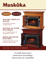
MTVS2500SCH
Assembly Instructions
Instructions d’assemblage
Instrucciones de montaje
Electric Fireplace
Holds up to a 55” flat panel television
Foyer Électrique
Le support de TV supportent un
télévision plat jusqu’à 55”
Chimenea Eléctrica
El soporte de Televisión sostiene hasta
un televisor de pantalla plana de 55“
save These InsTrucTIons
conserver ces InsTrucTIons
guarde esTas InsTruccIones
11
YEAR
AN
AÑO
I
N
H
O
M
E
W
A
R
R
A
N
T
Y
G
A
R
A
N
T
I
E
À
L
A
M
A
I
S
O
N
G
A
R
A
N
T
Í
A
E
N
S
U
P
R
O
P
I
A
C
A
S
A

1
Part Description Qty. Part #
A Right Side Panel Interior 1
ZZ.2500SCH.01
B Left Side Panel Interior 1
ZZ.2500SCH.02
C Central Shelf 1
ZZ.2500SCH.03
D Base 1
ZZ.2500SCH.04
E Exterior Panel 2
ZZ.2500SCH.05
F Central Shelf Trim Piece 1
ZZ.2500SCH.06
G Back Panel 2
ZZ.2500SCH.07
H Storage Back Panel 1
ZZ.2500SCH.08
Part Description Qty. Part #
I Top 1
ZZ.2500SCH.09
J Shelf 4
ZZ.2500SCH.10
K Right Side Door 1
ZZ.2500SCH.11
L Left Side Door 1
ZZ.2500SCH.12
M Interior Panel Trim Piece 2
ZZ.2500SCH.13
N Firebox Brace 1
ZZ.2500SCH.14
O Base Support 1
ZZ.2500SCH.15
I
C
H
D
G
E
G
B
A
J
E
L
J
J
J
K
N
O
M
M
F
TIPS FOR THE ASSEMBLY OF YOUR NEW MANTEL
Before you begin assembly, locate the instructions and hardware. Take out all the parts and compare
them to the diagrams below. Be sure you have all the parts and can identify them.
A helping hand is always good. Assemble your mantel with an adult assistant if possible. Some pieces
are heavy and will need to be held by a helper. Assembly time will take approximately 30-60 minutes.

2
HARDWARE
AA BB CC DD EE
Cam
Lock Dowel
Qty. 32
Cam Lock
Qty. 32
HH
Handle
Qty. 2
FF
Plastic Cam
Cap
Qty. 32
Mounting
Bracket
Qty. 2
Nylon Strap
Qty. 1
II JJ KK LL
Mounting
Peg
Qty. 16
Small Screw
Qty. 19
Large
Screw
Qty. 1
Wall
Anchor
Qty. 1
Back Panel
Screws
Qty. 44
Handle
Screw
Qty. 4
MM
Touch-Up
Pen
Qty. 1
PP
NN
Door
Hinge
Qty. 4

Step 1
Locate the central shelf trim piece (F). Insert 3 cam
lock dowels (AA) into the holes on the back of the
trim piece. The back side is the unfinished side.
Locate the central shelf (C). Make sure the central
shelf finished side is facing up with the mouse hole
at the back. Insert 3 cam locks (BB) into the holes
on the underside of the central shelf (C). Make
sure the arrows on the cam locks (BB) are pointing
towards the trim piece. Line up the cam lock dowels
(AA) in the trim piece with the holes on the front
edge of the central shelf (C). Push together the
trim piece (F) and the central shelf (C) until flush.
Tighten cam locks (BB). Do not strip the cam locks
by overtightening them.
Place cam caps (CC) over the 3 cam locks.
Step 2
Locate the left side panel interior trim piece (M).
Insert 3 cam lock dowels (AA) into the holes on
the back of the trim piece (M). The back side is the
unfinished side.
Locate the left side panel interior (B). Make sure
the left side panel interior (B) finished side is facing
out with the mouse hole at the bottom. Insert cam
locks (BB) into the holes on the right side of the left
side panel interior (B). Make sure the arrows on
the cam locks (BB) are pointing towards the trim
piece (M). Line up the cam lock dowels (AA) in the
trim piece (M) with the holes on the edge of the left
side panel interior (B). Push together the trim piece
(M) and the left side panel interior (B) until flush.
Tighten cam locks (BB). Do not strip the cam locks
by overtightening them.
Repeat for the right side panel interior (A).
Place cam caps (CC) over the 6 cam locks.
3
GET READY TO START
Before assembly, use scissors to unwrap the parts from the packaging. DO NOT use a box cutter or
exacto-knife as you may cut into the mantel pieces inside the box and damage the finish. Check for the
hardware bag located inside the packaging, taped to the top box. Be sure you DO NOT discard any
pieces.
Hardware Used
AA Cam Lock Dowels x 3
BB Cam Locks x 3
CC Cam Cap x 3
Hardware Used
AA Cam Lock Dowels x 6
BB Cam Locks x 6
CC Cam Cap x 6
AA
BB
CC
AA
BB
CC

4
Step 3
Locate the base (D). Insert 3 cam lock dowels (AA)
into the holes under the base (D). Locate the base
support (O). Insert 3 cam locks (BB) into the holes
on the front of the base support (O). The backside
is the unfinished side. Make sure the arrows on the
cam locks (BB) are pointing up toward the base
(D). Push together the base support (O) and the
base (D) until flush. Tighten cam locks (BB). Do not
strip the cam locks (BB) by overtightening them.
Place cam caps (CC) over the 3 cam locks (BB).
Step 4
Locate the left side panel interior (B). Insert 2 cam
lock dowels (AA) into the holes on the inside of
the left side panel interior (B). Insert 2 cam locks
(AA) into the underside of the central shelf (C).
Make sure the arrows on the cam locks (BB) are
pointing towards the left side panel interior (B).
Push together the left side panel interior (B) and
the central shelf (C) until flush. Tighten cam locks
(BB). Do not strip the cam locks by overtightening
them.
Repeat for the right side panel interior (A).
Place cam caps (CC) over the 4 cam locks (BB) on
the underside of the central shelf.
Hardware Used
AA Cam Lock Dowels x 3
BB Cam Locks x 3
CC Cam Cap x 3
Hardware Used
AA Cam Lock Dowels x 4
BB Cam Locks x 4
CC Cam Cap x 4
AA
BB
CC
AA
BB
CC

Step 5
Insert 8 cam lock dowels (AA) into the 8 holes
shown on the base (D). Insert 2 cam locks (BB)
into the bottom outside of each of the left and
right side panel interiors (B & A). Insert 2 cam
locks (BB) into the bottom inside of each of the left
and right side panel exteriors (E). Make sure the
cam lock arrows are pointing down toward the
base.
Push all 4 panels down onto the base (D) until
flush. Tighten cam locks (BB). Do not strip the cam
locks by overtightening them.
Place cam caps (CC) over the 8 cam locks (BB).
Step 6
Locate the top (I). Make sure the finished side
is up. Insert 8 cam lock dowels (AA) into the
holes on the underside of the top (I). Insert 2 cam
locks (BB) on the top inside of the left side panel
exterior (E) and the left side panel interior (B).
Repeat for the right side panel interior (A) and the
right side panel exterior (E). Make sure all cam
lock arrows are pointing upward toward the
top (I).
Make sure the cam lock dowels (AA) line up with
the holes on the top of the interior and exterior
panels (A, B & E). Push the top (I) down until flush.
Tighten cam locks (BB). Do not strip the cam locks
by overtightening them.
Insert 16 mounting pegs (DD) on the inside of the
left and right side storage areas.
5
Hardware Used
AA Cam Lock Dowels x 8
BB Cam Locks x 8
CC Cam Cap x 8
AA
BB
CC
E
Hardware Used
AA Cam Lock Dowels x 8
BB Cam Locks x 8
CC Cam Cap x 8
DD Mounting Pegs x 16
AA
BB
CC
DD
E

Step 7
Locate the 2 back panels (G) and the storage back
panel (H). Make sure the finished sides of the
panels face in toward the mantel. Line up a back
panel (G) so it is flush to the back of the left side
panel interior (B) and left side panel exterior (E).
Secure with 12 back panel screws (MM) - 5 down
each side and 1 at the top and bottom. Tighten
until secure. Repeat for the other back panel (G).
Line up the storage back panel (H) so it is flush to
the back of the left and right side panel interiors
(A and B) and the top (I). Secure with 10 back
panel screws (MM) - 4 across the top and bottom
and 1 on each side. Tighten until secure.
Step 8
Locate the 4 shelves (J). Place the shelves (J) on the
mounting pegs (DD) in each storage area. Make
sure the shelves are level.
6
G
G
H
MM
Hardware Used
MM Back Panel Screws x 34

Step 9
Locate the left door (L). Place the rounded part of
the door hinge (NN) into the recessed area on
the left door (L). Using 2 small screws (EE), secure
the hinge to the door. Line up the left door (L) and
the hinge with the holes on the inside of the left
side panel exterior (E). Using 2 small screws (EE),
secure the door hinge (NN) to the left side panel
exterior (E). Repeat for the other door hinge on the
left door. Tighten all the small screws (EE) on both
door hinges until secure. Repeat for the right side
door (K).
Note: If the doors need leveling, adjust the 2
screws on the door hinge as needed.
Locate a handle (FF). Line up the holes in the
handle (FF) with the holes in a door. Insert 2
handle screws (LL) through the door and into
the handle (FF). Tighten handle screws (LL) until
secure. Repeat for the other handle (FF).
Step 10
Trim pieces for the firebox insert are provided
to close any gaps between the insert and the
mantel. Attach the firebox insert trim pieces to
firebox insert using 2 screws (MM) on the top and
2 sides. Once the trim pieces are secure, slide
firebox insert into the mantel from the back. Once
the firebox is in place and square with the mantel
opening, secure the 2 side firebox insert trim
pieces to the mantel using 2 screws (MM) on each
piece.
NOTE: If there is no room to get a screwdriver
between the insert and the mantel, the screws do
not have to be attached to the mantel. The firebox
insert will be secured in the next step. The trim
pieces are for appearance only.
7
FF
LL
EE
EE
x8
x8
NN
Hardware Used
FF Handle x 2
LL Handle Screw x 4
EE Small Screw x 16
NN Door Hinge x 4
MM
MM
MM
Hardware Used
MM Small Screw x 10

8
Step 11
Locate the firebox insert. Insert the firebox from
the rear of the mantel assembly. Once the firebox
insert is in place and secure, locate the firebox
brace (N). Place the firebox brace (N) up against
the firebox insert making sure you don’t cover any
air venting. Once the firebox brace (N) is snug,
secure it to the base (D) using 2 small screws (EE).
Your fireplace insert is now sitting firmly in place.
You must attach the anti-tipping device to the mantel
and the wall. This device is a safety feature that
will prevent the mantel from tipping over. Applied
weight may cause mantel imbalance.
Step 12
Attach one of the mounting brackets (II) securely to
the back underside edge of the mantel. Use 1 small
screws (EE) to make sure it is secure.
Step 13
Determine where mantel is to be placed and mark
location on the wall for the mounting bracket (II)
screw holes. The mounting bracket (II) on the wall
should be positioned horizontally. Insert a wall
anchor (JJ) into each screw hole in the wall. Place
the mounting bracket (II) over the marks on the wall
and use a large screw (KK) to securely attach the
mounting bracket (II) to wall.
Hardware Used
EE Small Screw x 1
II
Mounting
Bracket
x 1
EDGE OF
MANTEL
BRACKE
T
SMALL
SCREW
EE
I I
Hardware Used
JJ Wall Anchor x 1
KK Large Screw x 1
II
Mounting
Bracket
x 1
JJ
II
KK
WALL
Hardware Used
EE Small Screw x 2
D

9
Step 14
Place the mantel so the mounting bracket (II) on the back of the
mantel is in line with the mounting bracket (II) on the wall. Place an
end of the nylon strap (HH) down through each bracket. Bring both
ends together and slide the end of the nylon strap (HH) through the
slot in the other end until snug. Pull down on the end until it locks
into the slot. Check to make sure the nylon strap (HH) is securely
laced and locked to the mounting brackets (II).
WARNING: Young children may be injured by tipping furniture.
The use of a tipping restraint is highly recommended. This
hardware, when properly installed, could provide protection
against the unexpected tipping of furniture due to improper use.
WARNING: THIS PRODUCT IS ONLY A DETERRENT. IT IS NOT
A SUBSTITUTE FOR PROPER ADULT SUPERVISION.
CAUTION:
This unit is intended for use only
with the products and maximum weights
indicated. Use with other products or products
heavier than the maximum weights indicated
may result in instability causing possible injury.
Note: Flat Panel TVs with base support should
be placed squarely in the center of the stand
with no overhang on any side.
Hardware Used
HH Nylon Strap x 1
CARE AND MAINTENANCE
1. Dust your fireplace mantel regularly with a soft non-lint producing cloth or household dusting
product.
2. You can clean your fireplace insert with a gentle non-abrasive household cleaner. Make sure to dry it
immediately with a soft cloth or towel.
This mantel comes with a touch up pen for any minor repairs.
FIT UP TO 55" PLASMA/
LCD TELEVISIONS
MAXIMUM LOAD
90 lb. (40.8 kg)
MAXIMUM LOAD
30 lb. (13.6 kg)
MAXIMUM LOAD
5 lb. (2.3 kg)
GG
WALL
MANTEL

WARRANTY
Greenway Home Products is pleased to offer in-home warranty repairs. Please refer to your Firebox Use and Care Guide for warranty
information on your Firebox.
DO NOT RETURN THIS PRODUCT TO THE STORE:
Please contact Customer Service at: 1-866-253-0447
Monday to Thursday from 8:30AM to 5:00PM (EST), Friday from 8:30AM to 4:00PM (EST)
Web: www.greenwayhp.com
Email: support@greenwayhp.com
Canada: 400 Southgate Dr., Guelph, Ontario, Canada, N1G 4P5
USA:
1270 Flagship Dr., Perrysburg, Ohio, USA, 43551
Limited Warranty Definitions:
Greenway Home Products:
(Greenway) Manufacturer.
Mantel: Mantel manufactured by Greenway Home Products.
Purchaser: Purchaser of the Mantel
Distributor: Facility authorized to sell Greenway Home Products.
Warranty Card Greenway Home Products Limited Warranty Registration Card identifying the Purchaser and product model.
Greenway Limited Warranty:
Greenway warrants to the Purchaser that the Mantel is free from defects in material and workmanship, under normal use and service, for
1 year (1 year limited parts) from the date of purchase.
All warranty repairs must be preauthorized by Greenway Home Products. Greenway will, at its’ option, replace or repair free of charge
any defective part, which the Purchaser shall notify their Distributor or Greenway Home Products within the warranty period. The obligation
of Greenway Home Products under this warranty, is expressly limited to such replacement or repairs.
The provisions of this limited warranty shall not apply to the following:
1. Accidents.
2. Unauthorized repairs or alterations.
3.
Normal maintenance.
4. Changes made to other units manufactured after this mantel was manufactured.
5. Incidental damages caused by failure of the mantel such as inconvenience or loss of use.
6.
Improper installation.
The provisions of this limited warranty shall not apply to deterioration due to wear and exposure beyond the following limitations:
1. For 180 days from the date of purchase for exterior finished surfaces.
Due to the properties of natural wood, Greenway Home Products makes no warranty against mineraling of wood components.
Greenway Limited Warranty is void unless the following conditions are adhered to:
1. Warranty registration must be completed and returned to a Greenway Home Products.
2. All warranty repairs must be preauthorized by a Greenway repair facility.
3. Greenway reserves the right to inspect defective parts that have been replaced under warranty. Dealer is expected to hold
defective parts for 60 days.
4. Only parts and accessories and other materials, available through Greenway Home Products are to be used in the performance
of warranty service.
5. Purchasers are responsible for presenting/notifying their Distributor as soon a problem exists. The warranty repairs should be
completed in a reasonable amount of time from the date of authorization. Not to exceed 30 days past notification.
This limited warranty is expressly in lieu of any other expressed or implied warranty, including any implied warranty or merchantability
or fitness for a particular purpose and of any obligations or liabilities on Greenway Home Products which neither assumes nor
authorizes any other person to assume for it any other liability in connection with the Mantel manufactured by it.
The warranty is null and void if used in commercial or industrial applications.
10
/


