GB743
INSTALLATION TOOL
GAGE BILT
MADE IN U.S.A.
GAGE BILT Inc.
44766 Centre Court (586) 226-1500
Clinton Twp. MI 48038 (586) 226-1505 Fax
GAGE BILT TOOLS ARE AVAILABLE WORLDWIDE
E-MAIL US FOR A DISTRIBUTOR NEAR YOU.
S/N: 2269 AND ABOVE
PLEASE CONTACT GAGE BILT FOR
ALL OTHER SERIAL NUMBERS.

2
REV. 10/14
S/N: 2269 AND ABOVE
PLEASE CONTACT GAGE BILT FOR ALL OTHER SERIAL NUMBERS.
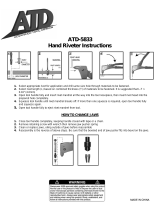
SPECIFICATIONS
Hand Held Weight - 6.25 lbs. (2.83 kg)
Air pressure req'd - 90-100 p.s.i. (6.2-6.9 bar)
Air consumption - .29 SCF/cycle (8.21 L/cycle)
Hydraulic oil - Automatic Transmission Oil,
Dexron® III, or equivalent.
Setting stroke - .900" (22.86mm)
Rated pull load - 4,000 lbs. (17.8 kN)
Noise level - Less than 81.5 dB (A)
Vibration - Tested-No hazards found.
9.00
(228.6mm)
6.74
(171.1mm)
2.95
(74.9mm)
.87 Ø
(22.1mm)
2.25
(57.1mm)
6.17
(156.7mm)
4.74
(120.3mm)
4.88 Ø
(123.9mm)
1.84
(46.7mm)
1.50
(38.1mm)
1.94 Ø
(49.2mm)
1.36 Ø
(34.5mm)
TABLE OF CONTENTS
Description Page
Warnings ................................................................................................................................... 3
Principle of Operation .............................................................................................................. 4
How to use the GB743 ............................................................................................................. 5
Description, Operation and Maintenance ............................................................................... 6
Filling, Bleeding and Troubleshooting ................................................................................... 7
Overhaul .................................................................................................................................... 8
Disassembly and Parts List ............................................................................................... 9-10
DEXRON® III Oil Safety Data ..................................................................................................... 11
Nose Assembly Selection Chart ........................................................................................... 12
EU Conformity and Warranty ................................................................................................ 13

3
REV. 10/14
S/N: 2269 AND ABOVE
PLEASE CONTACT GAGE BILT FOR ALL OTHER SERIAL NUMBERS.
WARNING
Do not pull fastener unless it is placed in an
assembly, pin will eject forcibly when pintail breaks
off. Severe personal injury may result.
WARNING
Do not operate without Stat-O-Seal (S572) and cap
screws (402482). Pressurized hydraulic oil may
cause severe personal injury.
WARNING
When operating, repairing or overhauling tool, wear
approved eye protection. Do not look in front of
nose assembly or rear of tool when installing
fastener.
WARNING
Always disconnect tool from power source before
performing any maintenance to any tool or nose
assembly.
WARNING
Do not operate if deflector, bottle, catcher bag or
vacuum tube is removed or damaged, broken
pintails may eject forcibly from rear of tool. Severe
personal injury may result.
CAUTION
Ensure that nose assembly and tip are properly
matched for the fastener being installed.
CAUTION
Keep Nose Assemblies clean and free of chips and
debris.
WARNING
Be sure there is adequate clearance for tool and
operator's hands before proceeding. Keep fingers
clear of any moving parts. Keep fingers clear from
fasteners and installed materials. Severe personal
injury may result.
WARNING
It is required to use hearing protection. A test was
carried out in a simulated work environment where
the background level was 73.2 dB (A). In this
condition the max level was 81.5 dB (A). Therefore,
it is required where prolonged use, hearing
protection be used.
CAUTION
Do not use beyond the design intent.
WARNING
Tool must be maintained in a safe working
condition at all times and examined on a daily basis
for damage or wear. Any repair should be done by
qualified personnel trained on Gage Bilt
procedures.
WARNING
Where prolonged use is foreseen, it is
recommended a tool balancer be used. Check
suspension device to ensure that it is secure.
WARNING
Do no use tool in explosive atmosphere.
CAUTION
Tool is not to be used as a hammer.
WARNING
Risk of crushing exists if nose assembly is not
attached.
WARNING
It is recommended tool be operated 50 out of every
60 minutes, where prolonged use is expected.
WARNING
Shock:
It is recommended operator wear a suitable glove
during operation where prolonged use is expected.
WARNING
Air pressure not to exceed 100 psi (6.9 bar).
SAFETY WARNINGS
PLEASE READ THIS MANUAL BEFORE
SERVICING OR USING THIS TOOL.
WARNINGS:
MUST BE UNDERSTOOD TO AVOID
SEVERE PERSONAL INJURY
CAUTIONS:
SHOW CONDITIONS THAT WILL
DAMAGE EQUIPMENT OR STRUCTURE
WARNING
Ensure that all connections are properly secured
before connecting to power.

4
REV. 10/14
S/N: 2269 AND ABOVE
PLEASE CONTACT GAGE BILT FOR ALL OTHER SERIAL NUMBERS.
PRINCIPLE OF OPERATION
When the air actuator assy is depressed, the pressurized air inside of the tool is released allowing spring pressure to move the valve
spool assy causing the air to be redirected. The air is directed to the top of the air piston assy, moving it in a downward direction.
The air below the air piston assy is then directed through the valve sleeve and exhausted out of the bottom of the tool.
Simultaneously, the piston rod assy connected to the air piston assy is also moving down, forcing hydraulic oil up and into the front
side of the head cylinder assy, causing the piston to move to the rear of the head cylinder assy. The internal components of the
attached nose assembly are also moving with the piston to start the fastener installation. When the fastener installation is
completed, the air actuator assy is released. Air pressure is then built up inside of the handle assy causing the valve spool assy to
return to its original position and reversing the sequence directing air pressure to the rear of the head cylinder assy, causing the
piston to move to the forward position.
Image may not reflect actual tool

5
REV. 10/14
S/N: 2269 AND ABOVE
PLEASE CONTACT GAGE BILT FOR ALL OTHER SERIAL NUMBERS.
HOW TO USE THE GB743
WARNING: Operator MUST read and understand all warnings and cautions.
WARNING: It is required that eye protection and hearing protection be worn during operation.
WARNING: Do not pull rivet in the air. Personal injury from fastener ejecting may occur.
WARNING: Air is exhausted from the bottom of the too. Direct bottom of the tool (exhausted air) away from operator, other
persons working in the vicinity, foreign matter and liquid.
CAUTION: Do not use beyond the design intent.
The tool is shipped with a plastic plug in the air inlet connector. The connector has a 1/4-18 female pipe thread to accept end-user air
hose fitting. The tool comes with oil and is ready to use.
1. Remove plastic shipping plug from Swivel (A-249) and screw in your air fitting.
2. Attach Deflector (200232) to rear of Head Cylinder Assy (743108).
WARNING: Rotate deflector away from operator and other persons working in the vicinity.
3. Connect air hose to tool (3/8 minimum diameter air line is mandatory, 90 p.s.i. (6.2 bar) is recommended) and cycle tool a few
times by depressing and releasing air actuator assy (704130). (Clean dry air is mandatory).
WARNING: Ensure air hose is securely connected to avoid possible hose whipping.
4. Disconnect air hose from tool.
5. Select proper Nose Assembly, screw collet and anvil onto the tool and attach securely. (See proper data sheet for further
instructions.)
6. Connect air supply.
7. Insert rivet into Nose Assembly and the application then depress air actuator assy (704130). Upon releasing the air actuator assy
(704130) the stem will eject to the rear of the tool.
WARNING: Always disconnect air supply when tool is not in use to prevent accidental start-up.
DEFLECTOR
HEAD
CYLINDER
ASSY
NOSE
ASSEMBLY
RIVET
WORK
RED
SHIPPING
PLUG
QUICK
DISCONNECT
FITTING
AIR
ACTUATOR
ASSY
Image may not reflect actual tool

6
REV. 10/14
S/N: 2269 AND ABOVE
PLEASE CONTACT GAGE BILT FOR ALL OTHER SERIAL NUMBERS.
TORQUE SPECIFICATIONS
Button Head Cap Screws (402479) = 40 inch lbs.
Packing Plug (744118) = 45 foot lbs.
Flexlock Nut (400559) = 40 inch lbs.
End Cap (743214) = 45 foot lbs.
Button Head Cap Screws (402482) = 35-40 inch lbs. (Do NOT over-tighten)
DESCRIPTION
WARNING: The balance of this tool is designed for horizontal use and is not ergonomically best suited for all applications.
Gage Bilt will be pleased to advise for your specific application.
The GB743 is a pneumatic-hydraulic tool designed specifically for the efficient installation of a wide range of blind rivets. It weighs
6.25 lbs. (2.83 kg) and can be operated in any position with one hand. It has a .900" (22.86mm) rivet setting stroke and a rated pull load
of 4000 lbs. (17.8 kN) with 90 psi (6.2 bar) air pressure at the air inlet.
The GB743 riveter operates on a wide range of air pressure, with 90 to 100 psi (6.2-6.9 bar) providing the maximum efficiency. At 90
psi. (6.2 bar) air pressure, the GB743 does not exceed 81.5 dB (A) and consumes 3 cfm at 20 cycles a minute.
The air inlet is provided with 1/4-18 female pipe threads to accept the users air hose fitting.
UNLESS ORDERED RIVET SPECIFIC (I.E. GB743/8N), THE STANDARD GB743 IS FURNISHED WITH NOSE ASSEMBLY 8N-743-24 AND
A SPARE NOSE TIP 10204 TO CONVERT TO A 6N-743-24. ALL OTHER NOSE TIPS MUST BE ORDERED SEPARATELY. WHEN
ORDERING TOOL RIVET SPECIFIC, PLEASE CONTACT GAGE BILT FOR MORE INFORMATION.
CLEANING AND LUBRICATING PROCEDURE
Daily cleaning and lubrication of nose assembly will greatly reduce downtime and
increase life of components. Using sewing machine oil, or an equivalent cleaner/
lubricant, follow instructions below.
1. Disconnect tool vacuum line (if equipped).
2. Point nose assembly into oil as shown.
3. Cycle tool 8-10 times and wipe dry.
Image may not reflect
actual tool.
MAINTENANCE
WARNING: Maintenance personnel MUST read and understand all warnings and cautions.
WARNING: Disconnect tool from its power source before performing maintenance.
WARNING: Excessive contact with hydraulic oil and lubricants should be avoided.
WARNING: Dispose of hydraulic oil in accordance with all environmental regulations applicable in your area.
WARNING: Read MSDS documents for all applicable materials.
The performance of any tool depends upon good maintenance practices. Following these minimal requirements for service and care
will extend the life of your tool.
*Only use an air supply set at 90-100 p.s.i. (6.2-6.9 bar) equipped with a filter-regulator to prevent wear.
*The tool will eventually lose some hydraulic oil. Keep the hydraulic system full (only use Dexron III or equivalent) and free of air by
using the air bleeder assy (704153) on a weekly basis.
*Proper care by operator is necessary in maintaining full productivity and reducing downtime. Read all
applicable tool manuals and nose assembly data sheets prior to operating tools.
*Keep nose assemblies, especially jaws, clean and free of chips and debris. Lube jaws and collet surfaces that jaws ride on with light
machine oil on a daily basis.
*All Screwed End Caps, Base Covers, Air Fittings, Air Actuators, Screws and Nose Assemblies are to be examined at the end of each
working shift to check that they are secure.
*Check tool, all hoses and all couplings daily for damage or air/hydraulic leaks. Tighten or replace (if necessary).
*For a complete overhaul, tool kit GB704TK is recommended (see page 8).

7
REV. 10/14
S/N: 2269 AND ABOVE
PLEASE CONTACT GAGE BILT FOR ALL OTHER SERIAL NUMBERS.
FILLING AND BLEEDING TOOL
NOTE: Air bleeder assy (704153) is required.
WARNING: Do not cycle tool without air bleeder assy (704153), or the button head cap screw (402482) and stat-o-seal (S572),
installed in the head cylinder assy (743108). Severe personal injury may result.
CAUTION: Before filling handle assy (744129), the air piston assy (744121) should be all the way down.
CAUTION: When forcing piston rod assy (744136) downward with head cylinder assy (743108) removed, hydraulic oil will
eject forcibly from handle assy (744129).
CAUTION: Use CAUTION when removing button head cap screws (402482), stat-o-seals (S572) and air bleeder assy (704153).
Hydraulic oil may be under pressure.
WARNING: Failure to follow these instructions carefully may result in severe personal injury
To replace a small amount of oil in the tool, attach the air bleeder assy and connect tool to air line. Cycle tool ten times. Disconnect
air, remove the air bleeder assy, and reinstall the cap screw. This will ensure the removal of any air from the hydraulic system and its
replacement with oil.
* FILLING & BLEEDING VIDEO AVAILABLE AT: www.gagebilt.com/bleeding.htm
Should it become necessary to completely refill the tool (such as would be required after tool has been dismantled and reassembled),
take the following steps after depressing air actuator assy AND DISCONNECTING THE AIR SUPPLY:
1. Remove (4) button head cap screws (402479) and head cylinder assy (743108) from handle assy (744129). Slowly push piston (743407)
completely forward. CAUTION: Oil may leak from bottom of head cylinder assy (743108).
2. Fill handle assy (744129) and the oil passage on top of handle assy (744129) with automatic transmission oil, Dexron III or
equivalent. When looking at the top of the handle assy (744129) , the oil passage is the hole that is counterbored for o'ring (S832).
3. Replace head cylinder assy (743108) with care, ensuring gasket (704129) and o'ring (S832) are properly installed. Apply Loctite
242 to all four button head cap screws (A-928) and torque uniformly to 40 inch lbs. to prevent leakage around gasket (704129).
4. Remove button head cap screw (402482) and stat-o-seal (S572) from head cylinder assy (743108). Install air bleeder assy
(704153) and connect tool to air line, cycle ten to twenty times to fully circulate oil through hydraulic system.
5. DISCONNECT AIR FROM TOOL. Remove air bleeder assy (704153), install button head cap screw (402482) and stat-o-seal (S572)
on head cylinder assy (743108) and torque to 40 inch lbs.
6. Connect air supply. Cycle tool ten times and check stroke of .900" (22.86mm) min. (see diagram below). We recommend using a
pair of dial calipers. With the air actuator assy (704130) released, check dimension (A). With the air actuator (704130) depressed
check dimension (B). If stroke is not consistent within 1/64" (.0156) repeat bleeding steps 4-6.
TROUBLESHOOTING
Providing all maintenance conditions have been met, follow this systematic approach to diagnosis.
1. MORE THAN ONE PULL IS REQUIRED TO BREAK RIVET.
a) Tool needs to be bled. (See filling and bleeding instructions.)
b) Spring has fatigued, replace.
c) Jaws are stripped or packed with chips. Clean or replace.
2. SLOW OR PARTIAL OPERATION WHEN THE AIR ACTUATOR ASSY IS DEPRESSED
a) Polyseal (A-1135) and O’Rings (400792) on piston (743407) could be worn or damaged. Replace.
b) Back-up ring (S908) and O’Ring (A-201) on piston rod assy (744136) could be worn or damaged. Replace.
c) Muffler (744143) or filter inside valve spool assy (743142) may be plugged with dirt. Clean thoroughly and back-blow with
compressed air.
d) Hole in metering screw in valve spool assy (743142) may be blocked or damaged. Hole diameter should be .028". Clear
and size or replace.
3. NO OPERATION WHEN AIR ACTUATOR ASSY IS DEPRESSED
a) Tool seized due to mechanical failure or damaged parts.
4. OIL LEAKAGE
a) DO NOT OPERATE WITH OIL LEAKING FROM TOOL. HIGH PRESSURE OIL MAY CAUSE SEVERE PERSONAL INJURY.
b) Any oil leaking externally should be traced to its source. An o'ring or seal that leaks should be replaced.
5. AIR BYPASS FROM VALVE HOUSING
a) If the spring (744144) breaks or dislodges, air will flow freely through the muffler (744143). Replace or reset. Valve spring
installation tool (744151) is recommended.
b) Check o'rings on valve sleeve (743144), valve spool assy (743142), and valve plug (744142). If worn or damaged, replace.
Valve sleeve removal tool (744152) is recommended.
6. FASTENER STEM JAMMED IN NOSE ASSEMBLY
a) Nose assembly components require service. DISCONNECT AIR FROM TOOL, remove the nose from the tool and
disassemble. Replace worn or broken parts. Clean the surface the jaws ride on.
b) Stems lodged side by side in the follower. Disassemble, remove stems, and reassemble.
c) Incorrect follower.
(A)
1.126 (28.6mm)
(B)
.226 (5.7mm)

8
REV. 10/14
S/N: 2269 AND ABOVE
PLEASE CONTACT GAGE BILT FOR ALL OTHER SERIAL NUMBERS.
OVERHAUL
WARNING: Disconnect tool from its air source before performing overhaul.
WARNING: Tool must be maintained in a safe working condition at all times and examined on a daily basis for damage or
wear. Any repair should be done by qualified personnel trained on Gage Bilt procedures.
WARNING: When operating, repairing or overhauling tool, wear approved eye protection. Do not look in Front of tool or
rear of tool when installing fastener.
WARNING: Depress lever assy and disconnect from air, with the piston in the rear position, before overhaul.
Severe personal injury may occur if air hose is not disconnected. USE CAUTION when forcing piston
rod assy downward with head cylinder assy removed. Hydraulic oil will eject forcibly from handle assy.
The disassembly and re-assembly procedure can be accomplished by utilizing the following instructions and drawings. Use extreme
care during disassembly and re-assembly not to mar or nick any smooth surface that comes in contact with seals. Before installing
seals, always apply a good lubricant, such as Lubriplate, to the surfaces. It is recommended that tool kit (GB740TK) be used to
facilitate overhaul. A complete overhaul can be achieved by the use of Service Kit (743018) which contains a complete set of o'rings,
back-up rings, screws, washers and gasket. It is recommended that this service kit be kept available for spare parts.
(704214 CATCHER BAG SHOWN ABOVE IS SOLD SEPARATELY)
704214 STEM CATCHER BAG
704149
PISTON ROD WRENCH
704151
POWER CYLINDER TOOL
704152
SEAL GUIDE
704150
PACKING PLUG WRENCH
704153
BLEEDER BOTTLE
744251
VALVE SPRING
INSTALLATION TOOL
744152
VALVE SLEEVE
REMOVAL TOOL
S1178
VALVE EXTRACTOR
Part No. Description
704149 Piston Rod Wrench
704150 Packing Plug Wrench
704151 Power Cylinder Tool
704152 Seal Guide
704153 Air Bleeder Ass'y
S1178 Valve Extractor
744251 Valve Spring Installation Tool
744152 Valve Sleeve Removal Tool
GB740TK Service Tool Kit Includes:

9
REV. 10/14
S/N: 2269 AND ABOVE
PLEASE CONTACT GAGE BILT FOR ALL OTHER SERIAL NUMBERS.
HEAD
WARNING: Dispose of hydraulic oil in accordance with all environmental regulations applicable in your area.
Remove nose assembly from tool before attempting disassembly of head assembly.
Remove end cap (743214). Push against threaded end of piston (743407) to slide it out of head cylinder assy (743108). Be careful not
to damage threads or cause burrs on polished piston (743407) surface.
The re-assembly sequence is the opposite of disassembly. (See Filling and Bleeding instructions.) Apply Loctite® #242 and torque the
four button-head cap screws (402479) uniformly to 40 inch lbs. to prevent leakage around the gasket (704129).
S834 - O'RING
401089 - BACK-UP RING
S834 - O'RING
743407 - PISTON
A-1135 - POLYSEAL
400792 - O'RING
S829 - O'RING
743214 - END CAP
200232 - DEFLECTOR
402482
BUTTON HEAD CAP SCREW
S572 - STAT-O-SEAL
743108
HEAD CYLINDER ASSY
400792 - O'RING
SEAL IN POLYSEAL
MUST FACE IN THIS
DIRECTION

10
REV. 10/14
S/N: 2269 AND ABOVE
PLEASE CONTACT GAGE BILT FOR ALL OTHER SERIAL NUMBERS.
HANDLE
To inspect air cylinder bore, remove o’ring (S12) and base cover (744124). Any further disassembly will require removal of the head
cylinder assy (743108) first. For complete disassembly, start by removing o’ring (S12) and base cover (744124). Next, holding tool
upright, remove four button-head cap screws (402479). Lift head cylinder assy (743108) from handle assy (744129) and set aside
o'ring (S832) and gasket (704129). Empty all hydraulic oil into an approved container and dispose of in accordance with all
environmental regulations applicable in your area. Place piston rod wrench (704149) down into top of power cylinder (743131), into
the hex of piston rod assy (744136). While holding this wrench, remove flexlock nut (400559) using a 7/16" socket wrench. Still
holding piston rod wrench (704149), remove air piston assy (744121) using packing plug wrench (704150), by turning counterclockwise.
When air piston assy (744121) is completely free from piston rod assy (744136), tap or push on the piston rod wrench (704149), to
eject air piston assy (744121) from bottom of handle assy (744129). After removal of air piston assy (744121), slide piston rod assy
(744136) back up to the end of its travel. Using packing plug wrench (704150) remove packing plug (744118). With packing plug
removed, power cylinder (743131) can be removed by pushing on power cylinder tool (704151) when inserted into top of power
cylinder (743131).
To reassemble the handle assy (744129), reverse the above procedure, being certain that all o'rings are properly lubricated before
installation. Torque packing plug (744118) to 45 foot lbs. Attach the seal guide (704152) to the piston rod assy (744136) and tap the
piston rod assy (744136) through the packing plug (744118). Attach air piston assy (744121) and flexlock nut (400559), torque
flexlock nut (400559) to 40 inch lbs. With the piston rod assy (744136) in the down position, fill oil passage on top of handle assy
(744129) with automatic transmission oil, Dexron III or equivalent, when looking at top of handle assy (744129) the oil passage is the
hole that has a counterbore for o'ring (S832). Replace gasket (704129) and o'ring (S832) just prior to replacing head cylinder assy
(743108). (See Filling & Bleeding instructions.)
AIR VALVE
WARNING: Disconnect tool from its air source before disassembly.
To disassemble, first disconnect tool from its air source. Remove pin (744149) and muffler (744143). Insert valve extractor (S1178)
into end of valve plug (744142) and pull it out. Using the same procedure, pull out valve spool assy (743142). NOTE: It should never
be necessary to remove valve sleeve (743144) unless the ports in the valve sleeve (743144) are plugged from contaminated air. If
ports are plugged, use needle nose pliers to grasp end of spring (744144), turning clockwise and pulling to dislodge from groove in
casting. NOTE: Valve spring (744151) tool will facilitate the proper installation of the spring (744144), valve sleeve (743144) can be
pulled out using valve sleeve removal tool (744152).
S885 - RETAINING RING
S832 - O'RING
744136
A-201 - O'RING
743131 - POWER
S908 - BACK-UP RING
S892 - O'RING
403805 - O'RING
743142 - VALVE SPOOL
744149 - PIN
744142 - VALVE PLUG
400785 - O'RING
744143 - MUFFLER
400785 - O'RING
743144 - VALVE
400779 - O'RING
744144 - SPRING
400784 - O'RING
744129 - HANDLE ASSY
704129 - GASKET
A-249 - SWIVEL
744118 - PACKING PLUG
744124 - BASE COVER
S12 - O'RING
400559 - FLEXLOCK NUT
744121 - AIR PISTON
S909 - BACK-UP RING
401462 - QUAD RING
S909 - BACK-UP RING
A-287 - O'RING
S115 - BACK-UP RING
A-271 - O'RING
S115 - BACK-UP RING
A-287 - O'RING
CYLINDER
PISTON ROD ASSY
(INCLUDES S908 AND A-201)
HEAD CAP SCREW (4)
402479 - BUTTON
SLEEVE
ASSY
ASSY
AIR
ACTUATOR
ASSY
704130

11
REV. 10/14
S/N: 2269 AND ABOVE
PLEASE CONTACT GAGE BILT FOR ALL OTHER SERIAL NUMBERS.
FIRST AID MEASURES
Eye: No specific first aid measures are required. As a precaution, remove contact lenses, if worn, and flush eyes with water.
Skin: No specific first aid measures are required. As a precaution, remove clothing and shoes if contaminated. To remove
the material from skin, use soap and water. Discard contaminated clothing and shoes or thoroughly clean before reuse.
Ingestion: No specific first aid measures are required. Do not induce vomiting. As a precaution, get medical advice.
Inhalation: No specific first aid measures are required. If exposed to excessive levels of material in the air, move the
exposed person to fresh air. Get medical attention if coughing or respiratory discomfort occurs.
Note to Physicians: In an accident involving high-pressure equipment, this product may be injected under the skin. Such
an accident may result in a small, sometimes bloodless, puncture wound. However, because of its driving force, material
injected into a fingertip can be deposited into the palm of the hand. Within 24 hours, there is usually a great deal of
swelling, discoloration, and intense throbbing pain. Immediate treatment at a surgical emergency center is recommended.
FIRE
Leaks/ruptures in high pressure system using materials of this type can create a fire hazard when in the vicinity of ignition
sources (eg. open flame, pilot lights, sparks, or electric arcs).
FLAMMABLE PROPERTIES:
Flashpoint: (Cleveland Open Cup) 178 °C (352 °F) Minimum
EXTINGUISHING MEDIA: Use water fog, foam, dry chemical or carbon dioxide (CO2) to extinguish flames.
PROTECTION OF FIRE FIGHTERS:
Fire Fighting Instructions: This material will burn although it is not easily ignited. See Section 7 for proper handling and
storage. For fires involving this material, do not enter any enclosed or confined fire space without proper protective equipment,
including self-contained breathing apparatus.
Combustion Products: Highly dependent on combustion conditions. A complex mixture of airborne solids, liquids, and
gases including carbon monoxide, carbon dioxide, and unidentified organic compounds will be evolved when this material
undergoes combustion.
ACCIDENTAL RELEASE MEASURES
Protective Measures: Eliminate all sources of ignition in vicinity of spilled material.
Spill Management: Stop the source of the release if you can do it without risk. Contain release to prevent further
contamination of soil, surface water or groundwater. Clean up spill as soon as possible. Use appropriate techniques such
as applying non-combustible absorbent materials or pumping. Where feasible and appropriate, remove contaminated soil.
Place contaminated materials in disposable containers and dispose of in a manner consistent with applicable regulations.
ECOLOGICAL INFORMATION
Waste disposal: In accordance with all environmental regulations applicable to your area.
Spillage: Prevent entry into drains, sewers and water course. Soak up with diatomaceous earth or other inert material.
Store in appropriate container for disposal.
Ecotoxocity: This material is expected to be harmful to aquatic organisms and may cause long-term adverse effects in
the aquatic environment. The ecotoxicity hazard is based on an evaluation of data for the components or a similar material.
HANDLING
Precautionary Measures: DO NOT USE IN HIGH PRESSURE SYSTEMS in the vicinity of flames, sparks and hot
surfaces. Use only in well ventilated areas. Keep container closed. Keep out of the reach of children.
General Handling Information: Avoid contaminating soil or releasing this material into sewage and drainage systems and
bodies of water.
Static Hazard: Electrostatic charge may accumulate and create a hazardous condition when handling this material. To
minimize this hazard, bonding and grounding may be necessary but may not, by themselves, be sufficient. Review all
operations which have the potential of generating and accumulating an electrostatic charge and/or a flammable atmosphere
(including tank and container filling, splash filling, tank cleaning, sampling, gauging, switch loading, filtering, mixing,
agitation, and vacuum truck operations) and use appropriate mitigating procedures.
DISPOSAL CONSIDERATIONS
Use material for its intended purpose or recycle if possible. Oil collection services are available for used oil recycling or
disposal. Place contaminated materials in containers and dispose of in a manner consistent with applicable regulations.
DEXRON® III OIL SAFETY DATA

12
REV. 10/14
S/N: 2269 AND ABOVE
PLEASE CONTACT GAGE BILT FOR ALL OTHER SERIAL NUMBERS.
XX-703-18
XX-734A-20
XX-743-24
SEE CHART
SEE CHART
SEE CHART
10757-1 ANVIL
HOLDER
20518 COLLET SEE CHART
405371
SPRING
70820
NUT
SEE
CHART
10935-1
ANVIL HOLDER
10951-2
ANVIL HOLDER
28819
COLLET
20867
COLLET
SEE
CHART
SEE
CHART
400777
O'RING
SEE
CHART
405371
SPRING
70820
NUT
50626
SPRING
70820
NUT
SEE
CHART
400777
O'RING
RIVET DIA. NOSE ASSEMBLY NOSE TIP JAW FOLLOWER DESIGNATION
3/16 AV6-743-24
1
10248-7 30824 48808 AV6
3/16 6C-743-24
1
10248-8 30824 48808 6C
3/16 BT06-743-24
1
12282-1 30824 48808 BT06
1/4 BT08-743-24
1
10391 30824 48808 BT08
9/32 BT09-743-24
1
10289 30824 40901 BT09
3/16 6KT-743-24
1
10263 30824 48808 6KT
1/4 8KT-743-24
1
10262 30824 48808 8KT
4MM 5N-743-24 1 10203 30824 48808 5N
5MM 6N-743-24 1 10204 30824 48808 6N
3/16 MB06-734A-20 2 - - - MB06
1/4 MB08-734A-20 2 - - - MB08
3/32 3N-703-18 2 - - - 3N
1/8 4N-703-18 2 - - - 4N
5/32 5N-703-18 2 - - - 5N
3/16 6N-743-24
1
10204 30824 48808 6N
1/4 8N-743-24
1
10211 30824 48808 8N
3/32 3N-703-18 2 - - - 3N
1/8 4CEA-703-18 2 - - - 4CEA
5/32 5CEA-703-18 2 - - - 5CEA
3/16 6CEA-743-24
1
13473 30824 48808 6CEA
3/32 3N-703-18 2 - - - 3N
1/8 4CES-703-18 2 - - - 4CES
5/32 5CES-703-18 2 - - - 5CES
3/16 6CES-743-24
1
13477 30824 48808 6CES
1/4 8CES-743-24
1
13469 30824 48808 8CES
3/32 3P-703-18 2 - - - 3P
1/8 4P-703-18 2 - - - 4P
5/32 5P-703-18 2 - - - 5P
3/16 6P-743-24
1
10167 30824 48808 6P
1/4 8P-743-24
1
10166 30824 48808 8P
3/16 6T-743-24
1
10209 30824 48808 6T
1/4 8T-743-24
1
10286 30824 48808 8T
TLR® RIVET
1/4 8TLR-743-24
1
10246 30824 48808 8TLR
3/16 C6-734A-20 2 - - - C6
1/4
C8-734A-20 2 - - - C8
3/16 PH6-734A-20 2 - - - PH6
1/4
PH8-734A-20 2 - - - PH8
1) YOU CAN CHANGE THE 743-24 NOSE ASSEMBLY (INCLUDED WITH TOOL) TO INSTALL OTHER FASTENERS BY PURCHASING
2) NOSE ASSEMBLIES WITH A 703-18 AND 734A-20 DESIGNATION, I.E. 5P-703-18, MUST BE ORDERED AS COMPLETE NOSE ASSEMBLY.
AVEX® (1624 PROTRUDING HEAD)
AVEX (1624 COUNTERSUNKHEAD)
OPEN END
NAIL RIVET
KLAMP-TITE® (STRUCTURAL) RIVET
MONOBOLT® RIVET
T RIVET®
NOTE: THE LAST 2 DIGITS OF THE NOSE ASSEMBLY REPRESENTS THE LENGTH THE NOSE
CLOSED END
NAIL RIVET
(STEEL MANDREL)
CLOSED END
NAIL RIVET
(ALUMINUM MANDREL)
MILLIMETER SEAL PLUG
BULB-TITE® (STRUCTURAL) RIVET
EXTENDS FROM THE TOOL I.E. -20 = 2.0 INCHES
NOSE TIP SHOWN AND USING APPROPRIATE FOLLOWER SHOWN.
AVEX®, KLAM P-TITE®, TLR® AND M ONOBOLT® ARE REGISTERED TRA DEM A RKS OF AVDEL UK LIM ITED. T RIVET® IS A REGISTERED TRADEM A RK OF CHERRY AEROSPACE
FASTENERS. BULB -TITE® IS A REGISTERED TRA DEM A RK OF GESIPA FASTENERS USA, INC.
PLASTIC SPLIT RIVET
COUNTERSUNK HEAD
SERRATED STEM
STRUCTURAL RIVET
PROTRUDING HEAD
SERRATED STEM
STRUCTURAL RIVET
REV. 10/14

13
REV. 10/14
S/N: 2269 AND ABOVE
PLEASE CONTACT GAGE BILT FOR ALL OTHER SERIAL NUMBERS.
DEXRON® IS A REGISTERED TRADEMARK OF GENERAL MOTORS CORPORATION. LUBRIPLATE® IS A REGISTERED TRADEMARK OF FISKE BROTHERS REFINING CO. LOCTITE® IS A REGISTERED
TRADEMARK OF HENKEL CORPORATION.
Seller warrants that all goods covered by this catalog will conform
to applicable specifications and will replace or repair, F.O.B. our plant, any
goods providing defective from faulty workmanship, or material, for 6
months from date of shipment.
Said warranty to remain in effect if, and only if, such goods are
used in accordance with all instructions as to maintenance, operation and
use, set forth in manuals and instruction sheets furnished by seller.
Sellers obligation under this warranty shall be limited to the repair
or rework of the goods supplied or replacement thereof, at Seller’s option,
and in no case is to exceed the invoice value of said goods. Under no
circumstances will the seller be liable for incidental or consequential
damages or for damages incurred by the buyer or subsequent user in
repairing or replacing defective goods or if the goods covered by this
warranty are reworked or subjected to any type of additional processing.
This warranty is void if Seller is not notified in writing of any
rejections or defects within 6 months after the receipt of the material by the
customer.
THIS WARRANTY IS MADE IN LIEU OF ALL OTHER WARRANTIES
EXPRESSED OR IMPLIED, INCLUDING MERCHANTABILITY.
WARRANTY
DECLARATION OF CONFORMITY
MANUFACTURER: Gage Bilt Inc. 44766 Centre Ct. Clinton Twp. Michigan (586-226-1500)
WE DECLARE THAT THE EQUIPMENT SPECIFIED HEREIN CONFORMS
TO THE FOLLOWING DIRECTIVES AND STANDARDS
Machinery Directive 2006/42/EC
EN12100-1 & EN12100-2
EN792-1:2000+A1
EU REPRESENTATIVE: Edgar Hausmann GmbH Förster-Busch-Str. 10 D-34346 Hann. Münden Germany
EQUIPMENT DESCRIPTION: GB743 FASTENER INSTALLATION TOOL
This procuct specified above conforms to the above dIrectives and standards.
SIGNATURE:
NAME: BRIAN LEIGH
PRODUCT MANAGER
CLINTON TWP., MI U.S.A.
MAY 2010
(586) 226-1500
GAGE BILT
/