Futuro Futuro IS36POSITANO Universal Island Mount Installation Manual
- Type
- Universal Island Mount Installation Manual
This manual is also suitable for
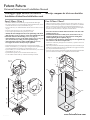
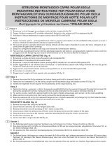
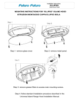
Futuro Futuro IS36POSITANO is a versatile island-mount range hood designed to bring a touch of modern elegance to your kitchen while effectively removing smoke and odors. With its sleek design and powerful performance, it's the perfect choice for those who demand both style and functionality. The hood features 4-speed settings, allowing you to adjust the suction power to your cooking needs. It also comes equipped with LED lights, providing ample illumination for your cooking surface. Installation is made easy with the included lattice-work and extension support elements.
Futuro Futuro IS36POSITANO is a versatile island-mount range hood designed to bring a touch of modern elegance to your kitchen while effectively removing smoke and odors. With its sleek design and powerful performance, it's the perfect choice for those who demand both style and functionality. The hood features 4-speed settings, allowing you to adjust the suction power to your cooking needs. It also comes equipped with LED lights, providing ample illumination for your cooking surface. Installation is made easy with the included lattice-work and extension support elements.


-
 1
1
-
 2
2


Futuro Futuro IS36POSITANO Universal Island Mount Installation Manual
- Type
- Universal Island Mount Installation Manual
- This manual is also suitable for
Futuro Futuro IS36POSITANO is a versatile island-mount range hood designed to bring a touch of modern elegance to your kitchen while effectively removing smoke and odors. With its sleek design and powerful performance, it's the perfect choice for those who demand both style and functionality. The hood features 4-speed settings, allowing you to adjust the suction power to your cooking needs. It also comes equipped with LED lights, providing ample illumination for your cooking surface. Installation is made easy with the included lattice-work and extension support elements.
Ask a question and I''ll find the answer in the document
Finding information in a document is now easier with AI
in other languages
- italiano: Futuro Futuro IS36POSITANO
- español: Futuro Futuro IS36POSITANO
Related papers
-
Futuro Futuro IS36EUROPE Installation guide
-
 Futuro Futuro IS36LOMBARDY-WHT Installation guide
-
 Futuro Futuro IS14JUPITER Jupiter Island Range Hood
-
Futuro Futuro IS34MURFORTUNA Owner's manual
-
 Futuro Futuro IS34MUR-MAYFLOWERLED User manual
-
 Futuro Futuro WL36JUPITERGLS Installation guide
-
 Futuro Futuro IS36JUPITERGLS Installation guide
-
 Futuro Futuro IS28ELLIPSO Installation guide


Other documents
-
Falmec MANHAT2222 Owner's manual
-
Falmec NY1281 Owner's manual
-
-
-
-
Falmec LUMEN ILOT 120 Owner's manual
-
-
Falmec Exploit Top Specification
-
HOMCOM 838-366V80ND User guide
-