Page is loading ...

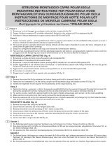
329
63.5
5mm
562
63.5
562329
Min 65mm
A
FIG.1
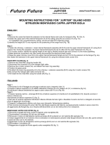
A
E
B
C
FIG.2
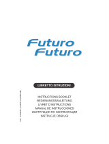
FIG.3
V1
V3
ISTRUZIONE MONTAGGIO CAPPA POLAR PARETE
V2
POLAR VERSIONASSEMBLY INSTRUCTIONS FOR WALL
V2
Fase 1
· Individuare l’altezza (A) desiderata tra cappa e piano cottura (Fig.1).
· Rimuovere il coperchio (C) agendo sulle relative viti di fissaggio (V1).
· Segnare i punti di foratura V2 e V4 seguendo le quote indicate in figura 1 e 2.
· Controllare con bolla di livello l’allineamento orizzontale dei 2 punti di foratura V2.
· Forare, inserire i tasselli ad espansione Ø8mm, ed avvitare le relative viti da
muro nella parete, lasciando circa 5mm tra sottotesta della vite e parete (fig.2).
· Fissare a muro la squadretta di sicurezza (E) nella posizione indicata in fig.1
Phase 1
· Identify the desired distance (A) between the hood and the hob (Fig.1).
· Remove the screws (V1) and remove the top (C)
· Mark the holes V2 and V4 following the dimensions of
the drawing (see fig. 1-2).
· Check with a spirit level that the 2 holes V2 are horizontal.
· Drill the holes and insert the expansion joints Ø8mm. Screw in the
wall fixing screws, leaving approx. 5mm between the underhead
and the wall (fig.2).
· Attach the security bracket (E) to the wall, as shown in fig.1.
Fase 2
· Centrare le asole della schiena della cappa sulle viti da muro.
· Agganciare la cappa e avvitare definitivamente le viti di fissaggio, solo dopo
aver verificato la loro tenuta.
· Nel caso di versione aspirante individuare la lunghezza ottimale
del tubo di scarico dei fumi ed eseguire il collegamento.
· Eseguire il collegamento elettrico solo dopo aver disinserito
l’alimentazione elettrica.
· Riposizionare il coperchio avvitando le relative viti (V1)
· Fissare la parte inferiore del distanziatore sulla squadretta (E) agendo sulle apposite
viti metriche (V3).
Phase 2
· Centre the holes on the back of the hood with the screws on the wall.
· Attach the hood to the wall and screw in the fixing screws. First check that they hold.
· If you are installing a suction hood install a suction tube of the correct length.
· Cut off power supply and then connect the hood's electrical system.
· Put the cover back in place and screw it in with the corresponding screws (V1)
· Attach the bottom section of the spacer onto the bracket (E) using the relevant
metric screws (V3).
Montaggio cappa con vetro
· Rimuovere il filtro metallico agendo sulla maniglietta (M).
· Disconnettere il connettore (S) del cavo dei faretti.
· Rimuovere il corpo(A) dal cono (B) svitando le 4 viti metriche M4 zigrinate (V4).
· Svitare leggermente le 2 viti metriche (VW) di centratura e di antirotazione
presenti nella flangia inferiore del cono (B) centrare le asole del vetro con le
viti metriche.
· Agganciare il corpo (A) al cono (B) con le 4 viti metriche M4 zigrinate.
· Riconnettere il connettore (S).
· Riagganciare il filtro metallico agendo sulla maniglietta (M) vedi fig.3.
Installation of hoods with a glass section
· Remove the metal filter using the corresponding handle (M).
· Disconnect the connector (S) of the spotlight cable.
· Remove the body (A) from the cone (B) by unscrewing the 4 knurled metric
screws M4 (V4).
· Unscrew a little bit the two centering and anti-rotation metric screws
(V5) in the bottom flange of the cone (B). Centre the holes on the glass
section with the metric screws.
· Attach the body (A) to the cone (B) with the 4 knurled metric screws M4.
· Connect the connector (S) again.
· Put the filter back in place using the corresponding handle (M) fig.3.
V4
/