Page is loading ...

Obtaining Other Language Versions: To obtain information in another language about the use of this product, please contact your local Crown Distributor. If you need
assistance locating your local distributor, please contact Crown at 574-294-8000.
This manual does not include all of the details of design, production, or variations of the equipment. Nor does it cover every possible situation which may arise during
installation, operation or maintenance.
The information provided in this manual was deemed accurate as of the publication date. However, updates to this information may have occurred. To obtain the latest
version of this manual, please visit the Crown website at www.crownaudio.com.
Trademark Notice: Com-Tech, BCA, Crown, Crown Audio, Amcron and Multi-Mode are registered trademarks of Crown International. DriveCore, DriveCore Install, IQwic,
PIP and PIP2 are trademarks of Crown International. Other trademarks are the property of their respective owners.
© 2014 by Harman International
®
, Inc. 1718 W. Mishawaka Rd., Elkhart, Indiana 46517-9439 U.S.A. Telephone: 574-294-8000
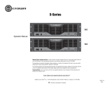
DCi Series – Network Display Models
Operation Manual
5038682 - 04/14
DCi 4|1250ND
DCi 8|600ND
Fault
Signal
Fault
Signal

DriveCore Install Network Display Series Power Amplifiers
Operation Manual
page 2
1. Read these instructions.
2. Keep these instructions.
3. Heed all warnings.
4. Follow all instructions.
5. Do not use this apparatus near water.
6. Clean only with a dry cloth.
7. Do not block any ventilation openings. Install in accordance with the
manufacturer’s instructions.
8. Do not install near any heat sources such as radiators, heat registers,
stoves, or other apparatus that produce heat.
9. Do not defeat the safety purpose of the Grounding-type plug. A
polarized plug has two blades with one wider than the other and
should not be used with this product. A grounding-type plug has two
blades and a third grounding prong and is the proper plug for this
product. The wide blade or the third prong is provided for your safety.
If the provided plug does not fit into your outlet, consult an electrician
for replacement of the obsolete outlet.
10. Protect the power cord from being walked on or pinched, particularly
at plugs, convenience receptacles, and the point where they exit from
the apparatus.
11. Only use attachments/accessories specified by the manufacturer.
13. Unplug this apparatus during lightning storms or when unused for
long periods of time.
14. Refer all servicing to qualified service personnel. Servicing is required
when the apparatus has been damaged in any way, such as power-
supply cord or plug is damaged, liquid has been spilled or objects
have fallen into the apparatus, the apparatus has been exposed to rain
or moisture, does not operate normally, or has been dropped.
15. Use the mains plug to disconnect the apparatus from the mains.
16. WARNING: TO REDUCE THE RISK OF FIRE OR ELECTRIC SHOCK, DO
NOT EXPOSE THIS APPARATUS TO RAIN OR MOISTURE.
17. DO NOT EXPOSE THIS EQUIPMENT TO DRIPPING OR SPLASHING
AND ENSURE THAT NO OBJECTS FILLED WITH LIQUIDS, SUCH AS
VASES, ARE PLACED ON THE EQUIPMENT.
18. THE MAINS PLUG OF THE POWER SUPPLY CORD SHALL REMAIN
READILY OPERABLE.
TO PREVENT ELECTRIC SHOCK DO NOT REMOVE TOP COVER. NO
USER SERVICEABLE PARTS INSIDE. REFER SERVICING TO QUALIFIED
SERVICE PERSONNEL.
TO COMPLETELY DISCONNECT THIS EQUIPMENT FROM THE
AC MAINS, DISCONNECT THE POWER SUPPLY CORD PLUG FROM THE
AC RECEPTACLE. THE MAINS PLUG OF THE POWER SUPPLY CORD
SHALL REMAIN READILY OPERABLE.
WATCH FOR THESE SYMBOLS:
The lightning bolt triangle is used to alert the user to the risk of electric
shock.
The exclamation point triangle is used to alert the user to important
operating or maintenance instructions.
IMPORTANT
DriveCore Install Series amplifiers require Class 2 output wiring.
MAGNETIC FIELD
CAUTION! Do not locate sensitive high-gain equipment such as
preamplifiers or tape decks directly above or below the unit. Because this
amplifier has a high power density, it has a strong magnetic field which can
induce hum into unshielded devices that are located nearby. The field is
strongest just above and below the unit.
If an equipment rack is used, we recommend locating the amplifier(s) in
the bottom of the rack and the preamplifier or other sensitive equipment at
the top.
Important Safety Instructions
FCC COMPLIANCE NOTICE
This device complies with part 15 of the FCC rules. Operation is subject
to the following two conditions: (1) This device may not cause harmful
interference, and (2) this device must accept any interference received,
including interference that may cause undesired operation.
CAUTION: Changes or modifications not expressly approved by the party
responsible for compliance could void the user’s authority to operate the
equipment.
NOTE: This equipment has been tested and found to comply with the
limits for a Class B digital device, pursuant to part 15 of the FCC Rules.
These limits are designed to provide reasonable protection against
harmful interference in a residential installation. This equipment gener-
ates, uses, and can radiate radio frequency energy and, if not installed
and used in accordance with the instruction manual, may cause harmful
interference to radio communications. However, there is no guarantee that
interference will not occur in a particular installation. If this equipment
does cause harmful interference to radio or television reception, which
can be determined by turning the equipment off and on, the user is
encouraged to try to correct the interference by one or more of the follow-
ing measures:
• Reorient or relocate the receiving antenna.
• Increase the separation between the equipment and receiver.
• Connect the equipment into an outlet on a circuit different from that to
which the receiver is connected.
• Consult the dealer or an experienced radio/TV technician for help.

DriveCore Install Network Display Series Power Amplifiers
page 3
Operation Manual
DECLARATION OF CONFORMITY
European Representative’s Name and Address:
David J. Budge
10 Harvest Close
Yateley, GU46 6YS
United Kingdom
Equipment Type: Commercial Audio Power Amplifiers
Family Name: DCi ND
Model Names: DCi 8600N, DCi 4|1250N
EMC Standards:
EN 55103-1:2009 EMC Compatibility – Product Family Standard for Audio, Video, Audio-Visual and Entertainment
Lighting Control Apparatus for Professional Use, Part 1: Emissions
EN 55103-1:2009 Magnetic Field Emissions-Annex A @ 10 cm and 20 cm
EN 61000-3-2:2006 Limits for Harmonic Current Emissions (equipment input current less than or equal to 16A
EN 61000-3-3:2008 Limitation of Voltage Fluctuations and Flicker in Low-Voltage Supply systems Rated Current less
than or equal to 16A
EN 55022:2010 Limits and Methods of Measurement of Radio Disturbance Characteristics of ITE: Radiated &
Conducted, Class B Limits
EN 55103-2:2009 EMC Compatibility – Product Family Standard for Audio, Video, Audio-Visual and Entertainment
Lighting Control Apparatus for Professional Use, Part 2: Immunity
EN 61000-4-2:2008 Ed 2.0 EMC Compatibility – Product Family Standard for Audio, Video, Audio-Visual and
Entertainment Lighting Control Apparatus for Professional Use, Part 2: Immunity
EN 61000-4-3:2010 Ed 3.2 Radiated, Radio-Frequency, Electromagnetic Immunity (Environment E2, criteria A)
EN 61000-4-4:2007 Radiated, Radio-Frequency, EMC Immunity (Environment E2, Criteria A)
EN 61000-4-5:2006 Surge Immunity (Criteria B)
EN 61000-4-6:2006 Immunity to Conducted Disturbances Induced by Radio-Frequency Fields (Criteria A)
EN 61000-4-11:2004 Voltage Dips, Short Interruptions and Voltage Variation
Safety Standard:
IEC 60065:2001 Ed 7 +A1:2005 +A2:2010 Safety Requirements – Audio, Video, and Similar Electronic Apparatus
CAN/CSA 60065-03 +A1 +A2 Safety Requirements – Audio, Video, and Similar Electronic Apparatus
UL Std No 60065-03 (2012) Safety Requirements – Audio, Video, and Similar Electronic Apparatus
I certify that the product identified above conforms to the requirements of the EMC Council Directive 2004/108/EC and the
Low Voltage Directive 2006/95/EC.
Issued By: Harman International.
1718 W. Mishawaka Rd.
Elkhart, IN 46517 U.S.A.
Signed _____________________________
Jeff Denman
Sr. Director of Manufacturing
Date of Issue: October 17, 2013
Due to line current harmonics, we recommend that you contact your supply authority before connection.

DriveCore Install Network Display Series Power Amplifiers
Operation Manual
page 4
Important Safety Instructions ............................................................................................................... 2
Declaration of Conformity ................................................................................................................... 3
Table of Contents .............................................................................................................................. 4
Welcome ...................................................................................................................................... 5
Installation .................................................................................................................................... 6
Front & Back Panel Features ................................................................................................................ 7
Hardware Setup and Configuration ........................................................................................................ 8
Precautions .................................................................................................................................... 9
Software Setup ................................................................................................................................ 10
Netsetter ....................................................................................................................................... 11
Offline/Online Operation ..................................................................................................................... 17
Software System Configuration ............................................................................................................. 19
General Purpose In/Out Control Port ....................................................................................................... 26
Aux Port/Sleep/Amp Status .................................................................................................................. 31
Advanced Operation .......................................................................................................................... 32
Signal Path ..................................................................................................................................... 41
Protection System ............................................................................................................................ 42
DCi Specifications ............................................................................................................................ 43
Service ......................................................................................................................................... 45
Warranty ....................................................................................................................................... 47
Crown Audio Factory Service Information ................................................................................................. 48
Product Registration .......................................................................................................................... 49
Table of Contents

DriveCore Install Network Display Series Power Amplifiers
page 5
Operation Manual
Thank you for purchasing a new Crown DriveCore Install Network™ Series installation amplifier, one in a complete line of high-performance amplifiers based on exclusive
DriveCore™ technology. DriveCore Install Network Series amplifiers are designed, engineered and manufactured to the industry’s highest quality standards, and provide
system integrators with the advanced features and flexibility required for challenging 21
st
century installed sound applications. Versatile, compact and highly energy-efficient,
DCiN Series amplifiers continue the unbroken Crown tradition of leadership in professional and commercial power amplifier technology.
Features
• Exclusive multi-patented DriveCore™ Technology – The patented DriveCore integrated circuit combines hundreds of
discrete circuits into one chip for better performance, lower power consumption and improved reliability.
• AVB Digital Audio Transport
• Configuration in HiQnet™ Audio Architect
• Programmable General Purpose Input/Output Control Port
• Digital Signal Processing
Input/Output EQ Filters
Crossover
Input/Output Delay
LevelMAX
TM
Limiters
• Priority Input Router
• PFC Power Supply – The universal PFC Power Supply offers reduced current draw and provides industry leading efficiency.
• Monitoring and Control over TCP/IP
• Real time Continuous Loading Monitoring
• Power Saving Modes – Power consumption in sleep mode is approximately 1W.
• Adjustable Auto Standby
• Remote Power Off – Sleep mode is activated via AUX port.
• 70 V / 100 V Direct Drive – Each channel is individually selectable for Low-Z or High-Z operation.
• Advanced Protection Circuits – Amplifier and loads are protected against shorted outputs, DC,mismatched
loads, overheating, over- or under-voltage, and high frequency overload.
• Complies with Green Edge by Harman – Environmentally friendly practices in design, manufacturing, and packaging complement energy-efficient operation.
How to Use This Manual
This manual provides you with the necessary basic information to safely and correctly set up and operate your amplifier. However, it does not cover every aspect of
installation, setup, or operation that might occur under every condition. For additional information, please consult Crown’s Amplifier Application Guide (available online at
www.crownaudio.com), Crown Technical Support, your system installer, or the retailer where this amplifier was purchased.
Welcome
Fault
Signal
Fault
Signal

DriveCore Install Network Display Series Power Amplifiers
Operation Manual
page 6
3.5 In.
8.9 cm
48.3 cm
19 In.
17 In.
43.2 cm
3
8
Fault
Signal
Unpacking
Unpack your amplifier and inspect for any damage that may have occurred during transit. If damage is found, notify the shipping company immediately. Only you can
initiate a claim for shipping damage, though Crown will be happy to help as needed. If the product arrived showing signs of damage, save the shipping carton for the
shipper’s inspection.
We also recommend that you save all packing materials for use if you ever need to transport the unit. Never ship the unit without the factory carton and packing materials.
Additional Materials
FOR INSTALLATION, YOU WILL NEED (not supplied):
• Input wiring cables
• Output wiring cables
• Flathead screwdriver
• Phillips screwdriver
• Rack for mounting amplifier (or a stable surface for stacking)
• Category 6 cabling
WARNING: Before you start to set up your amplifier, read and observe the Important
Safety Instructions found at the beginning of this manual.
Install the Amplifier
CAUTION: Before you begin, make sure your amplifier is disconnected from the
power source and that all the level controls are set to minimum output.
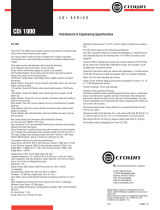
All DCi Network Display Series amplifiers are 3.5 in. (8.9 cm).high and 19 in. (48.3 cm)
wide and 17 in. (43.2cm) deep. (See Figure 1)
Mount the unit in a standard 19-inch (48.3 cm) equipment rack (EIA RS-310B). You can
also place a single amp on a solid, stable surface or stack multiple amps.
NOTE: Amplifiers should be supported at both the front and rear of the rack.
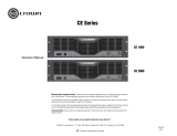
Ensure Proper Cooling
When using an equipment rack, mount units directly on top of each other. Close any open spaces in
the rack with blank panels. (Open spaces will reduce cooling efficiency.) DO NOT block front or rear
air vents.
The rack should be a minimum of two inches (5.1 cm) away from the amplifier, and the back of the
rack should be a minimum of four inches (10.2 cm) from the amplifier back panel.
Air flow is front to back as illustrated in Figure 2.
Installation
Figure 1
Figure 2

DriveCore Install Network Display Series Power Amplifiers
page 7
Operation Manual
Indicators:
Signal Indicators (green): LEDs indicate signal presence
Fault Indicator (red): Flashes when the amplifier output channel has stopped operating
Power Button
Power Ring Indicator (Green) - Illuminates
when the amplifier is plugged into a wall
outlet with acceptable power. NOTE: Power
Button is disabled when AUX port Sleep
circuit is used.
Note: Four channel model shown. Indications per channel pair are identical for 4 and 8 channel models.
Data Indicator (yellow)
Illuminates when data present on the data
network only. AVB connectivity
is not a part of this indicator.
Cooling Vent Grille
Filtered venting for cooling
circulation. Do not block or
cover these vents.
Front Panel Control
Allows user to edit and select
amplifier controls in the LCD
Screen.
Power Indicator (blue)
Illuminates when the amplifier is ON and
acceptable AC line voltage is present.
Blinks when AC line voltage is outside ±10%
range.
Flashes for 4 seconds if Power button pressed
when amplifier is in sleep mode.
LCD Screen
Shows enabled presets and
DSP functions in addition
to level clip and thermal
information.
Next-Prev-Menu/Exit
Buttons
Allows access to menu items
from the front panel.
Cooling Fan Outlet
Outlets for cooling air flow.
Do not block or cover these
outlets.
Auxiliary Connector
3-pin plug-in type connector,
Enables SLEEP mode and
monitoring of AMP STATUS unless
the amplifier is in any of these
conditions: OFF, SLEEP, or FAULT.
(see Page 31)
Output Connectors
One four-pole touch-proof
terminal strip per channel pair.
Accepts up to 10 AWG wire or
terminal forks.
AVB Digital Audio
Transport
AVB port for fault tolerance with control
through a second Ethernet port.
Secondary port not currently used.
Ethernet
For monitoring and control of the
amplifier over Category 5e wiring
through the Audio Architect
software.
GPIO
GPIO General Purpose
Input/Output port for
additional control and
monitoring of the amplifier.
Power Breaker
Resettable breaker to prevent
the amplifier from excessive
current draw.
Input Connectors
One 6-pin plug-in connector
per input pair. High impedance
balanced. (Refer to Page 8).
AC Power Inlet
Standard 20A IEC inlet
for detachable connector
Universal Power Supply
100 - 240V, 50/60Hz
Front Panel Features
Back Panel Features

DriveCore Install Network Display Series Power Amplifiers
Operation Manual
page 8
Wire Input Connectors
Crown recommends using pre-built or professionally wired balanced cables (two-conductor
plus shield). Balanced wiring provides better rejection of unwanted noise and hum; however,
unbalanced line may also be used. For more information, refer to the Crown Amplifier
Application Guide, available online at www.crownaudio.com.
Use 6-pin plug-in cable ends at the amp input connectors. A male connector is supplied for
each input of your model of amplifier. Additional connectors are available from Crown
(P/N 5024623).
Figure 3 shows connector pin assignments for balanced wiring and Figure 4 shows connector
pin assignments for unbalanced wiring. Note that for bridged operation, only the connectors for
odd-numbered channels (1,3,5,7) for each bridged pair need be wired.
AVB Connectors
For AVB audio connection, standard Category 6 cabling can be used.
When using the AVB Primary input connection, pass the CAT 6 cable twice through a Ferrite
core located as close to the amplifier as possible. This is to ensure compliance with emissions
regulations. See Figure 5 (Note: Secondary AVB port not currently used).
Hardware Setup and Conguration
Figure 3
Figure 4
Figure 6
CAUTION: Never connect the speaker return to the chassis of the amplifier, or damage to the amplifier may result.
CAUTION: Never use shielded cable for output wiring.
NOTE: Custom wiring should only be performed by qualified personnel. Class 2 output wiring is required.
Wire Output Connectors
Crown has designed an output cover that does not need to be removed to connect the output
wiring.
Crown recommends using the included spade connectors and two- or four-conductor, heavy
gauge speaker wire. You may use terminal forks up to 10 AWG or bare wire for your output
connectors. See Figure 6.
For best results, Crown recommends Panduit part #PV10-6LF-L or equivalent terminal fork..
For bare wire, it is highly recommended that output wiring is tinned. To reduce strain on input
and output wiring, Crown recommends the use of horizontal lacer bars. For best results,
Crown recommends Middle Atlantic part# LBP-4R90 or equivalent horizontal lacer bar.
For low-impedance loads, select the appropriate size of wire based on the distance from
amplifier to speaker.
Distance Wire Size
Up to 25 ft. (7.6m) 16 AWG
26-40 ft. (7.9-12.2m) 14 AWG
41-60 ft. (12.5-18.3m) 12 AWG
> 60 ft (18.3m) 10 AWG
Figure 5

DriveCore Install Network Display Series Power Amplifiers
page 9
Operation Manual
Startup Procedure
When first turning on your amplifier:
1. Turn down the level of your audio source.
2. Turn down the input attenuators of the amplifier.
3. Turn on the “Power” switch. The Power indicator should light.
4. Turn up the level of your audio source to an optimum level. Ensure that at no point in the signal chain is the signal being clipped in any way.
5. Turn up the level controls on the amplifier to the desired loudness or power level.
IMPORTANT: Before making any wiring or installation changes, turn off the amplifier and disconnect the power cord.
For help with determining your system’s optimum gain structure (signal levels) please refer to the Crown Amplifier Application Guide, available online at www.crownaudio.com.
Your amplifier is protected from internal and external faults, but you should still take the following precautions for optimum performance and safety:
1. Configure the amplifier for proper operation, including input and output wiring hookup. Improper wiring can result in serious operating difficulties. For
information on wiring and configuration, please consult Page 8 of this manual. For advanced setup techniques, consult Crown’s Amplifier Application Guide
available online at www.crownaudio.com.
2. Use care when making connections, selecting signal sources and controlling the output level. The load you save may be your own!
3. Do not short the ground lead of an output cable to the input signal ground. This may form a ground loop and cause oscillations.
4. Never connect the output to a power supply, battery or power main. Electrical shock may result.
5. Tampering with the circuitry or making unauthorized circuit changes may be hazardous and invalidate all agency listings.
6. Do not operate the amplifier clipping.
7. Do not overdrive the mixer, which will cause clipped signal to be sent to the amplifier. Such signals will be reproduced with extreme accuracy, and loudspeaker
damage may result.
8. Do not operate the amplifier with less than the rated load impedance. Due to the amplifier’s output protection, such a configuration may result in premature
clipping and speaker damage.
Remember: Crown is not liable for damage that results from overdriving other system components.
Precautions
Connect to AC Mains
Connect your amplifier to the AC mains power source (power outlet) using the supplied AC power cord set. First, connect the IEC end of the cord set to the IEC connector on
the amplifier; then, plug the other end of the cord set to the AC mains.
WARNING: The third prong of this connector (ground) is an important safety feature. Do not attempt to disable this ground connection by
using an adapter or other methods.
Make certain the AC mains voltage and current ratings are sufficient to deliver full power to all amplifiers. If the AC line voltage varies out of an acceptable range, the
amplifier’s power supply turns off and the blue Power LED flashes. The amplifier will turn back on when the AC line voltage returns to safe operating levels.
DCi Network Display Series amplifiers utilize a universal power supply. The AC voltage requirements are 100VAC - 240VAC, 50/60Hz (+/-10%). If the voltage exceeds these
requirements, then the Power LED will flash and the amplifier will stop passing audio until the voltage is within the requirements.

DriveCore Install Network Display Series Power Amplifiers
Operation Manual
page 10
Connect Loudspeakers and Configure for Loudspeaker Load
Determine load impedances and power requirements
Before making any connections, carefully check and review the total impedance for loudspeaker systems to be connected to each amplifier output. If multiple loudspeakers
are connected to one output (in series, parallel or series-parallel) for Low-Z operation, be certain the total system impedance is within allowed specification for the output.
When multiple loudspeakers are connected to one output for Hi-Z operation, be certain total tapped power is below the rated power output for the channel. For additional
information, please consult Crown’s Amplifier Application Guide (available online at www.crownaudio.com).
Note: Illustrations and some text references are for channel pair 1 - 2 only. Connections and settings are identical for channels 3 – 4 on
four-channel models and for channels 5 – 6 and 7 – 8 on eight-channel models. Each channel may be configured independently on multichannel
models.
Software Setup
Figure 7
Set Up and Configuration of the DriveCore™ Install Network amplifiers can be completed through HiQnet Audio Architect
TM
. The amplifier should be connected to a TCP\IP
network via the Ethernet connection on the back of the amplifier. Note: the AVB digital audio transport connectors cannot be used for control and monitoring of the amplifier.
To quickly configure your DriveCore™ Install Network amplifier, connect all of the amplifiers and configuration computer to the same network. For more information on
network configuration, please visit www.archimedia.harman.com. In the following example, we will only show amplifiers.
When Audio Architect™ is first loaded, the software will scan the network for HiQnet devices. All devices that are discovered on the network will be found under the ADD
DEVICE tab on the left hand tree menu. If the devices are not found, then the network may not be configured correctly. See Figure 7.

DriveCore Install Network Display Series Power Amplifiers
page 11
Operation Manual
NetSetter
Introduction
The Harman HiQnet NetSetter is a software tool which enables you to discover HiQnet devices and reconfigure network settings in real-time for each device. Its function is to
configure a system of devices to interoperate correctly on the same network and resolve conflicts quickly and easily.
NetSetter Window
The top of the NetSetter page list overall operational functions that are available. They are as follows:
• PC Adapter – A drop list menu that selects the Network Interface Card (NIC)’s adapter that NetSetter will use to attempt to discover HiQnet devices. All available
NIC’s are listed by IP Address. Selecting a new NIC will force a rescan of the network to which the new NIC is connected.
• Display – This menu filters the device in the grid view by:
- All Devices – Default setting. All discovered devices are displayed.
- HiQnet ID conflicts - Only discovered devices with HiQnet address conflicts are displayed.
- IP address conflicts - Only discovered devices with IP address conflicts are displayed.
- All conflicts - Only discovered devices with either HiQnet address conflicts or IP address conflicts are displayed.
- Locked - Only devices in a Locked configuration.
- Discovering-Only devices in the process of being discovered.
- Discovered - Discovered devices with no conflicts.
- DHCP / Auto IP - All devices which have been discovered with DHCP / Auto-IP enabled and those which have been set to use DHCP / Auto-IP on
applying the edits.
• Rescan Network – Clicking this button re-scans the network to which the currently selected NIC is connected.
• Export – The export button brings up a “Save As” window allowing you to save the HiQnet Addresses and IP Configurations of all devices on the network to a
.CSV (Comma Separated Values) format. This allows you to archive the information and open it in a spreadsheet program such as Microsoft Excel.
Figure 8

DriveCore Install Network Display Series Power Amplifiers
Operation Manual
page 12
At the bottom of the NetSetter window is an informational section that list the amount of discovered devices and the IP address of the DHCP Server. There is also information
regarding the PC HiQnet Address, IP Address, and Subnet Mask. There are four buttons that perform the following functions:
• Clear Container - Resets the Container / Position Venue data of the selected device. The action occurs on either Apply Current Edits or Apply and Exit
so that changes may be undone with the Undo Current Edits button.
• Undo Current Edits - Resets any open edits in the grid to the values as currently on the network.
• Apply Current Edits - Confirms any open edits in the grid. Devices update accordingly until connection is reestablished with HiQnet NetSetter.
• Apply and Exit - Confirms and saves any open edits in the grid. The devices update accordingly until connection is reestablished with HiQnet.
Exit HiQnet NetSetter - If you have made changes to NetSetter, and attempt to exit the program the following window will pop up.
Clicking "OK" will apply the edits you have made since opening NetSetter.
Clicking "Cancel" will return you to the program.
The NetSetter Grid
The grid is divided into 12 sections:
1. MAC Address 7. Random ID checkbox
2. DHCP / Auto-IP checkbox 8. Status
3. IP Address 9. Device Type
4. Subnet Mask 10. Device Name
5. Default Gateway 11. Container : Position
6. HiQnet ID 12. Locate
MAC Address
Displays the MAC Address(es) of the discovered device
If more than one MAC Address is discovered for a single device (HiQnet device MAC Address / AVB card MAC Address etc), the field is represented as a drop list. You may
select between the connected MAC Addresses. The data in this field cannot be edited.
• For a device connected to the same control network with two control MAC Addresses, the MAC Address field will be displayed in red.
DHCP / Auto-IP
If the discovered device is set to use DHCP / Auto-IP, the check box will be checked. If the discovered device is not using DHCP / Auto-IP, you may check the box so it will
do so on applying edits. The device row will then become selected. The device will attempt to have its IP settings configured by DHCP on applying the edits, if no DHCP
server is present the device will attempt to have IP settings configured by Auto-IP.
All devices in the current filter view may be set to DHCP / Auto-IP on by checking the check box in the column header. The individual check boxes for all devices will be
checked. If a single individual check boxes for all devices is subsequently unchecked the column header DHCP / Auto-IP checkbox will be automatically unchecked.
The devices in the current filter view may be set to DHCP / Auto-IP off by unchecking the check box in the column header.
DHCP server status will be among the information displayed at the bottom of the window. If a DHCP server is not detected, the information will read ‘DHCP server not
detected’. Checking a device’s DHCP / Auto-IP check box has no immediate effect on the column sort order.
Once edits have been made, it is critical to click the “Apply Current Edits” or “Apply and Exit” buttons.
Figure 9

DriveCore Install Network Display Series Power Amplifiers
page 13
Operation Manual
IP Address
Displays the IP address of the discovered device
A valid IP address may be edited inline. If the edited value scopes the device out of the current Display filter, it will not be visible.
Devices discovered with a conflicting IP Address
A discovered device with an IP Address that conflicts with one that has already been discovered will be displayed in red. A
conflicting IP Address may be edited inline if you wish to change the device IP Address on applying current edits.
If DHCP / Auto-IP is enabled the IP address field may not be edited inline.
Once edits have been made, it is critical to click the “Apply Current Edits” or “Apply and Exit” buttons.
Subnet Mask
Displays the Subnet Mask of the discovered device
The Subnet Mask may be edited inline.
• The device row will be ordered accordingly with the current column sort immediately on successful editing of the field.
• The device row will remain selected.
If DHCP / Auto-IP is enabled the Subnet Mask field may not be edited inline.
Once edits have been made, it is critical to click the “Apply Current Edits” or “Apply and Exit” buttons.
Default Gateway
Displays the Default Gateway of discovered device
May be edited inline.
• The device row will be ordered accordingly with the current column sort immediately on successful editing of the field
• The device row will remain selected
If DHCP / Auto-IP is enabled the Default Gateway field may not be edited inline
If the device is being rediscovered then:
• When the device is not selected, the device Default Gateway address field is displayed but is grayed out, represented in light gray.
• When the device is selected and highlighted in orange the field is represented in dark gray.
Once edits have been made, it is critical to click the “Apply Current Edits” or “Apply and Exit” buttons.
HiQnet ID
Displays the HiQnet address of the discovered device
May be edited inline if you want to change the device HiQnet address.
If the edited value scopes the device out of the current Display filter, it will not be visible. No devices will be selected.
If devices discovered with a conflicting HiQnet Address then:
• The HiQnet ID field of a discovered device with a HiQnet Address which conflicts with a HiQnet
Address which has already been discovered will be displayed in pink.
• A conflicting HiQnet Address may be edited inline if you want to change the device HiQnet Address.
• When the device is selected and highlighted in orange the field is represented in red.
• The HiQnet address is not displayed, instead a dash is displayed as grayed out.

DriveCore Install Network Display Series Power Amplifiers
Operation Manual
page 14
Devices not discoverable at the IP level
A device which is not discoverable at the IP level (invalid IP address etc) will not be able to report a HiQnet address. In this instance, the HiQnet ID field will display a ‘?’ to
indicate that the field may exist but that the software does not have enough discoverability of the device to determine the value.
A blank field or ‘-‘ implies the value is null. The HiQnet ID field may not be edited inline.
Once edits have been made, it is critical to click the “Apply Current Edits” or “Apply and Exit” buttons.
Random ID
The device will be given a random HiQnet address. If you want to set the HiQnet address of a device to a random ID, check the Random ID check box. If the check box is
unchecked before applying current edits, the prior HiQnet ID value will be restored.
All devices in the current filter view may be set to Random HiQnet ID by checking the check box in the column header. The individual check boxes for all devices will be
checked if a single individual check boxes for all devices is subsequently unchecked the column header Random ID checkbox will be automatically unchecked.
If all devices in the current filter view are set to Random ID on and the Random HiQnet ID column header check box is checked, all devices may be set to Random ID off by
unchecking the column header check box. The individual check boxes for all devices will be unchecked.
Devices not discoverable at the IP level
A device which is not discoverable at the IP level (invalid IP address etc) will not be able to report a HiQnet address. In this instance, the Random ID check box will be
unavailable.
Status
Displays the current discovery status of the device. The Status field may not be edited. Discovery status hierarchy is as follows:
• Discovered. If a device has a unique IP address and a unique HiQnet address, this condition will be shown unless the device is access controlled. When the
device is not selected, the ‘Discovered’ label is represented in green.
• IP conflict. If a device has an IP Address conflict, this error will be shown regardless of other status notifications. When the device is not selected, the ‘IP conflict’
label is represented in blue.
• HiQnet conflict. If a device has a unique IP address yet has a HiQnet address conflict, this error will be shown regardless of other status notifications. When the
device is not selected, the ‘HiQnet conflict’ label is represented in red.
• Locked. If a device has a unique IP address and a unique HiQnet address, this condition will be shown if the device is access controlled. When the device is not
selected, the ‘Locked’ label is represented in yellow.
• Discovering. This condition will be displayed if the device has had changes made to IP configuration or HiQnet address and HiQnet NetSetter is waiting
to reestablish connection. When a device being rediscovered is not selected, all fields within the device row are displayed but is grayed out,
represented in light gray.
Discovered - The ‘Discovered’ status is determined by the following conditions:
• The device is discoverable at the MAC Address level.
• The device has a valid and unique IP Address (manual or DHCP / Auto-IP).
• The device has a unique HiQnet address.
• The device is not Access Controlled.
IP conflict - The 'IP conflict’ status is determined by the following conditions:
• The device is discoverable at the MAC Address level.
• The device has an IP address which conflicts with another device which has already been discovered by NetSetter.
HiQnet conflict - The ‘HiQnet conflict’ status is determined by the following conditions:
• The device is discoverable at the MAC Address level.

DriveCore Install Network Display Series Power Amplifiers
page 15
Operation Manual
• The device has a valid and unique IP Address (manual or DHCP / Auto-IP).
• The device has a HiQnet address which conflicts with another device which has already been discovered by NetSetter.
Locked - The ‘Discovered’ status is determined by the following conditions:
• The device is discoverable at the MAC Address level.
• The device has a valid and unique IP Address (manual or DHCP / Auto-IP).
• The device has a unique HiQnet address.
• The device is Access Controlled.
When the device has been discovered in the Locked state, an Admin password dialog prompt will be displayed. The Admin password must be entered before any field can be
edited.
• A successful login with the Admin password is required to enable fields for subsequential editing.
• This state may need to be reset on rediscovery after applying current edits, requiring the Admin password to be entered again.
Discovering - The ‘Discovering’ status is determined by the following conditions:
• The device had been previously discovered at least the MAC Address level.
• Edits had been made to one or more fields.
• The device is being rediscovered after applying current edits.
Since the sort order automatically updates when a field within the sorted column is updated, the rediscovered device will occupy the same row on rediscovery. Unless DHCP
/ Auto-IP or Random ID has been set prior to applying current edits, in which case the rediscovered device will occupy the appropriate row in the current column sort order.
Device Type
The device class name is displayed, as reported by the discovered device. To the left of each device class name is displayed the brand icon. The software application name is
displayed for discovered PCs running an instance of HiQnet software:
• System Architect
• Performance Manager
• London Architect
The Device Type field may not be edited inline.
Devices not discoverable at the IP or HiQnet level
A device which is not discoverable at the IP level (invalid IP address etc.) or HiQnet address level (HiQnet address conflict etc) will not be able to report its class name. In
this instance, the Device Type field will display a ‘?’ to indicate that the field may exist but that the software does not have enough discoverability of the device to determine
the value.
A blank field or ‘-‘ implies the value is null.

DriveCore Install Network Display Series Power Amplifiers
Operation Manual
page 16
Device Name
The user-definable Device Name is displayed, as reported by the discovered device.
• May be edited inline if you want to change the Device Name.
• May not be edited for discovered PCs running an instance of HiQnet software.
Devices not discoverable at the IP or HiQnet level
A device which is not discoverable at the IP level (invalid IP address etc) or HiQnet address level (HiQnet address conflict etc) will not be able to report its Device Name.
In this instance, the Device Name field will display a ‘?’ to indicate that the field may exist, but that the software does not have enough discoverability of the device to
determine the value.
A blank field or ‘-‘ implies the value is null.
Once edits have been made, it is critical to click the “Apply Current Edits” or “Apply and Exit” buttons.
Container : Position
The Container and Position Venue Data is displayed (separated by a colon), as reported by the discovered device. The field is left blank for discovered PCs running an
instance of HiQnet software.
• System Architect
• Performance Manager
• London Architect
The Container / Position Venue Data may not be edited inline.
A selected device may have its Venue Data cleared (including all Building, Floor and Room Venue data) by pressing the Clear Container button. This action takes place on
applying current edits only and can be undone with the Undo Current Edits button.
Devices not discoverable at the IP or HiQnet level.
A device which is not discoverable at the IP level (invalid IP address etc) or HiQnet address level (HiQnet address conflict etc) will not be able to report its Device Name. In
this instance, the Device Name field will display a ‘?’ to indicate that the field may exist but that the software does not have enough discoverability of the device to determine
the value.
A blank field or ‘-‘ implies the value is null.
Locate
Clicking in the Locate column for a device will put the corresponding device on the network into a Locate state, and the Locate icon will be displayed.
• Clicking an active Locate icon will disable the Locate state for the device.
• Disabling the Locate state from the device will clear the icon.
• Devices may be put into Locate state independently from selection so that more than one device can be located at any one time.

DriveCore Install Network Display Series Power Amplifiers
page 17
Operation Manual
Offline/Online Operation
Audio Architect has two define modes of operation: Online and Offline. Offline operation allows the system to be configured without real time changes to the system. In this
mode, changes have to be sent to the edited device. In Online mode, changes to amplifiers are made real time.
When Audio Architect first opens, the Offline Design Tab is the ribbon presented, and the Device Toolbox appears on the left and an empty Properties window is at the
bottom. The Add Devices box is highlighted. When going Online, it may be necessary to Match Devices and/or Synchronize Venue.
Match Devices allows users to associate amplifiers within their venue design to amplifiers on the network. In the Match Devices tab, the following options are available:
• Refresh Networking: Clicking this button will temporarily take Audio Architect offline, then restart the network.
• Match
- Auto-Venue: Automatically enables matching between all the devices in the Audio Architect venue.
- Detach: Removes the device's virtual connection from Audio Architect.
• Editing
- Undo: Erases the last change done, reverting to the previous state.
- Redo: Re-establishes the previous state.
• Show – The checked items are displayed along side the appropriate devices in the venue; Device Names, Rack/Array Names, HiQnet Addresses, and IP
Addresses. In Synchronize Venue, each device will be shown with either a Receive icon or a Send icon.
• Receive – Device settings will be downloaded to the Audio Architect.
• Send – Device setting will be sent from Audio Architect to the device.
When going Online, the following options are possible:
1. If one or more devices in the Venue are not matched AND corresponding devices are available on the network, going online lands in Match Devices mode.
2. If all the devices in the Venue are matched, going online lands in Synchronize Venue mode. In Synchronize Venue mode, the user is given the option to either
Send data from Audio Architect to the device or Receive data from the device to Audio Architect.
3. If no devices require to be synced, going online lands in Run Venue mode.
Figure 10
Figure 11

DriveCore Install Network Display Series Power Amplifiers
Operation Manual
page 18
Each amplifier can be dragged into the room window. Each device will have a IP address listed on the left of the amplifier and a Name ID on the right on the amplifier. The
Name ID can be edited in the properties menu at the bottom of the page. The number to the left of Name ID is the HiQnet Device Address. The green circle only indicates that
the amplifier has been discovered on the network. The small box located below the rack allows quick access to amplifier factory panels. These panels include the following
items. Note: When a device is added to the window, it is automatically removed from the "Discovered".
• Factory Master Panels
• Monitor Panels
• Meter Panels
• Level and Mute Panels
Double clicking an amplifier will access the amplifier factor control panel. At this point, Audio Architect is in OFFLINE MODE. In OFFLINE MODE, amplifier changes are
not made in real time and will need to be sent to the amplifiers. Amplifier changes can also be sent in real time in ONLINE MODE. To go to ONLINE MODE, click on the GO
ONLINE tab in the Workflow bar menu. RECEIVE and SEND buttons will appear for each device, rack, and room in the design. This gives the user the option to just update a
single device, all devices in a rack or an entire venue. Click SEND to load the settings made in Audio Architect to the amplifier. Click RECEIVE to read the settings off of the
amplifier to be reflected in Audio Architect.
Figure 12
Figure 13

DriveCore Install Network Display Series Power Amplifiers
page 19
Operation Manual
Software System Conguration
Figure 14 (above) shows the DriveCore Install 2 channel configuration page. The 4 and 8 channel amplifier configuration pages have the same feature set.
The DriveCore Install Network amplifier includes Digital Signal Processing (DSP), multiple input/output routing options and a comprehensive diagnostics feature set.
All of these features can be adjusted in from the configuration page.
Amplifier Mode Settings
Hi-Z/Low-Z
The DriveCore Install Network amplifiers are capable of High-Z and Low-Z outputs. Each individual channel is capable of Hi-Z or Low-Z operation. To select Hi-Z or Low-Z
operation, double click on the mode button, the Amplifier Mode Setting Window will open (see Figure 15). Note: Choosing 70Vrms or 100Vrms is an amplifier global
setting, and affects all output channels selected for High-Z operation.
Figure 15
Global
Channel
Specific
The DCi Network Display Series amplifiers are very capable and flexible amplifiers. In the Amplifier Mode Setting window, the following items can be adjusted:
• Hi-Z/Low-Z on an individual channel basis
• 70Vrms or 100Vrms operation
• Any analog input can be sent to any amplifier output
• Mono Bridge Output - Output pairs can be bridged for mono operation

DriveCore Install Network Display Series Power Amplifiers
Operation Manual
page 20
Software System Conguration
Cascading Inputs
Cascading the analog inputs, or "Y-ing channels" gives more flexibility to the installation of this amplifier (See Figure 16). One input can be used to drive some or all of the
amplifier outputs. NOTE: By cascading the inputs, the corresponding input DSP functions for individual channels will be removed and only the output DSP functions will be
available (See Figure 17).
Figure 16 Use the "Y 1+2" etc. check boxes to cascade channel inputs.
Figure 17 With the "Y 1+2" box checked, both output Ch.1 and Ch.2 are fed by input Ch.1 and input processing is organized accordingly.
/