Page is loading ...

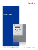
Manual
Precision meter VDEW
Kamstrup A/S
Industrivej 28, Stilling
DK-8660 Skanderborg
TEL: +45 89 93 10 00
FAX: +45 89 93 10 01
E-MAIL: [email protected]
WEB: www.kamstrup.com

2
5512-062 GB/06.2003/Rev. A1

Contents
3
5512-062 GB/06.2003/Rev. A1
1. Safety- and installation tips 5
2. Operating elements 7
3. LC-Display 9
4. EDIS (Energy-Data-Identification-System) 11
5. Operating the display 13
5.1.Choose display menu 13
5.2.Menu option call-up list 14
5.3.Menu option load profile list 14
5.4.Choose service menu 15
5.5.Menu option set mode 16
5.6.Menu option test mode 16
6. Wiring diagrams 17
7. Contact 19

4
5512-062 GB/06.2003/Rev. A1

1. Safety- and installation tips
5
5512-062 GB/06.2003/Rev. A1
The meters are to be used exclusively for
measuring electrical energy and must
only be operated within the specified
technical data.
When installing or changing the meter,
the conductor to which the meter is
connected must be de-energized. Contact
of parts under voltage is extremely
dangerous.
Therefore the relevant back-up fuse is to
be removed and stored so that other
people cannot insert this unnoticed.
Before opening the meter the secondary
circuit to the current transformer must
definately be short circuited. The high
voltage on the current transformer is
extremely dangerous and destroys the
current transformer.
The local standards, guide lines,
regulations and instructions are to be
obeyed. Only authorized personnel are
permitted to install the electricity meters.
Meters for direct connection are to be
fused against short circuits with a
back-up fuse of 63A or 100A and meters
with a transformer connection in the
voltage circuit with < 10A.

6
5512-062 GB/06.2003/Rev. A1

2. Operating elements
5512-062 GB/06.2003/Rev. A1
7
Parameter button
(under meter cover)
Impuls LED
Call-up sensor [A]
Optical data interface
(D0)
Reset button [R]
(sealable)
Call-up button [A]
Sealable trans-
former plate
LC-display
(VDEW-Standard)
Operation of the meter takes place via
the mechanical buttons:
Impuls-LED:
continuously lit-up = no energy
consumption or incorrect current flow
direction
The call-up sensor/button [A]
is used to activate the display mode and
to retrieve specific billing data and the
load profile.
The reset button [R]
is used for maximum resetting and also
for activating service functions. Since this
function is only for the energy supplier
this sensor is protected with a sliding
cover.
The seals may only be broken by
authorized personnel!

8
5512-062 GB/06.2003/Rev. A1

3. LC-Display
9
5512-062 GB/06.2003/Rev. A1
Operating display Communication display Display of phases Unit
Code area Value area Cusor field
The operating display represents the
current energy import as it was measured
from the meter (inductive/capacitive
reactive power).
The communication display appears
when there is communication with the
meter via data interfaces (optical,
electrical).
The display of the phases signalizes the
connection of the individual phase
voltages. With an incorrect rotating field
all of the three symbols flash.
In the code area the measuring values
are shown on the basis of the EDIS-code.
In the value area the measuring values
are represented with the corresponding
units.
In the cursor field the operating
conditions of the meters are represented.

10
5512-062 GB/06.2003/Rev. A1

4. EDIS (Energy-Data-Identification-System)
11
5512-062 GB/06.2003/Rev. A1
The Energy-Data-Identifications-System
EDIS is an identification system, which
was primary developed for electricity
purposes and is described in the DIN
43863-3. It serves to identify measured
values and data which through this are
clearly identifiable independent of the
device and producer. In the following list
common codes are described which are
often used with EMH electricity meters.
Measured variables
1. Active consumption + (import)
2. Active consumption - (export)
3. Reactive consumption + (import)
4. Reactive consumption - (export)
5. Reactive consumption Q I
..
8. Reactive consumption Q IV
Measured types
x. 2. Cumulative
(sum of the reset maxima)
x. 4. Runtime measured period + average
power of current measured period
x. 5. Average power of the last measured
period (load profile value)
x. 6. Maximum + Time stamp
(time, date, season)
x. 8. Energy
Tariffs
x. x. n. Tariff, n= 0 .. 4
Pre-values
x. x. x. n. Pre-values, n= 0 .. 99
(referring to the reset counter/register)

12
5512-062 GB/06.2003/Rev. A1

5. Operating the display
5.1. Choose display menu
13
5512-062 GB/06.2003/Rev. A1
For operating the display the following is
valid:
Call-up button [A]:
Pressing < 2s: Switch over to the
next value in the
list or menu option
Pressing > 2s
and < 5s:
Activating the
displayed menu
option or skipping
of pre-values
Pressing > 5s: Return to the
operating mode
(scrolling dislpay)
from every
condition of the
display
Reset button [R]:
Except in the set- and display test mode
pressing > 2s and < 5s always initiates a
reset. An arbitrary long pressing in the set
mode always initiates a transfer of the
edited digit or value.
The EDIS-codes represented in the
following illustrations and also the
information in the value area are
examples.
5.1.1. Operation display (scrolling)
5.1.2. Display test mode
[A] - button short
[A] - button short
[R] - button short (cont. the service menu)
5.1.3. Menu option: Call-up list
5.1.4. Menu option: Load profile
5.1.5. Menu option: End
[A] - button short
[A] - button long (cont. in the call-up list)
[A] - button short
[A] - button long (cont. in the load profile list)
[A] - button short

5.2. Menu option call-up list
5.3. Menu option load profile list
14
5512-062 GB/06.2003/Rev. A1
Tip: Operation of the [R] - button in the
call-up list and the load profile list
activates a reset.
5.2.1. Menu option: Call-up list
5.2.2. First register
5.2.3. Next register
[A] - button long
[A] - button short
[A] - button short
5.2.4. Pre-value
5.2.5 Repeat position3+4forall
desired values
[A] - button long for the next register
[A] - button short for registers and pre-values
5.2.6. End of the call-up list
[A] - button short
5.3.1. Menu option: Load profile list
5.3.2. Last date
[A] - button long (to the operat. display)
[A] - button short (cont. in position. 2)
[A] - button long
[A] - button short
5.3.3. Date of the previous day
5.3.4. Time of the first entry
[A] - button long
[A] - button short

5.4. Choose service menu
15
5512-062 GB/06.2003/Rev. A1
5.3.5. Next value
[A] - button short [A] - button short (cont. in position 4)
[A] - button long
5.3.6. End of the load profile list
5.4.1. Operating display
5.4.2. Display test mode
5.4.3. Menu option: Set mode
[A] - button short
[A] - button long (cont. in the set mode)
5.4.4. Menu option: Test mode
5.4.5. Menu option: End
[A] - button short
[A] - button long (cont. in the test mode)
[A] - button short
[R] - button short
[A] - button

5.5. Menu option set mode
5.6. Menu option test mode
16
5512-062 GB/06.2003/Rev. A1
5.5.1. Menu option: Set mode
5.5.2. First set value
5.5.3. Next value
5.5.4. First digit flashes
[A] - button long
[A] - button short
[A] - button short
[A] - button short
5.5.5. Increase digit by 1
5.5.6. Repeat positions4+5for
further digits
5.5.7. All digit flash
5.5.8. End of the set mode
[A] - button short (maintain old data)
[R] - button long (save new value)
[A] - button short (cont. in position 2)
[A] - button long (to the operat. display)
[A] - button short
Tip: In the test mode the energy registers
are displayed with a higher digitness.
5.6.1. Menu option: Test mode
5.6.2. First value
[A] - button long
5.6.3. Next values
5.6.4. Repeat postition 3 for desired
values
Repeat postition 3 for desired values
[A] - button short
[A] - button short

17
6. Wiring diagrams
5512-062 GB/06.2003/Rev. A1
You will find the valid wiring diagram on
the inside of the terminal cover and also
on the delivery documents.

18
5512-062 GB/06.2003/Rev. A1

19
7. Contact
5512-062 GB/06.2003/Rev. A1
Kamstrup A/S
Industrivej 28, Stilling
8660 Skanderborg
TEL.: +45 89 93 10 00
FAX: +45 89 93 10 01
E-MAIL: [email protected]
WEB: www.kamstrup.com

20
5512-062 GB/06.2003/Rev. A1
/